Overview
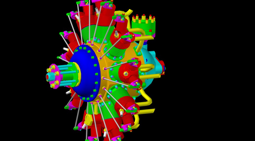
Lee Hodgson’s late father, Sam, created this wonderful scale engine beginning way back in 1936. Lee has reworked the plans, and now offers a thick tome of CAD drawings and all the necessary information to re-create one of these masterpieces available at AgelessEngines.com. With thousands of construction hours, it is truly a masterpiece of both skill and perseverance.
The plans for the Hodgson radial are produced by CAD and are very well done. The are some minor mistakes throughout and I’ll try to point those out as I progress through the construction on these many pages.
When starting any machining project, and most certainly one of this magnitude, I like to construct a complete 3D CAD solid model. Most of the time, the sequence of creating a CAD solid is very much like machining. You start with a rectangular block, and subtract cylinders to make holes, fillet and chamfer edges, and subtract other rectangular regions to make slots and cut-outs. I find that thinking how to draw these different CAD parts gets me 90% of the way to knowing how to fixture, hold, and the sequence of machining operations needed to make the actual parts. It’s also an excellent check on all of the dimensions as well as a great tool for understanding how all the parts fit together, and what dimensions are critical and which ones are not.
I spent over 100 hours just creating the solid model of this engine in AutoCAD, and many more making small changes and “improvements!”. I’d love to be able to share this model with everyone, but the Hodgson’s have put a lot of work into creating this wonderful engine so, you’ll just have to buy the plans from them and create your own. As I pointed out earlier, building the CAD model is a great learning experience, so you’d probably want to do it yourself anyway. While I’m unable to share my complete model, I will be posting CAD models of special tools and modifications I’ve made.
Construction Logs
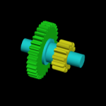
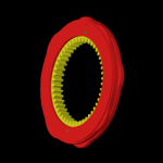
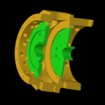
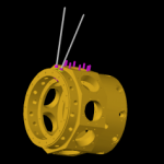
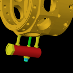
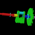
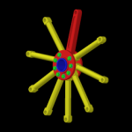
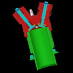
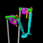
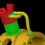
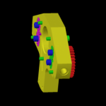
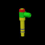
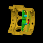
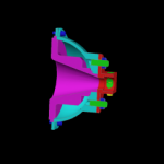
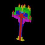
I’ve broken down the parts into function related groups. In each group, I’ll be creating pages for the individual parts documenting the fabrication of each part starting with the CAD model. On the left in each group is an image of the CAD model for that part group. Moving your mouse over the individual part links to the right of the image will highlight that part in the model. If the part has a construction log, you can click on the part number link to go to the log.
Guide to the construction logs below:
Finished parts have no decoration
• Denotes work in progress
~ Denotes pages coming soon
The Front Crankcase Cover
The Crankshaft Assembly
~032 Front crank
~034 Bearing sleeve
035 Crank cheeks
~036 Main journal
~037 Rear crank
~039 Gear H-3230
~041 Gear G-481Y-P
•043 Impeller
The Pistons & Rings
050 Pistons
051/052 Wrist pins & buttons
~053 (old 47) Compression ring
~054 (old 48) Oil control ring
The Cylinder & Heads
055 Head
056 Valve seat
057 Head gasket
058 Valves, ~Lapping the Valves
059 Valve spring cup
061 Valve spring retainer
•064 Cylinder
The Intake & Exhaust Pipes
~070 Intake pipe
~071/072 Exhaust pipe
073 (old 68) Mounting plate
074 (old 69) Crankcase mount
075 (old 70) Gasket
The Oil Pump Assembly
•077 Housing
•079 Gear, driven G-174
•082 Gear, pressure G-163
•083 Gear, scavenge G-165
The Electronic Ignition
~099 Distributor cap
~100 Spark plug terminals
~101 Coil terminal
~102 Rotor contact
~103 Insulator
~104 Lubricating felt
~106 Distributor housing
~107 Bushing
~108 Rotor
~109 HED III electronic ignition
~110 Distributor shaft
~112 Gear G-481YG
The Oil & Fuel Tank
The Mounting Stand
Disclaimer and License
All material, including the CAD drawings, relating to the construction of the Hodgson Radial presented on this site is free to use any way you see fit. However, no guarantees are made regarding the accuracy or correctness of the material presented here.

