- Hodgson Part 035, Crank Cheeks
- Hodgson Part 043, Impeller
- Understanding Crankshaft Counterweights
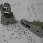 This is a long page not because the part was especially difficult, but because of a major problem part way through that caused me to have to re-make the part. I decided it was important to let others know about the problem I encountered so I’ve included that in this documentation.
I also deviated from the process sheet provided in the plans. Here is an 035 Crank Cheek Setup sketch of the part layout I worked from. My part includes a few extra 3/16″ dowel pin holes that will be used to index the part in the mill so I don’t have to do any critical angle setups on an odd shaped part.
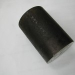 I had some 50mm heat treated 416 stainless round left over from another job. It had been heat treated to HRc 32-35 so it was still easy to machine but I thought the extra strength would help insure the square drive holes did not wallow out, and the extra hardness would make for a nice surface finish.
I started off by sawing off a piece about 2-7/8″ long. I needed the extra length because I change the processing plan to make this a little easier to produce and the extra length would be needed for a couple of tooling holes.
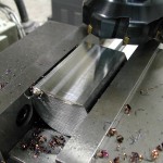 Since I needed flat stock and the raw material was round, the first order of business was to square up the material.
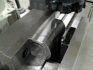 Here I’m using a ball bearing to make sure the previously machined face is tight against the fixed vise jaw.
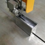 With the material squared up and the length and width left oversize, the next step was to split the stock into two pieces. These pieces were then machined to the finished 0.500″ thickness.
With the pieces tightly clamped together, a small weld was run along each end to join the parts back together.
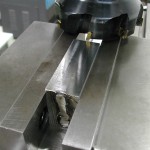 The long edges of the rejoined pieces were then skimmed to finish the block to the 1.63″ stock width. This insured that long edges of the welded parts would be square to the faces and that there would be no mismatch between the two final crank cheeks.
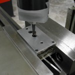 Next the four 0.1885″ holes for the tooling pins were placed in the part. The rod journal hole was drilled undersize, and the 0.390″ pilot hole for the 3/8″ square broach was drilled and bored to size.
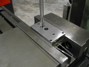 Finally, the rod journal hole was reamed to 0.375″.
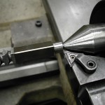 The 3/8″ broach was modified by turning a small round section on the end so that the broach could be chucked in a collet and started into the part on the mill to enhance alignment.
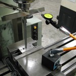 The quill was centered over the pilot hole and the broach mounted in a collet, and aligned square with the table. The indicator in the image was to verify that the broach did not rotate while being started. The quill was then used to start the broach into the hole.
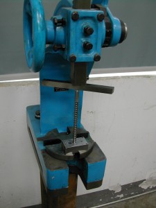 After starting the broach in the mill to insure it was both normal to the crank cheek surface, and aligned square with the part, it was moved to the arbor press to finish the job. This is where things went south.
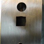 While the broach cut a nice on-size square hole aligned with the part, it slid off center as it went through. You can see in this photo the remnants of the 0.390″ pilot bore on the north and east sides of the hole, while they are completely gone from the south and west sides. All in all, the broached hole slid 0.020″ off-center.
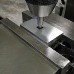 I was short on material and I wasn’t sure what I could do different to insure the square hole came out correct the second time. So, after I went through the above steps to prepare a second welded stack of material from my round stock, I had a friend EDM the square hole in the match-pair blank for me.
In case the EDM’ed hole was not perfectly centered in the blank, all subsequent operations were performed relative to the square hole’s center.
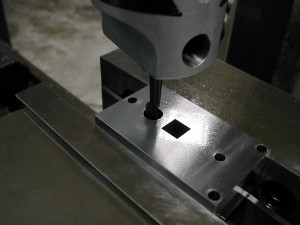 Again, the four 0.1885″ tooling holes were drilled and reamed, and the journal hole was drilled, bored, an reamed to size.
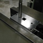 Here is the final reaming operation on the journal hole.
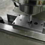 Now it’s time to thin the crank cheeks down to the 0.250″ thickness in the upper portion away from the balance weights. Here, I’ve inserted a dowel pin in the alignment hole and this is touching against a stop clamped on the bottom of the mill vise. The square hole is then indicated with the part against the stop.
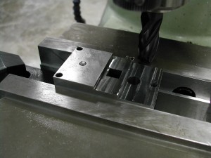 The first side is now milled down to the 0.250″ (0.750″ over-all) finish thickness at this point. The part is flipped, and re-indexed against the pin again and the second side milled to 0.500″ over-all thickness.
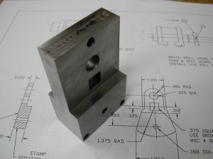 At this point, we still have our two crank cheeks securely welded together insuring that each is a mirror image of the other.
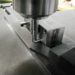 With dowel pins inserted into the alignment hole and the end tooling hole the part is clamped in the vise with the pins resting on the top of the vise jaws. A stop is clamped such that the pin in the alignment hole touches this stop so we can indicate the part and index it to narrow both sides in one setup.
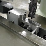 The edges of the cheeks are now milled down to the finished 0.812″ dimension.
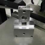 By milling from both sides in this setup until the 0.812″ dimension is reached we insure that the part maintains symmetry, and that the drive and journal holes are in the exact center of the part.
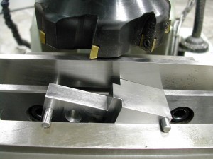 The tooling holes make it easy to machine the angles on the sides of the crank cheeks. The angle finishes approximately 0.052″ above the plane of the tooling pins, so here I am setting my tool height with a parallel. It’s now just a matter of milling the cheek angle down to the finish height, flipping the part to the other side and repeating the process.
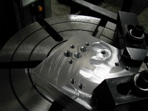 By putting in three easy to place X-Y coordinate holes in the original blanks, we’ve made it relative easy to process this part without complex setups and measurements.
The two end radii will be milled using the rotary table and a sacrificial tooling plate. I’ve already indicated in the center of my rotary table, and clamped my well-used plate to the surface. With the index set to 0.0°, I’ve tapped two 3/8″-24 holes – one on center and one offset 0.5625″ in X.
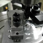 Here I’ve mounted the crank cheeks to the rotary table with two small scraps of aluminum to act as spacers so the cheeks can be firmly clamped to the tooling plate with two SHCSs. Since I chose to mill the large radius first, the bolt through the square hole goes into the hole tapped on the rotary table’s center.
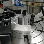 The large radius is now milled. Milling this radius also removes the weld joining our two parts from this end.
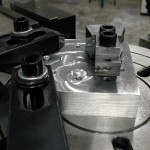 The part is now unbolted and the round hole is bolted down to the central tapped hole.
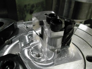 The 0.406″ radius is now milled on the small end removing the weld and separating our two crank cheeks.
 Two finished crank cheeks ready for assembly onto the crankshaft.
Disclaimer and License
All material, including the CAD drawings, relating to the construction of the Hodgson Radial presented on this site is free to use any way you see fit. However, no guarantees are made regarding the accuracy or correctness of the material presented here.
Links Used On This Page
(CAD drawings are in AutoCAD 2010 Format)

