
- Hodgson Part 091, Rear Cover Casting
- Hodgson Part 092, Air Guide
- Hodgson Part 095/096, Carburetor Mount & Lock Cylinder
 The air guide was made from a 125mm diameter by 300mm piece of Aluminum 7075-T6. I bought a stick of this long enough to make the front cover, crankcase, rear seal plate, air guide, impeller, and a few fixtures. The diameter was needed to accommodate the crankcase so I did end up wasting a little material on the other parts.
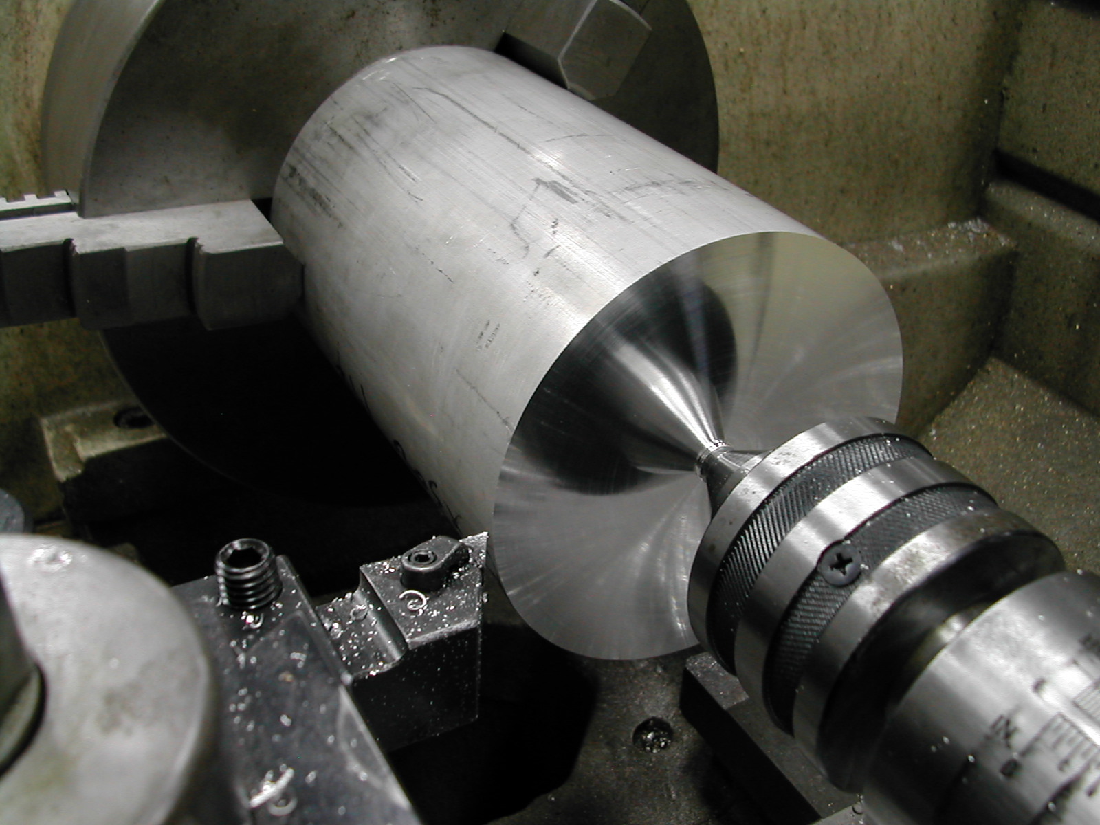 Since this was the next part to come off my piece of stock after the 4.75″ for the crankcase, the stock extended from the chuck a significant distance so I ran it with a live center.
With the center in place the first step was to make a facing cut to set the carriage zero point.
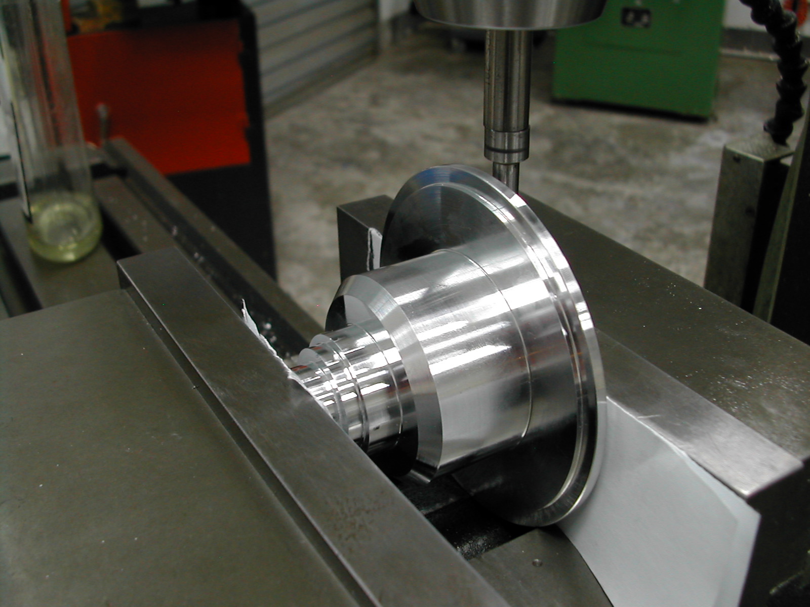
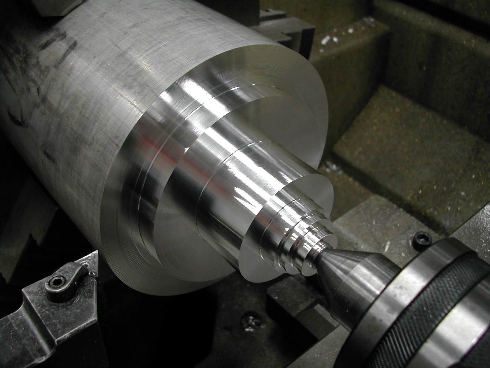 I rough turned the air guide leaving 0.025″ on the faces and 0.050″ on the diameters. These were all 0.25″ DOC passes with a heavy feed rate so I let the part cool before making my finishing cuts.
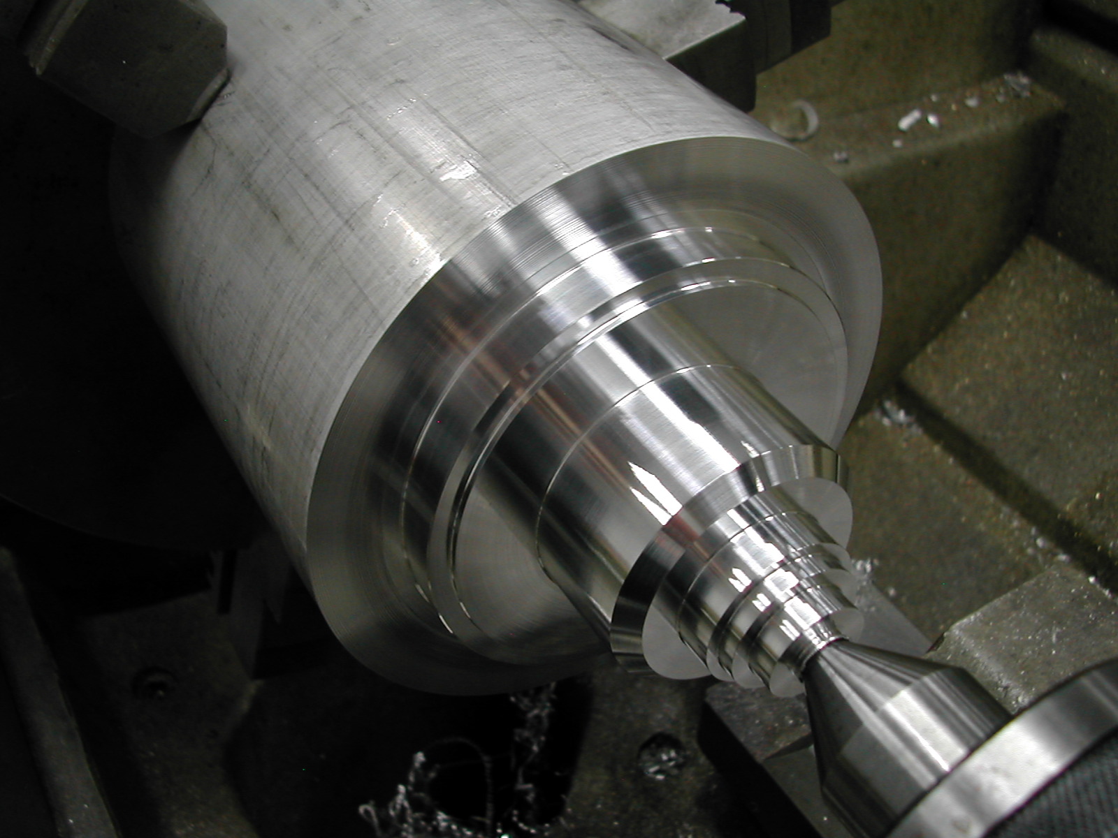 All diameters and step lengths are now to print. I’ve added a 45° chamfer on the 2″ diameter just for looks.
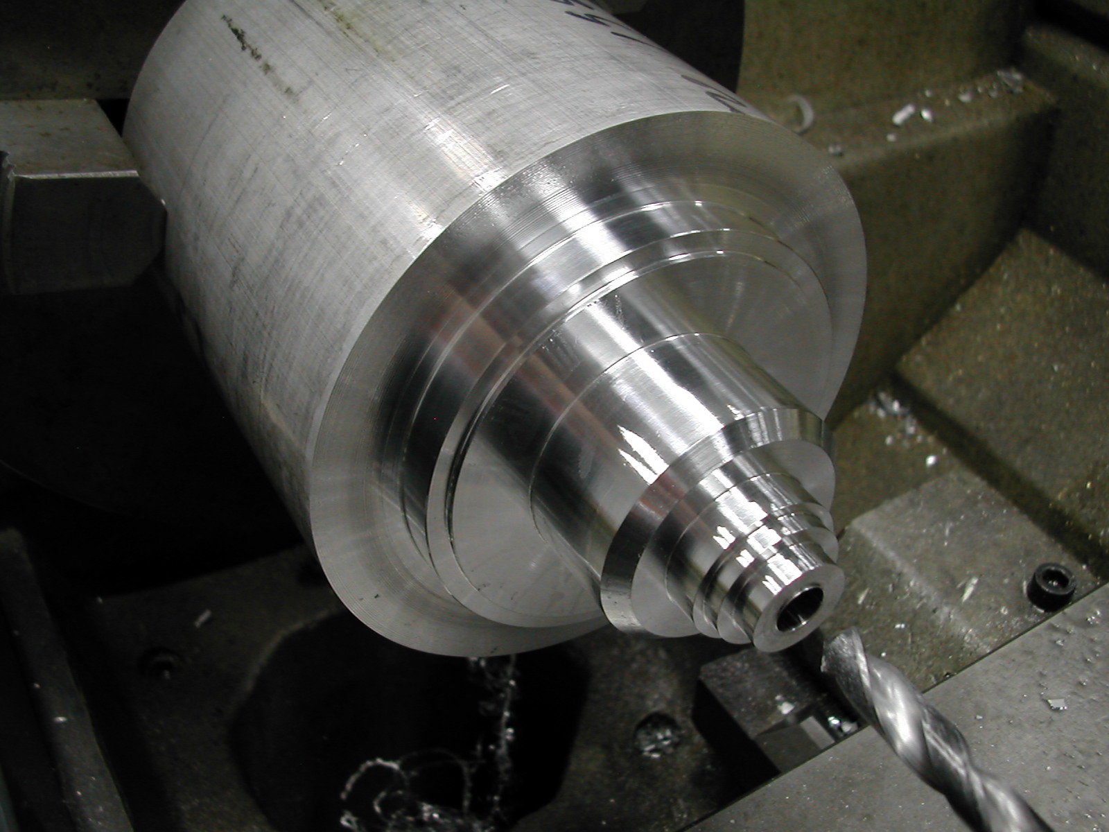 Since I already had a center in this end, I went ahead and ran a 7/16″ drill through the length of the part.
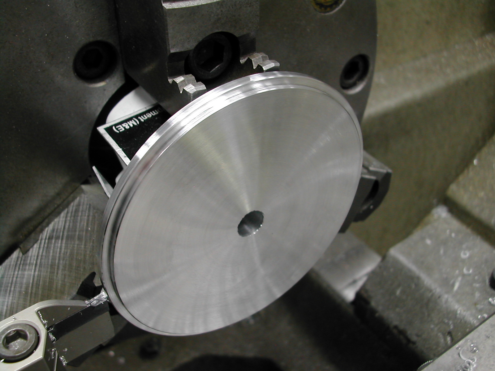
 After a trip to the bandsaw to remove the blank from the stock, I reversed the part in the chuck and clamped on the 2.000″ diameter and indicated the part in.
I have a nice Buck Adjust-Tru 3-jaw chuck. If I didn’t have this, I would have needed to use an independent 4-jaw chuck to center the part.
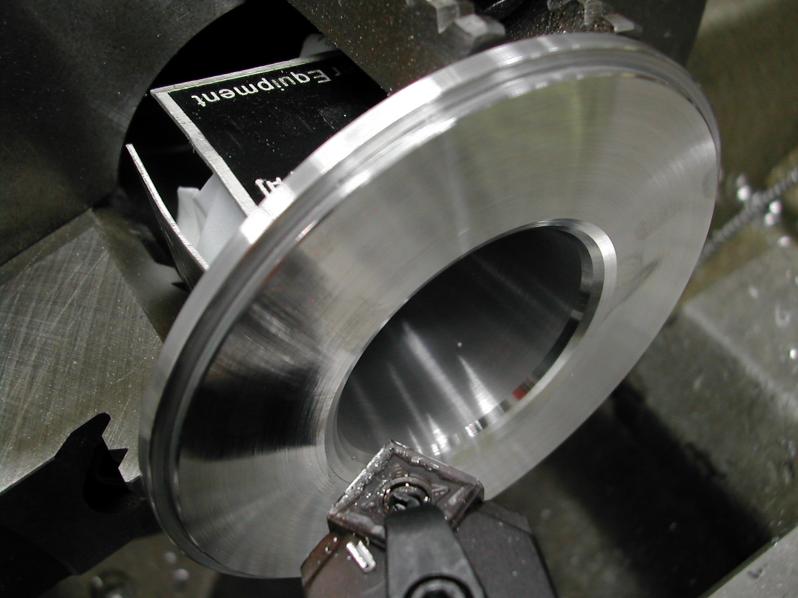
With the part running true, the flange was faced to the finished thickness.
 The locating lip was added. This should be fit to the crankcase and be sure to add the necessary chamfers to clear any radii in the steps in the crankcase.
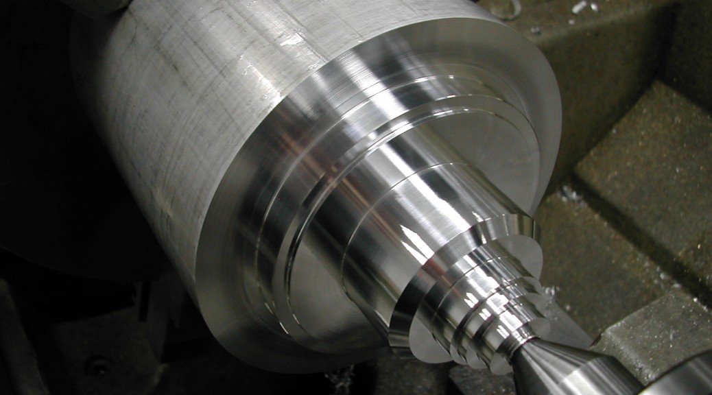
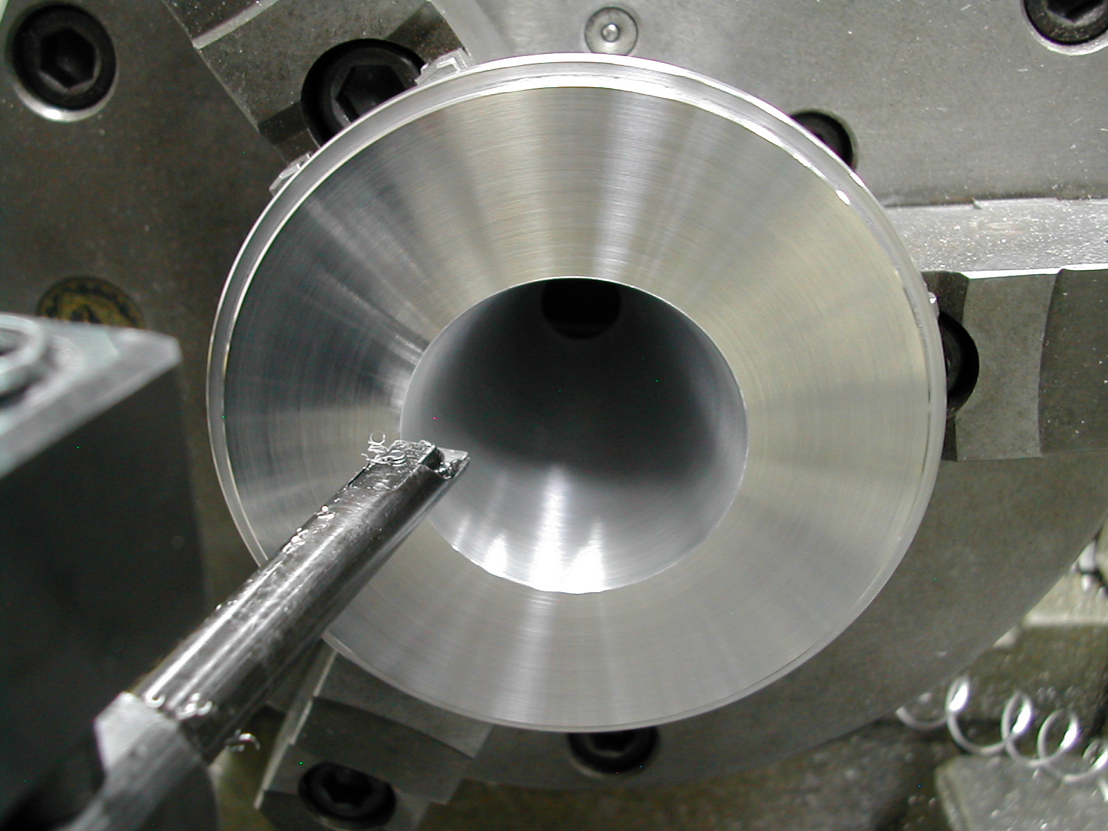 My CAD model gave a slightly different angle for the cone than the plans. I opened the center up at a 16.1° angle per side to a large diameter of 1.634″.
This results in a little end just smaller than my OS 60KC carburetor. I’ll open this and the carb mount up with a reamer to 0.500″ when both are finished.
 I’ve approximated the 0.25″ radius with three facets.
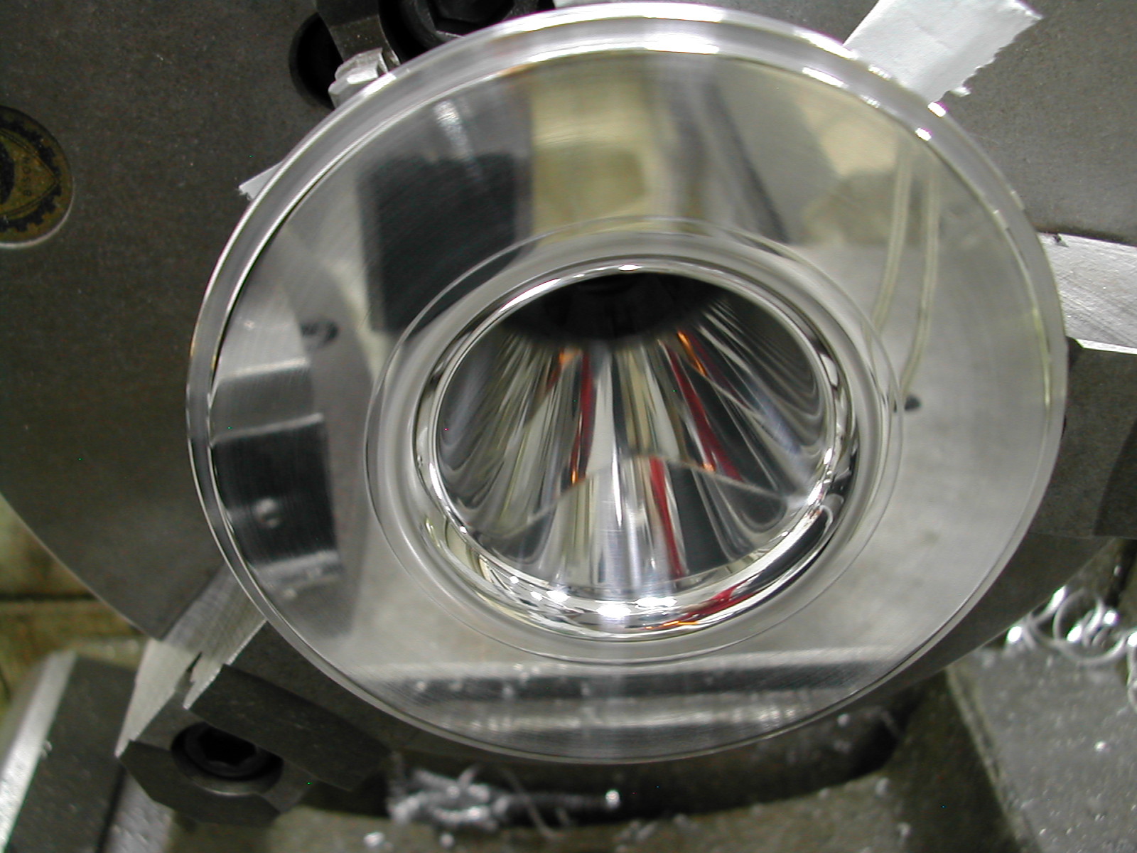 A scraper and some progressive sanding from 320 grit up to 3000 grit followed by a quick polish with some 3µ paste on a tissue finished out the air guide turning operations.
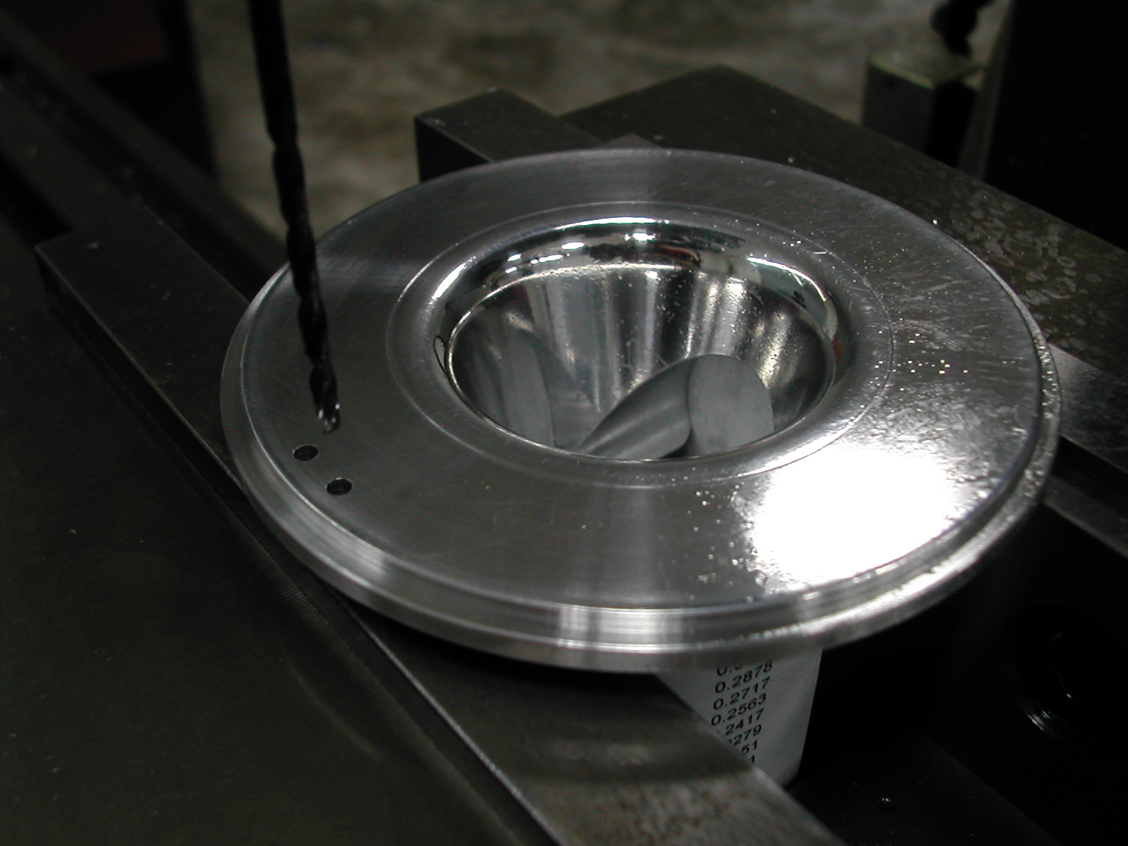
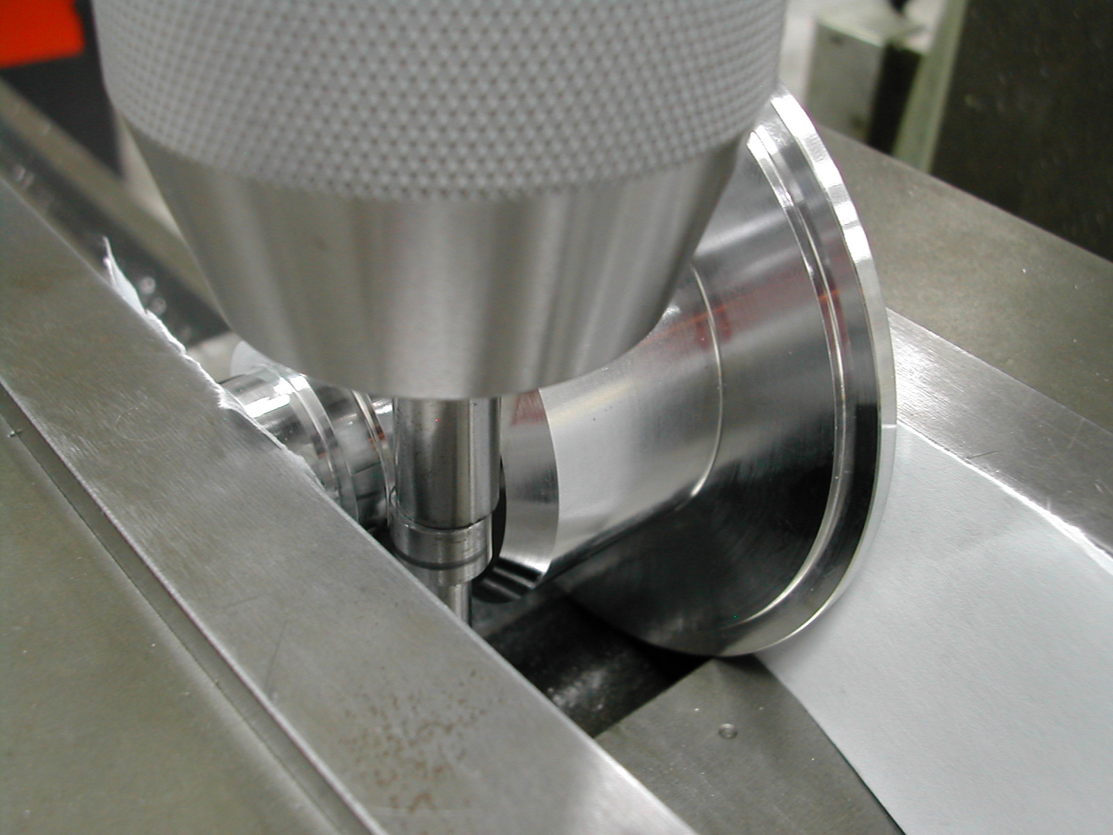 With the air guide clamped in the mill vise, I’m locating the center.
 Next step is to move down the 1.040″ amount for the 1.030″ diameter distributor gear clearance cut.
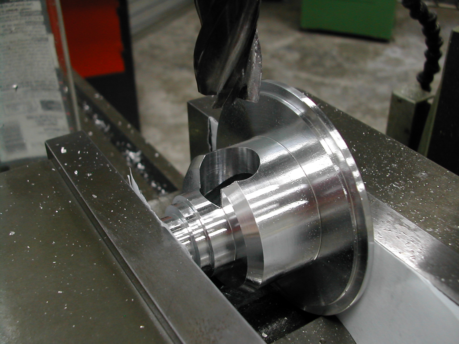 I’ve started the clearance bore with a 1/2″ drill and I’m following that with a 20mm end mill (the largest I have).
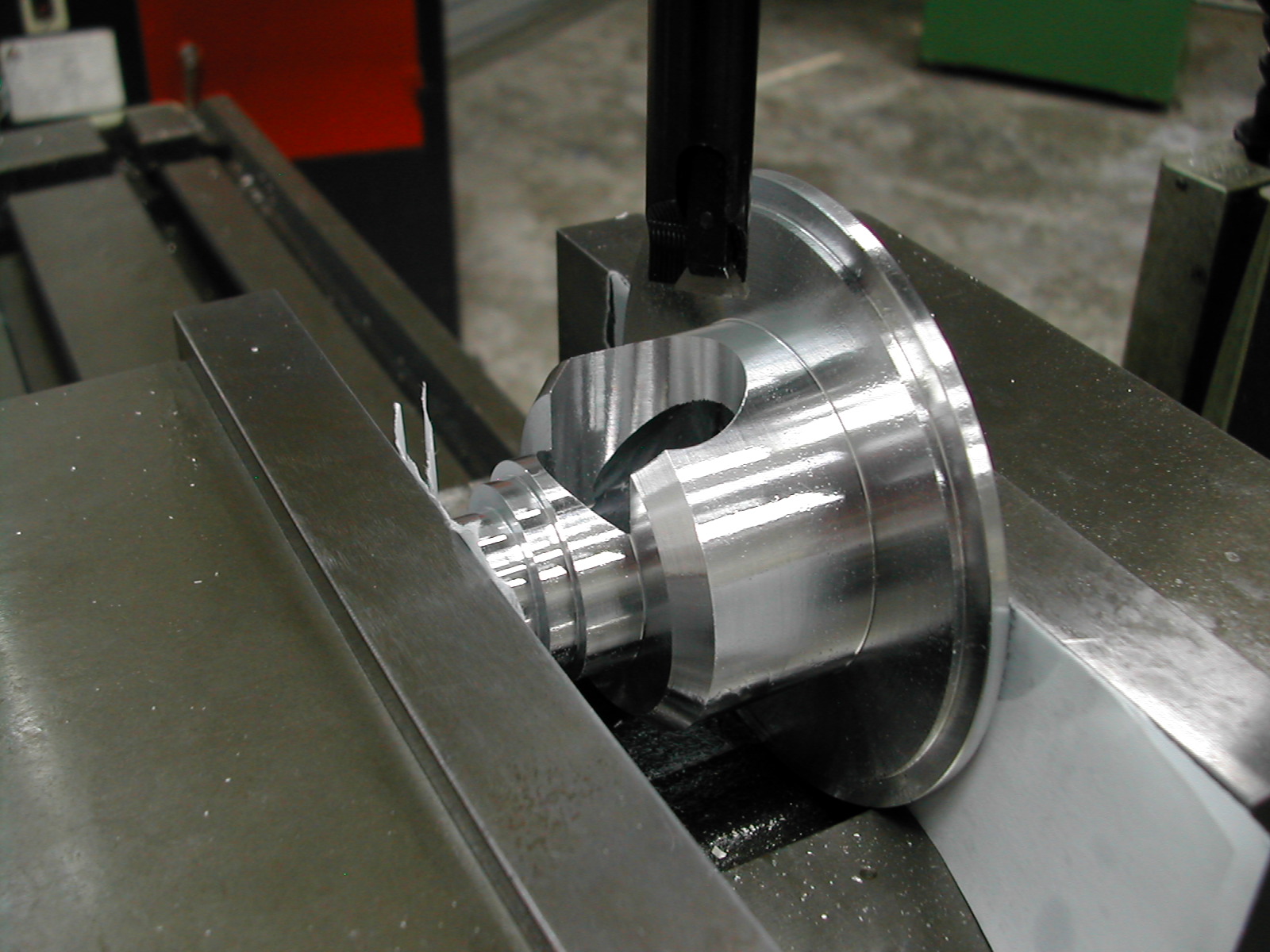 The boring head is then used to open the hole up to 1.030″ diameter.
 This cut is not on the plans, but I’ve milled a flat here so I can clamp this against the vise face to locate the two drain holes in the proper relation to the bore.
With the flat clamped against the jaw, it’s now a simple matter of locating the center of the air guide and stepping off opposite the flat to locate the two drain holes.
This completes the machining operations on the air guide.
Disclaimer and License
All material, including the CAD drawings, relating to the construction of the Hodgson Radial presented on this site is free to use any way you see fit. However, no guarantees are made regarding the accuracy or correctness of the material presented here.
Links Used On This Page