
- Hodgson Part 091, Rear Cover Casting
- Hodgson Part 092, Air Guide
- Hodgson Part 095/096, Carburetor Mount & Lock Cylinder
 Before starting on the rear cover, you should complete the air guide since you may have to make some cuts in the casting that are not on the plans to get the air guide to fit. If you are making your own carb mount, you’ll want to review that page and finish most of the work on that as well to save yourself a little time later.
Also, if you have access to a shot peen machine or sandblaster, you may want to remove the two unneeded bosses on the cover. If you do that before any machining operations, you should be able to blast it and completely remove any traces of the bosses. I opted to leave mine on since I didn’t have a good way to remove the filing and grinding marks that would have been left.
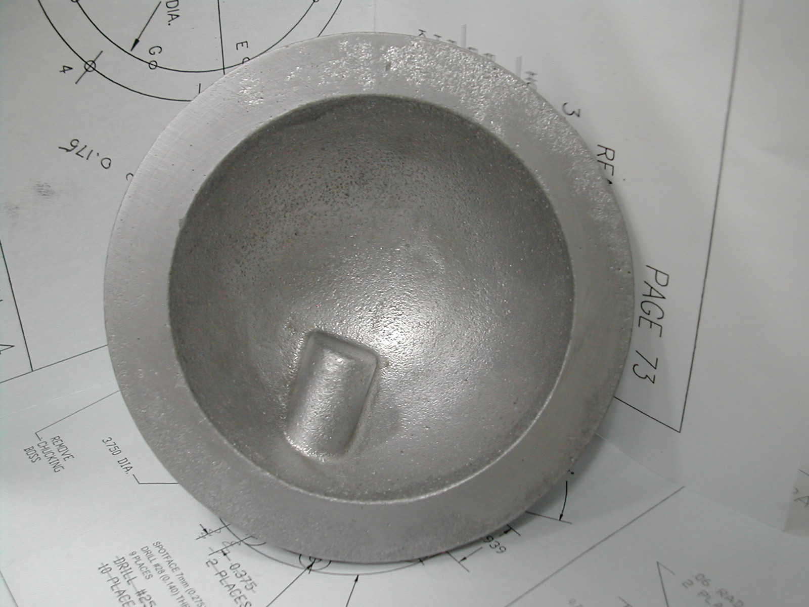 Castings are always fun to work with and this one was no exception. The casting was fairly high quality, machined nicely but had a little bit of porosity.
The first step to prepare this casting was to flatten the rear surface on a surface plate with some wet-dry sandpaper. Finish isn’t important – just make sure it’s flat and there’s no need to clean it up completely.
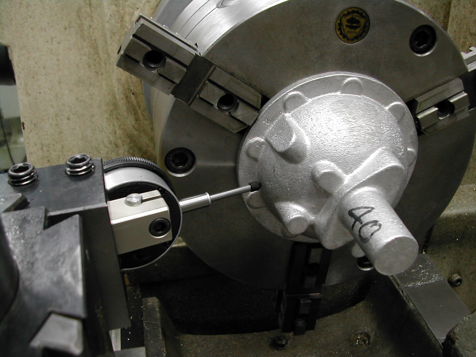 The nice flat rear face now fits securely against the chuck. I’m using my three jaw chuck because it has an Adjust-Tru back so I can center the cover. If you don’t have one, chuck it up in a four-jaw. I’m also dialing in the actual bowl portion of the cover, not the rim which will be machined. We want the rim concentric with the bowl.
 With the cover chucked and centered, I center-drilled the machining boss. I want to get a live center in the end before taking and large cuts since the rim is only holding on less than 1/8″.
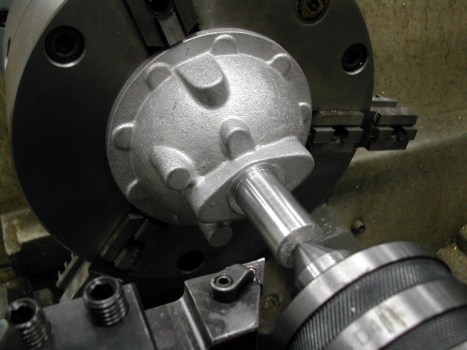 Now that the cover is really secure, I’m machining the boss down to an accurate size to fit in a 5C collet. I don’t remember what size I ended up with, but take a minimal amount off to use the largest collet possible. You don’t want the cover breaking off the boss prematurely when boring the 0.750″ hole later.
You might ask why I didn’t just chuck on the boss in the first place and skip the previous steps. Since the boss has draft on it, I didn’t want to take the chance that the tapered boss might work itself loose in the jaws before machining was finished.
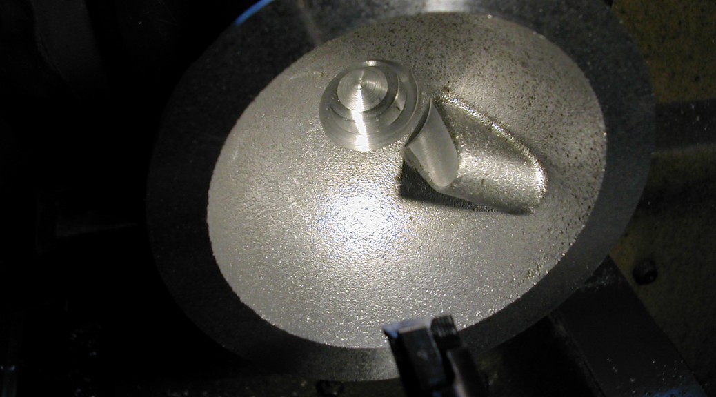
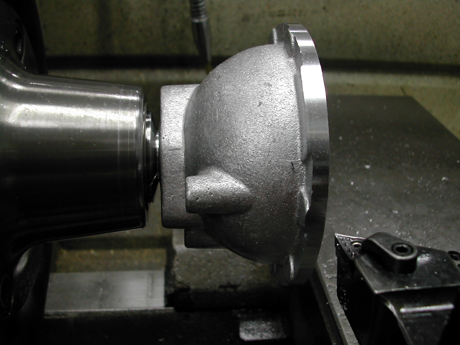 The cover is now turned around and securely mounted in a 5C collet for the remainder of the operations. First off is to turn the OD down to 4.187″…
 …and then face the flange to thickness. I assumed the 0.156″ dimension was to the bottom of the spotface on the mounting bosses so I kept the thickness about 0.020″ over this to give a nicely defined spotface.
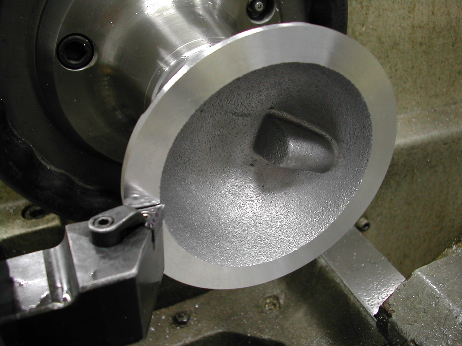
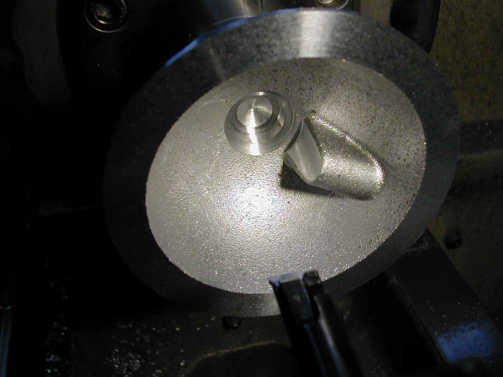 Next came the internal bores. I started with a 1/2″ drill and worked up from there. Don’t forget to cut the distributor boss to clear the 2.00″ diameter on the air horn, and you’ll probably have to make a small c’bore for the 1.166″ diameter as well. Make sure the 0.750″ bore goes well past the finish height of the cover.
 The recess for the air guide rim finished up the lathe operations on the cover. At this point, a hack saw removes the machining boss now that is has fulfilled its purpose. Hopefully if the 0.750″ bore was deep enough, you’ll have a hole in the center of the carb mounting flange.
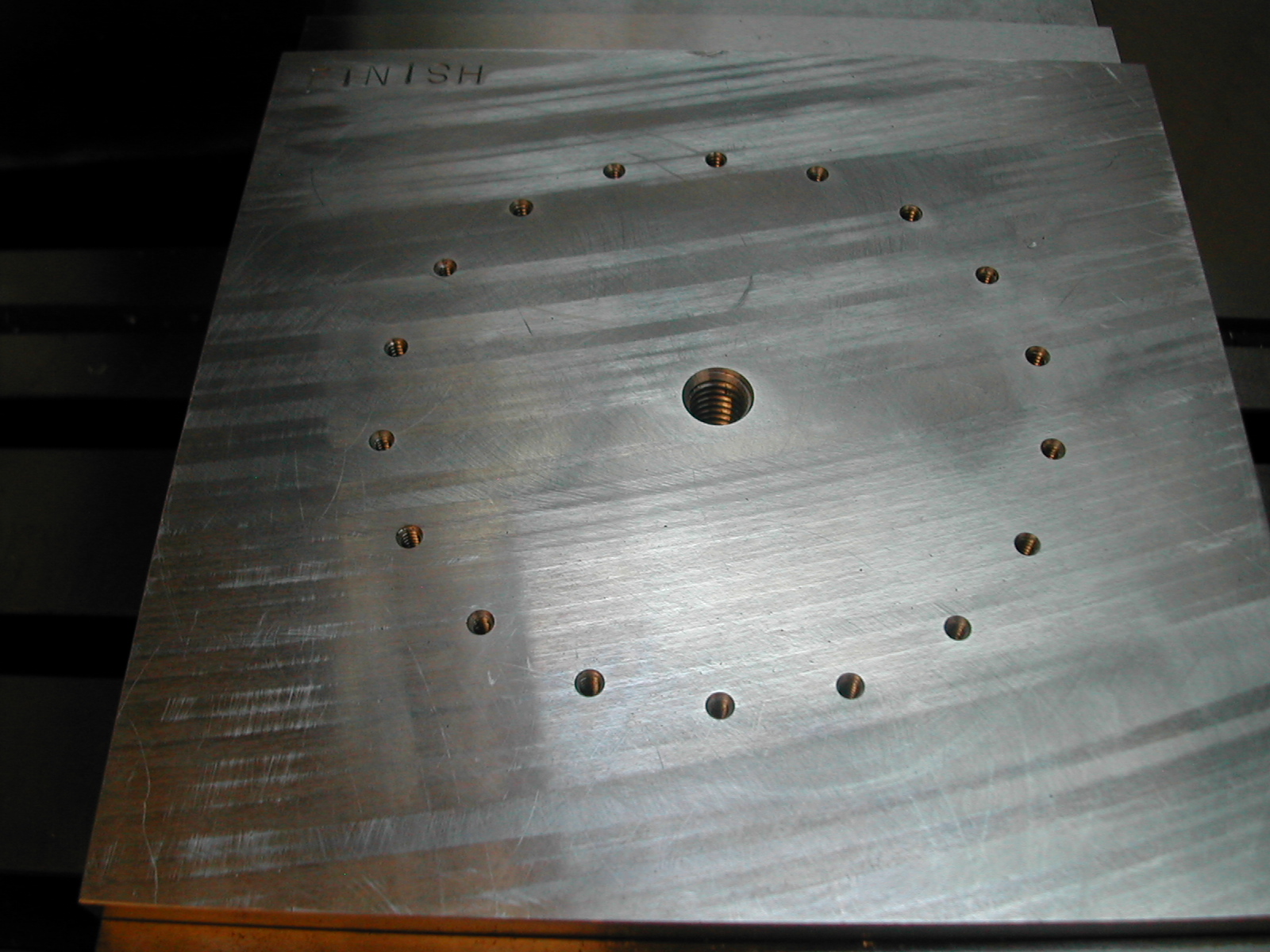 This tooling plate was previously used for the mill work on the front cover. Since it was to be used for both the front and rear covers, the 18 holes alternate between #4-40 and #6-32. The center 3/8″-16 tapped hole goes all the way through (notice the stamped “Finish” identifier on this side).
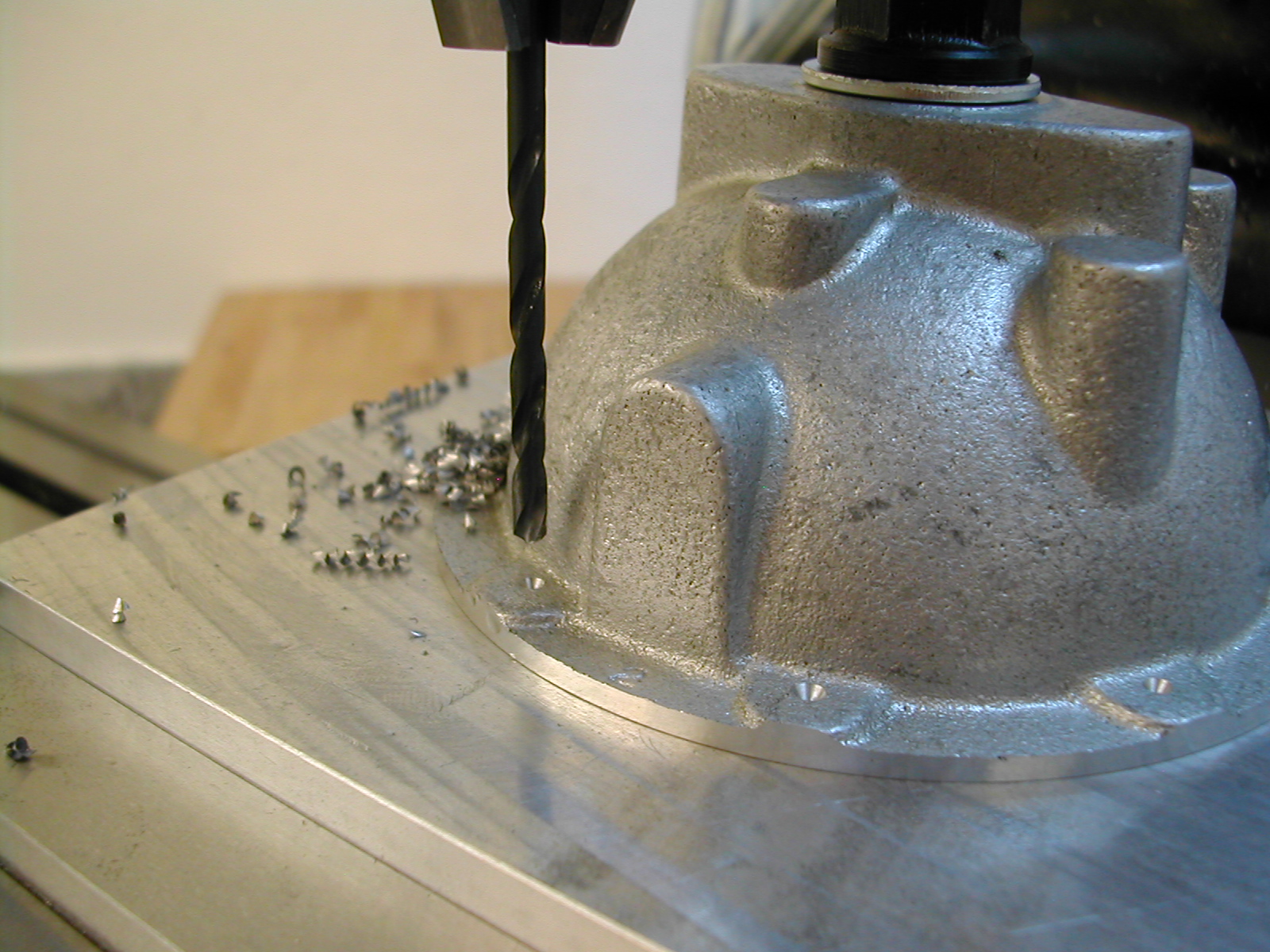 The tooling plate was flipped over and the rear cover was affixed with a 3/8″ clamp stud and nut. Since this is a casting you’ll want to take your time and make sure you get it alinged to minimize any imperfections. I looked at both the carb mount flange and the distributor boss to try and get both the carb studs and distributor bore to appear “centered” later on.
With the cover lined up, inidicate the outside rim to center it and then proceed to center-drill and drill the 9 screw clearance holes.
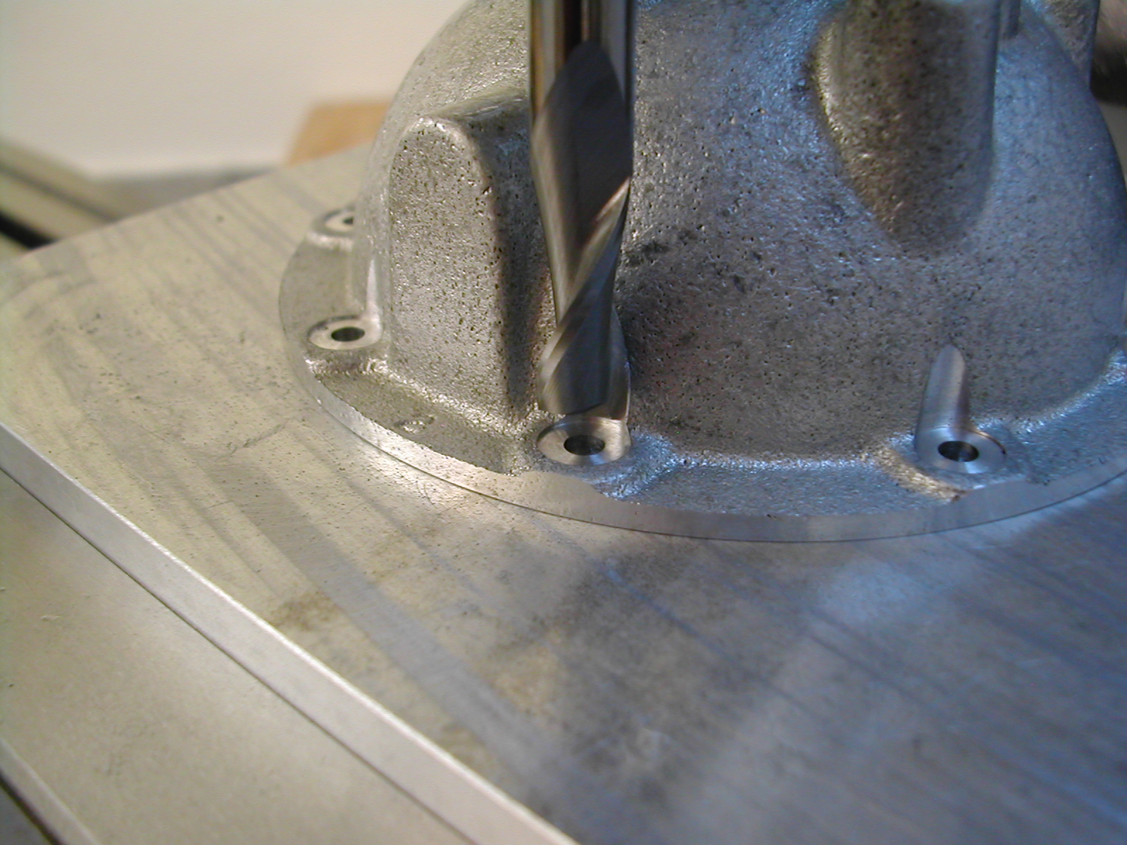 Since I’m using NAS620-C6 washers under the #6 SHCS on the cover, I spotfaced with a 5/16″ endmill.
 Next, I spotfaced and drilled and tapped for the #6-32 distributor lock.
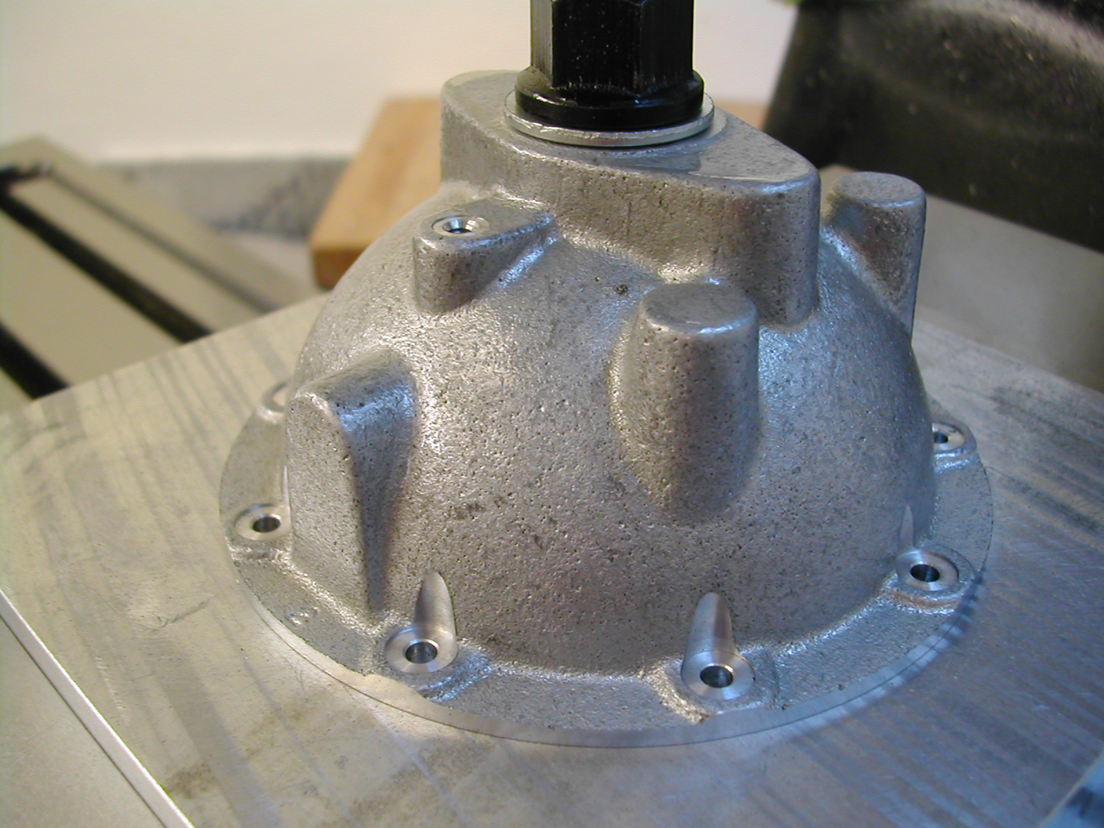
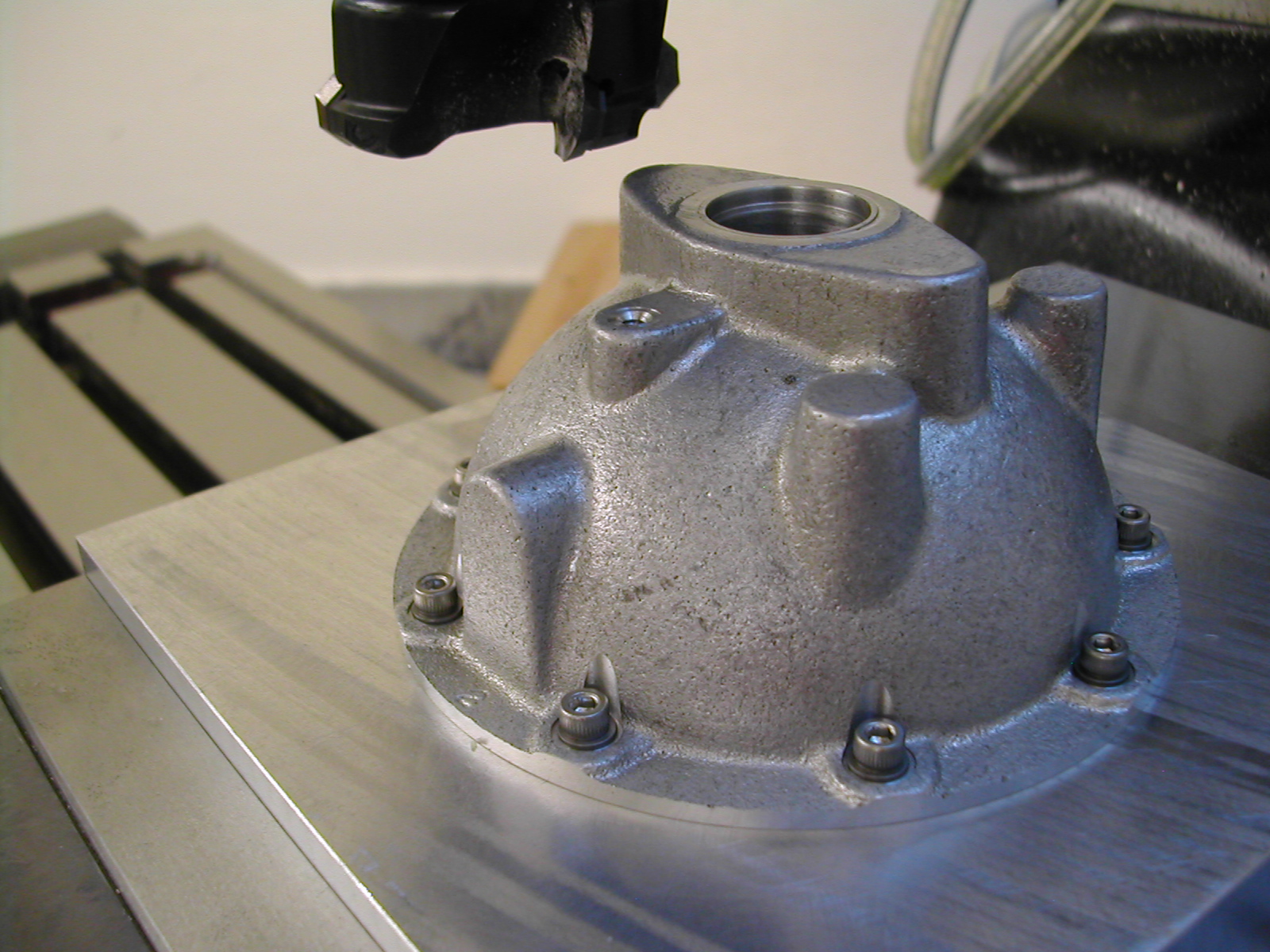 The clamp stud was then removed and the tooling plate flipped to the finish side. The cover was affixed to the tooling plate using the 9 #6-32 screws and then indicated around the rim for center. A face mill was then used to mill the carb mounting flange to the finish height.
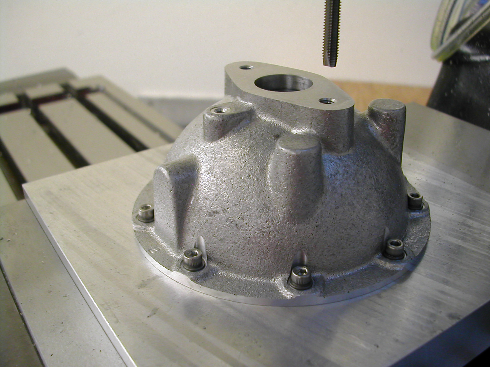 With the carb flange milled flat, the two carb stud holes were drilled and tapped. I thought the 1/4″-28 studs were completely out of scale and since I was making my own carb mount, I switched these to #10-32.
At this point, you may want to attach your carb mount to the casting and profile the outer perimeter of the carb mount and make any “adjustments” to the carb boss permieter so they match nicely.
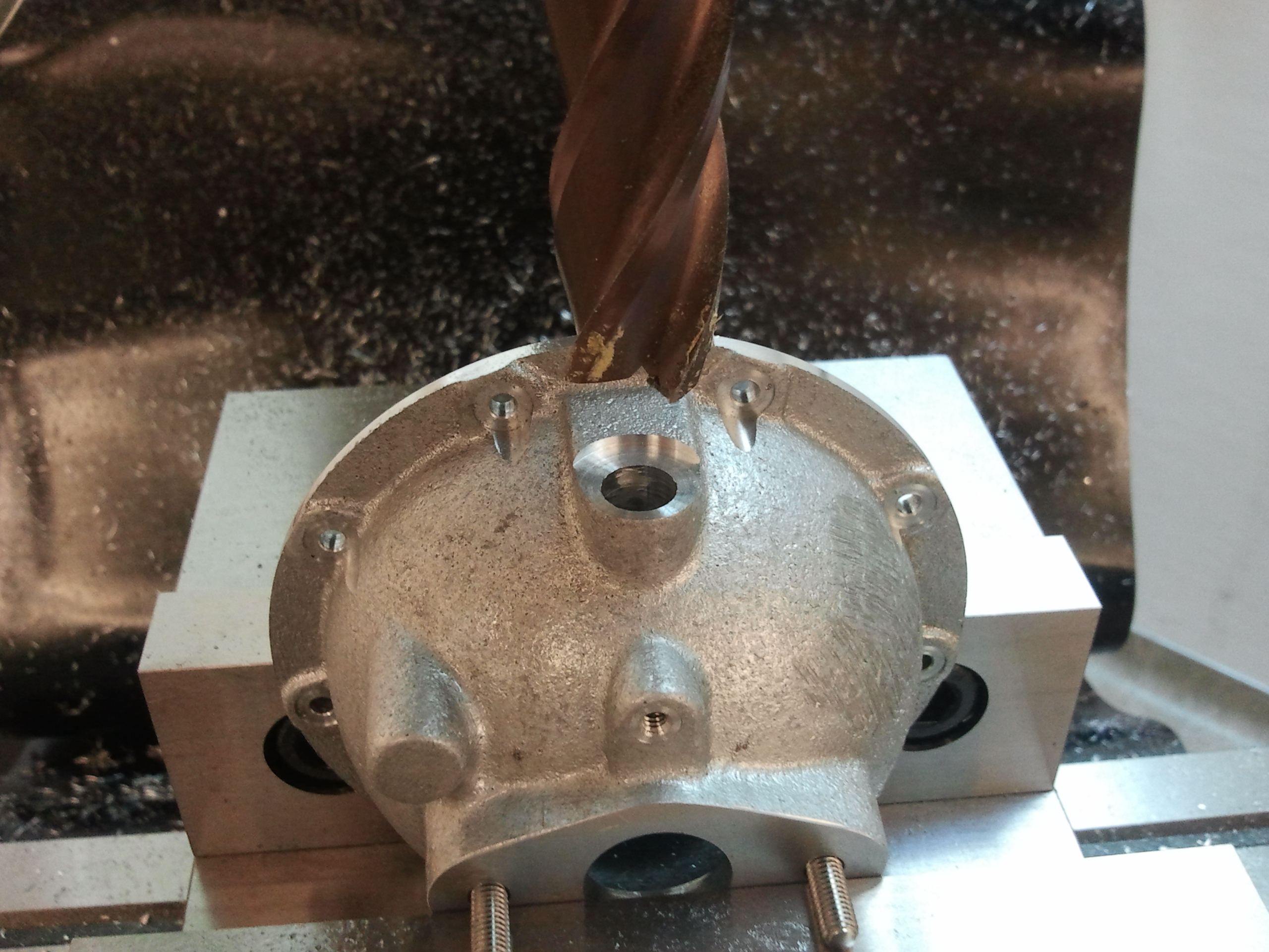
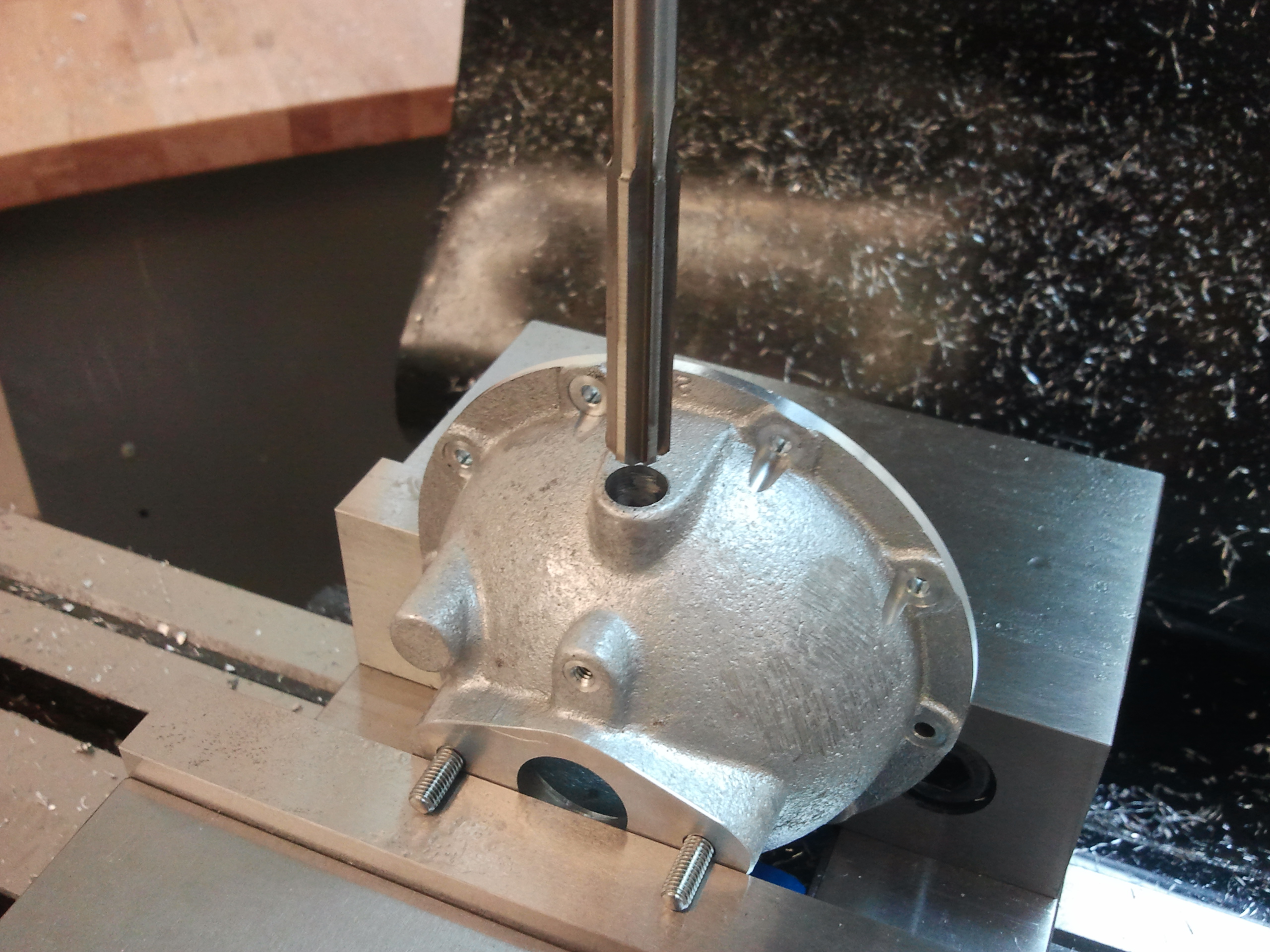 The carb mount studs make it easy to align the cover for drilling the distributor bore. With the studs resting on the vice jaw, all that’s left is to indicate center in X and the cover face in Y and proceed to drill and ream the distributor hole.
Finally, a 3/4″ end mill spotfaces the distributor boss to the finish height completing the work on the rear cover.
Disclaimer and License
All material, including the CAD drawings, relating to the construction of the Hodgson Radial presented on this site is free to use any way you see fit. However, no guarantees are made regarding the accuracy or correctness of the material presented here.