
- Hodgson Part 005, Bearing Retainer Plate
- Hodgson Part 007, Front Cover
 The front cover started life as a 125mm diameter by 300mm piece of Aluminum 7075-T6. I bought a stick of this long enough to make the cover, crankcase, rear seal plate, air guide, impeller, and a few fixtures. The diameter was needed to accommodate the crankcase so I did end up wasting a little material on the other parts.
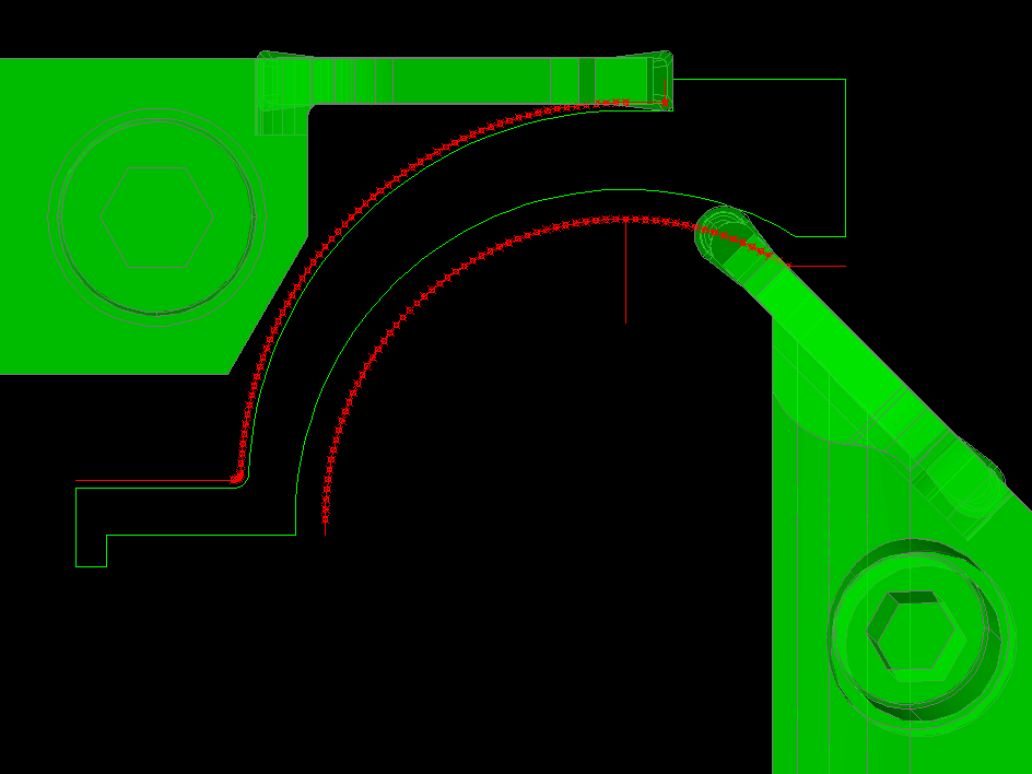 I changed the internal profile of the front cover from the faceted design in the drawings to a smooth curve to match the outside profile. I laid both the inside and outside profiles out in AutoCAD, then created a couple of Excel spreadsheets (part 007 inside path, part 007 outside path) to help me turn these on my manual lathe.
I’m using a Korloy MGEHR1616-3 toolholder with a MRMN300-M insert to profile the outside and a MGIUR4025-3 toolholder with a MGMN300-M insert to profile the inside.
 I’ve previously chucked up the stock and drilled a 3/4″ starting hole. Here I’m facing the end with my profiling tool to set the length (Y-axis) datum.
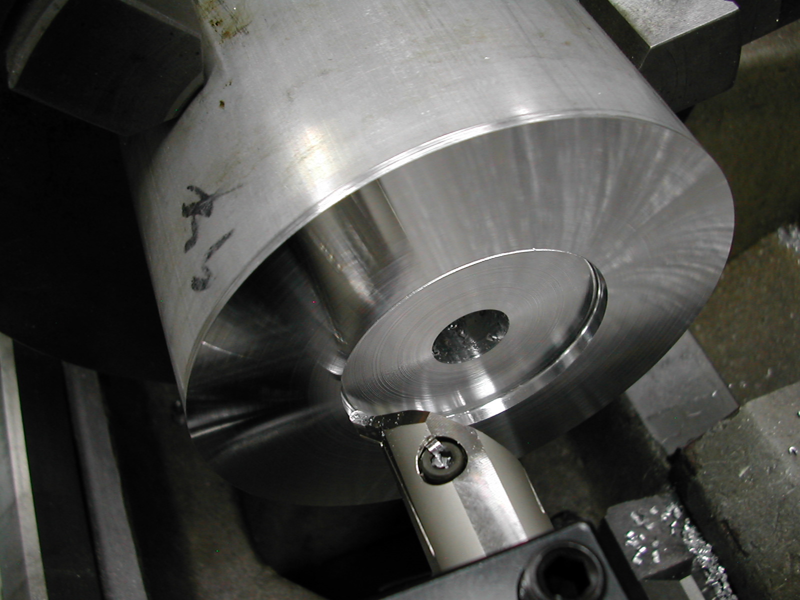 Next, I made a little test bore where I could measure the I.D. and set the X-axis datum.
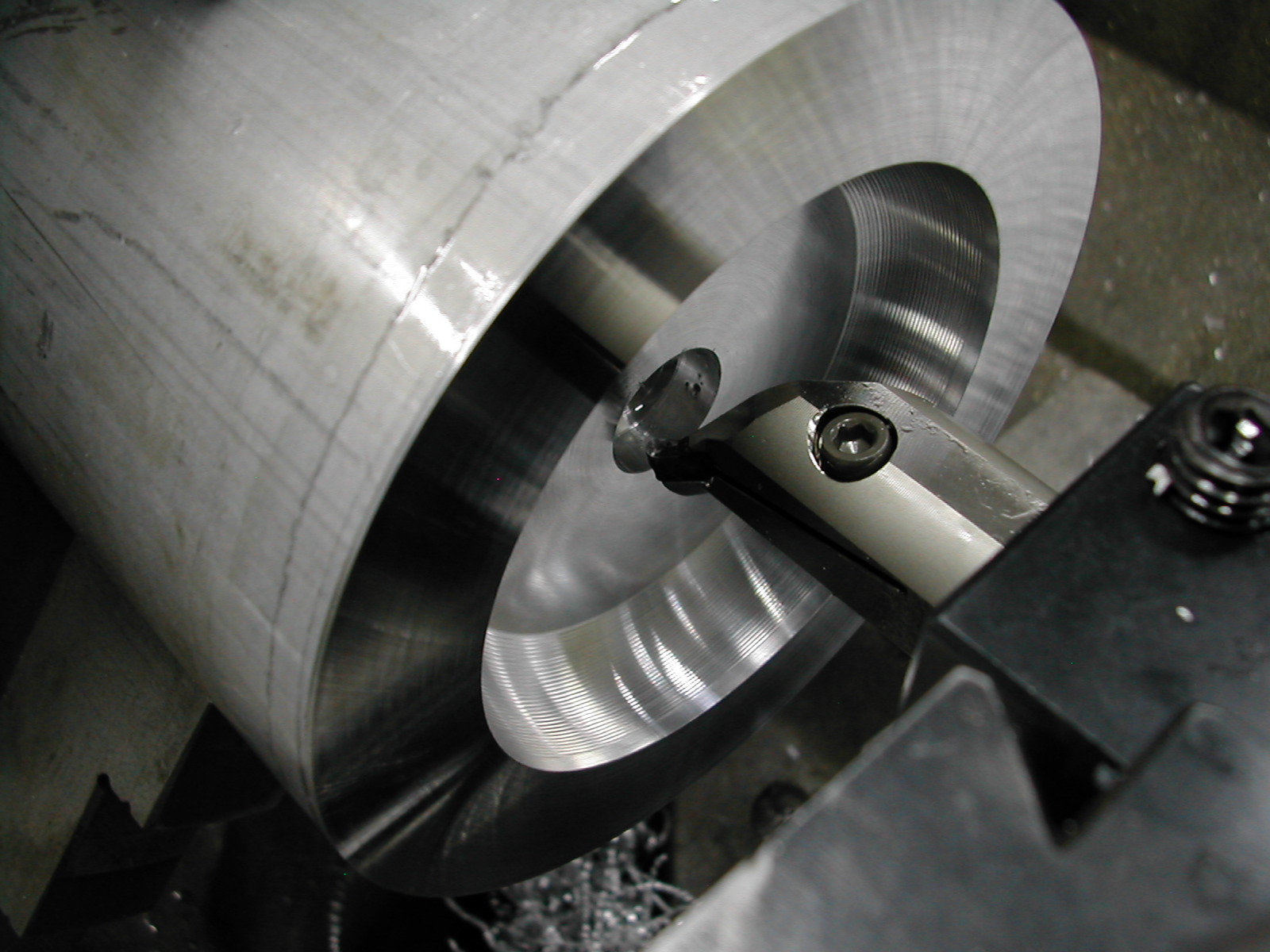 With my tool preset, I proceeded to follow the toolpath I generated by starting at center, setting the depth of cut, and then feeding out till I reached the calculated diameter. This was repeated until I reached the bearing flange depth.
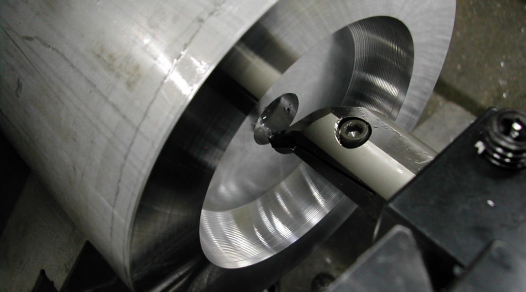
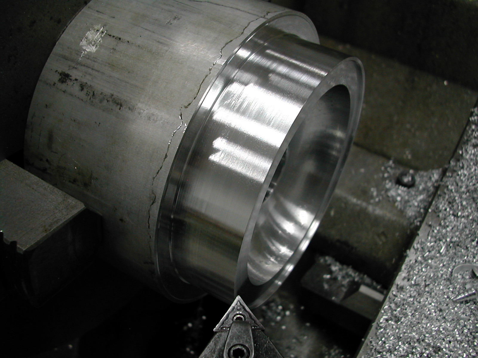
 Once at the bearing flange depth, I plunged in to the next depth at the curve radius point (Ø2.000″) and faced in to the bearing boss side diameter and then out to the outermost diameter.
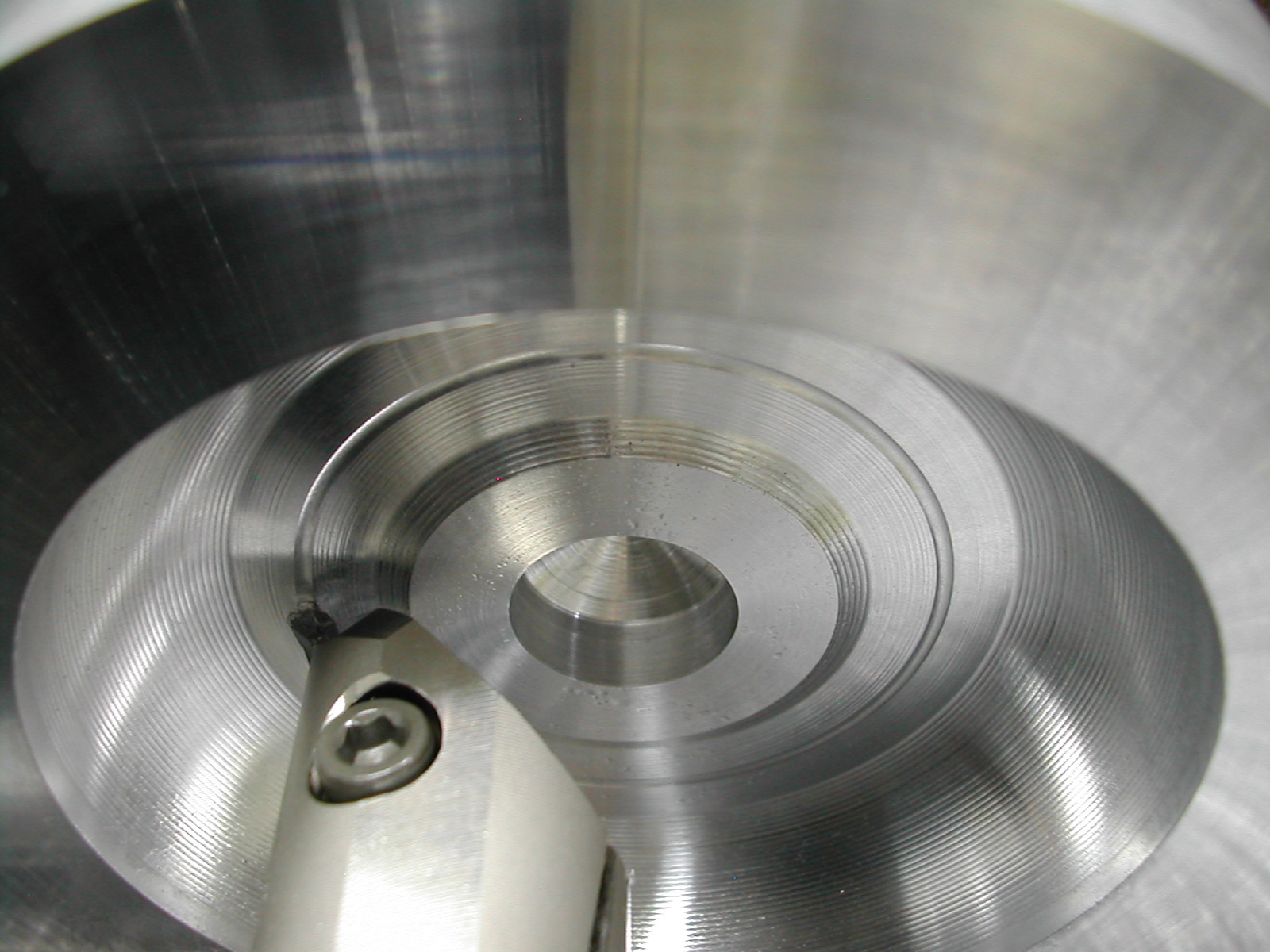
 The internal profile is roughed out at this point. The scallop height is actually much less than it appears in the photo at less than 0.001″.
 With such a small scallop height, it only took about 5 minutes total with a scraper and then 320, 600, 1000, and 2500 wet-or-dry paper to finish the inside.
 A boring tool makes quick work of the locating flange. Be sure and fit this to your crankcase.
 On to the outside with the first step of turning the 4.187″ finish diameter.
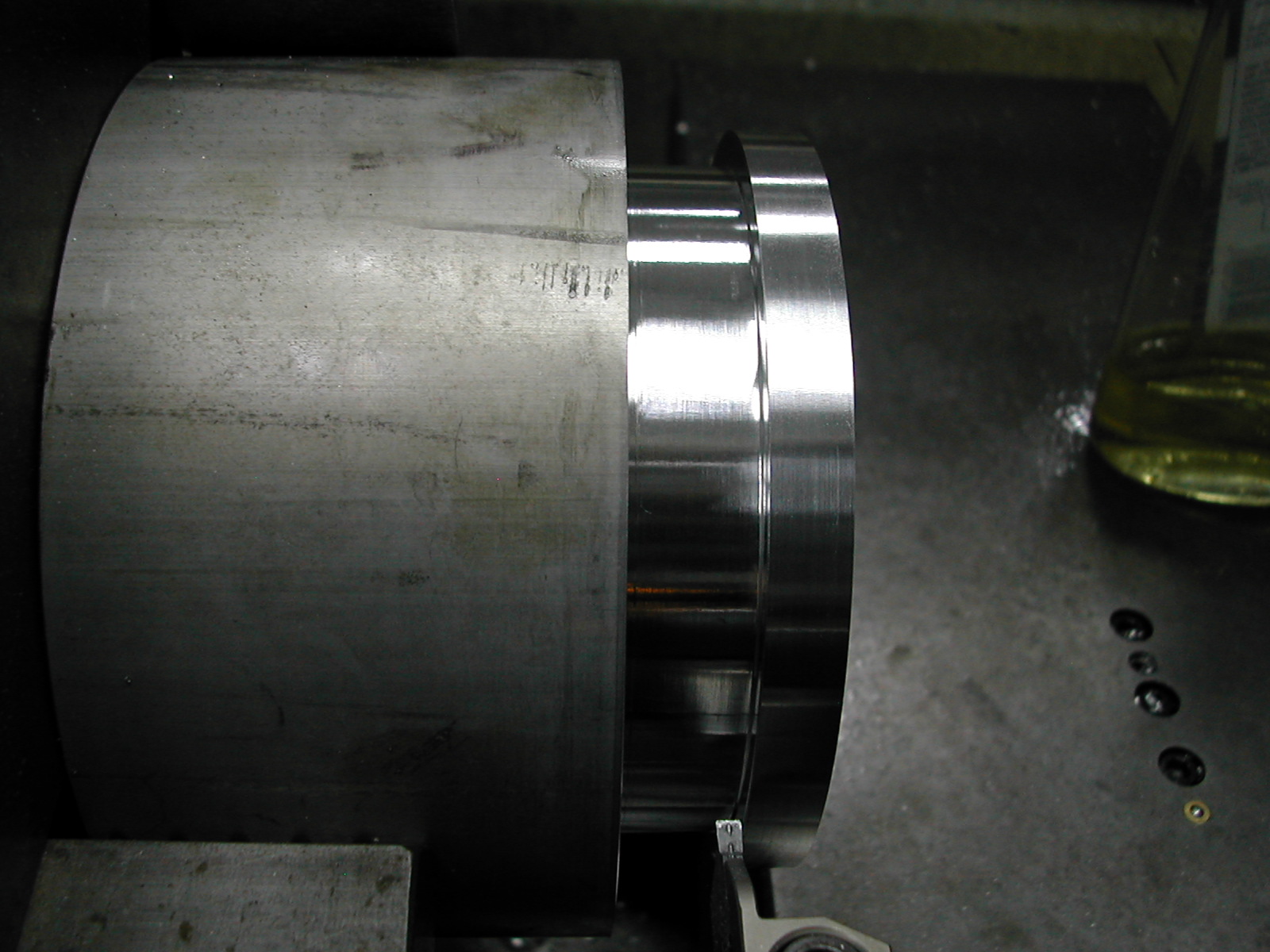 To set the datum for the external profiling tool, I’ve turned a small groove with the tool. I can now measure the groove diameter and the flange width to set the tool offsets.
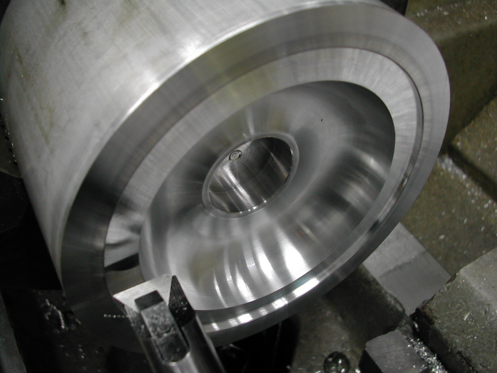
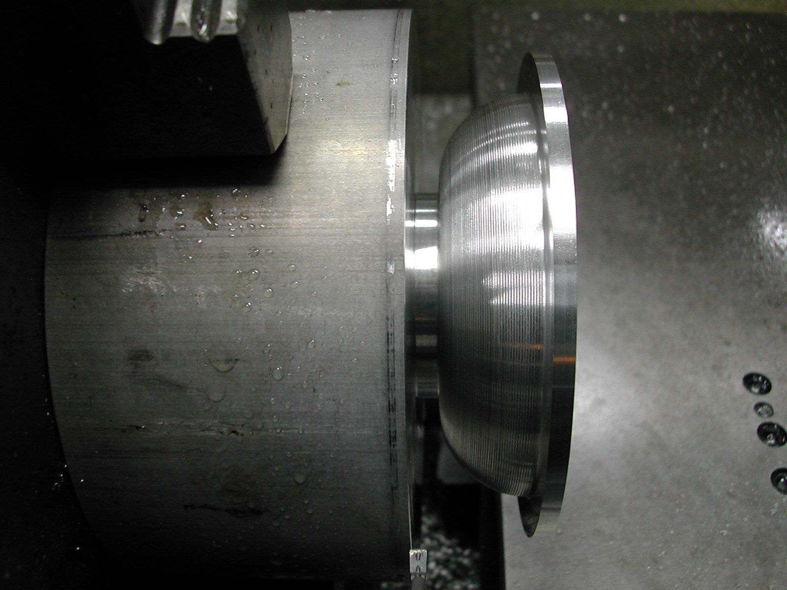
 I’m midway through profiling the exterior of the front cover by using the tool as a part-off tool. I.e. setting the carriage location and plunging to the proscribed diameter.
Every once and a while, I’ll widen the groove all the way over to the left edge so I don’t have to feed in so much on every plunge. I’ve just finished doing that in this photo.
 The smaller corner radius on this insert verses the one used on the internal profile resulted in a scallop height of 0.0035″.
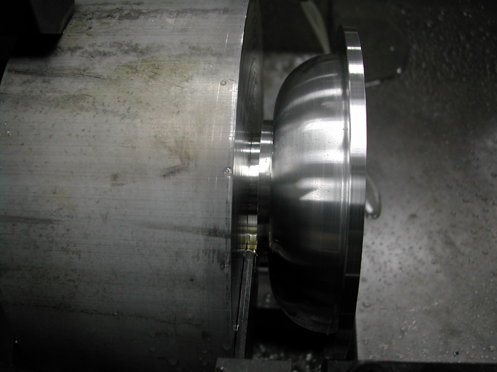 It took a little bit longer to remove the scallops using the same procedure as the inside due to the larger scallop height and the tight quarters down at the bearing flange location.
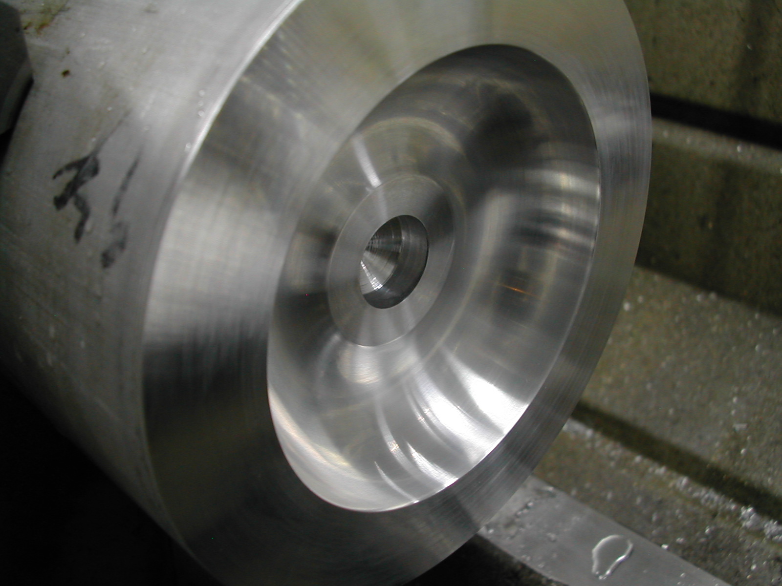
Still, it only took about 10 minutes before I was ready to part the cover off from the stock. I’ve left the bearing flange area long and I’ll clean it up to length later when I go to the mill.
There’s some dried coolant on the part in the photo, but the surface finish left by the 2500 grit paper closely approximates the as-turned finish on the crankcase.
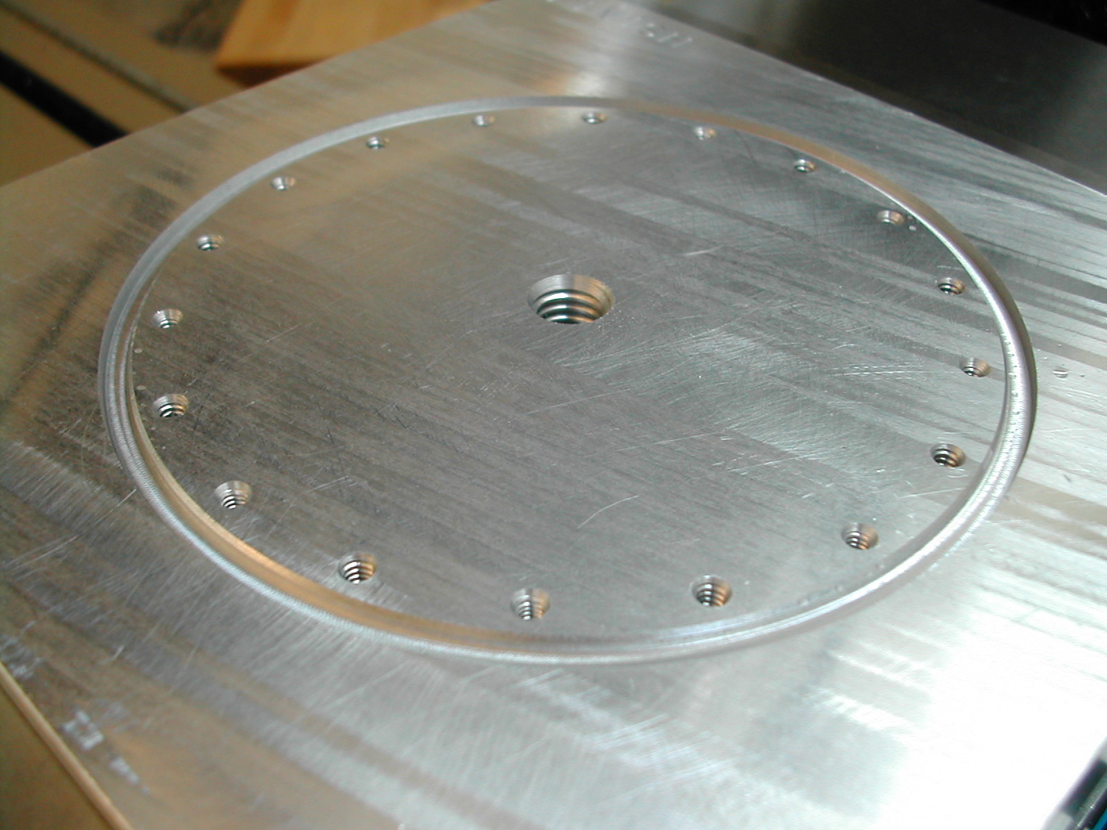 With the lathe work complete on the front cover, work moved to the mill. A tooling plate was clamped in the vise and nine each alternating #4-40 and #6-32 holes were added on the 3.750″ bolt circle of the crankcase to fit both the front and rear covers. A center 3/8″-16 hole was tapped through, and a groove was milled to clear the lip on the front cover.
In addition to the front and rear covers, this tooling plate will also be used to fixture the crankcase for its milling operations.
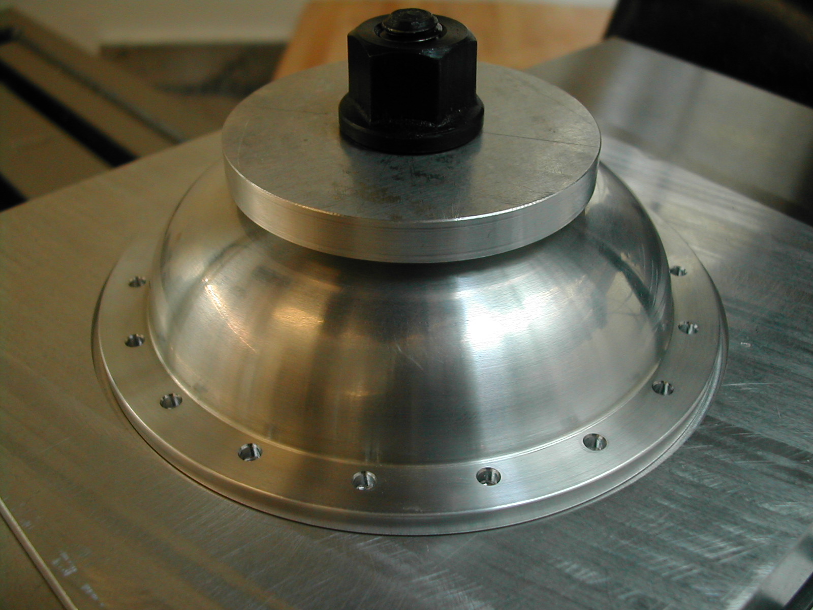 Here the front cover has been fixed to the tooling plate with a clamp stud and oversize washer in the central hole and the 18 #4 clearance holes drilled around the perimeter.
 Nine #4-40 screws are now inserted in the newly drilled holes to fasten the cover for work on the bearing plate retainer flange. Where the flange had previously been parted off long on the lathe, it is now milled to the finish height.
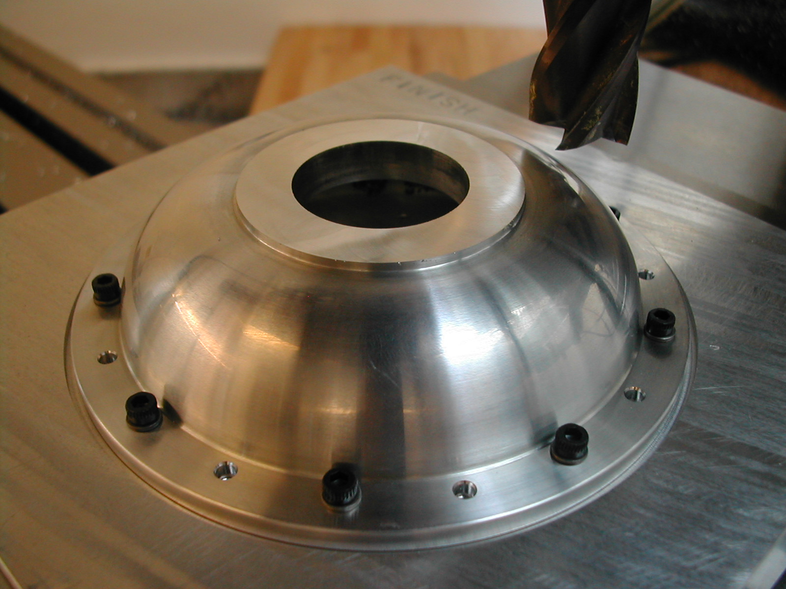
 The six #4-40 holes are drilled and tapped in the bearing flange. You’ll probably need to add a little bit of countersink to these holes to accommodate the small amount of the screw head that protrudes on the backside of the bearing retaining plate.
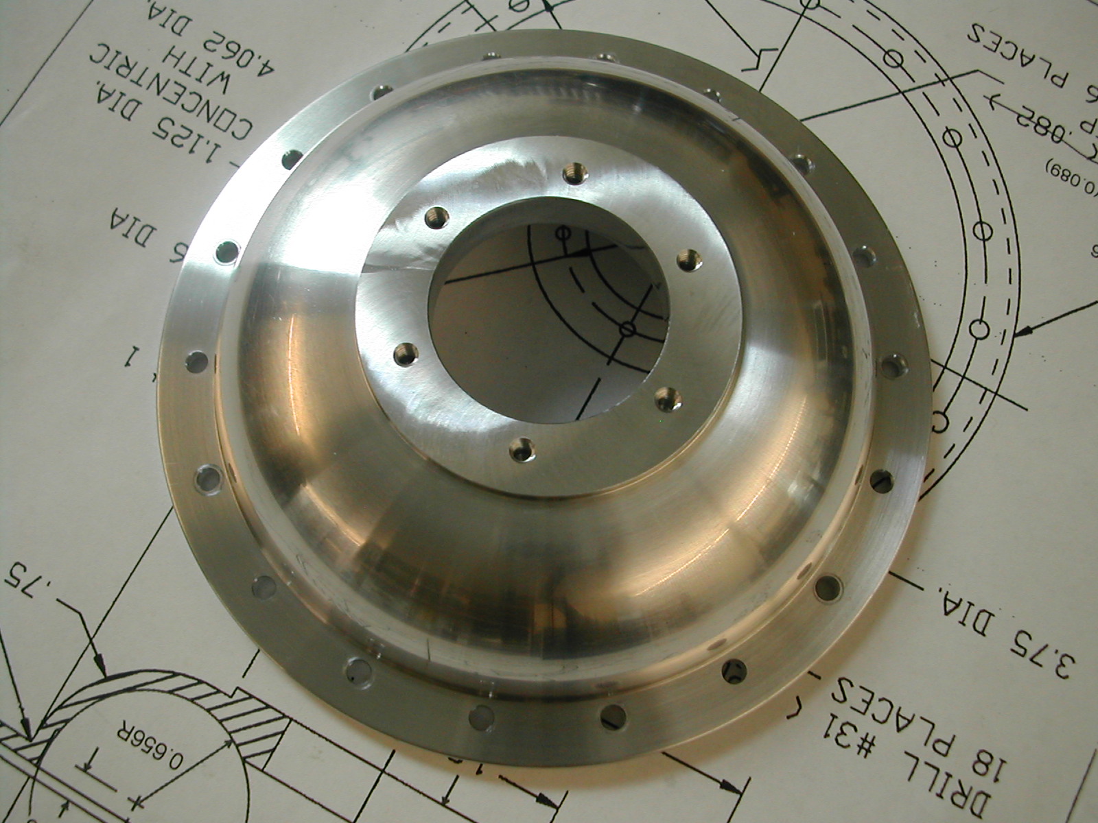
Here is the completed cover ready for installation.
Disclaimer and License
All material, including the CAD drawings, relating to the construction of the Hodgson Radial presented on this site is free to use any way you see fit. However, no guarantees are made regarding the accuracy or correctness of the material presented here.
Links Used On This Page
(CAD drawings are in AutoCAD 2010 Format)