
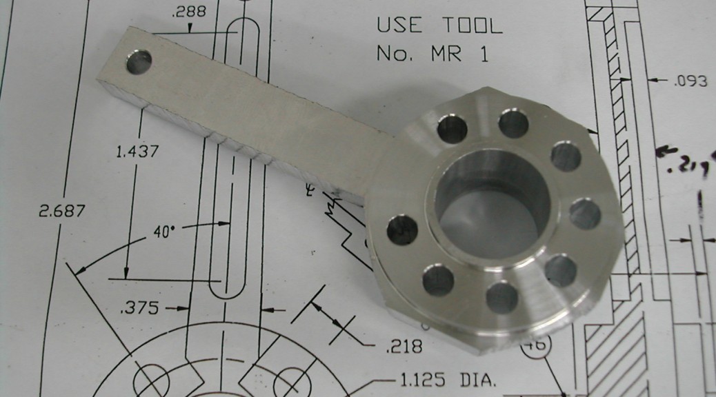
- Hodgson Part 045, Master Rod
- Hodgson Part 046, Main Rod Bearing
- Hodgson Part 047, Slave Rods
- Hodgson Part 048, Slave Rod Pins
 The master rod was made from a piece of aluminum 7075-T651 sawn from plate.
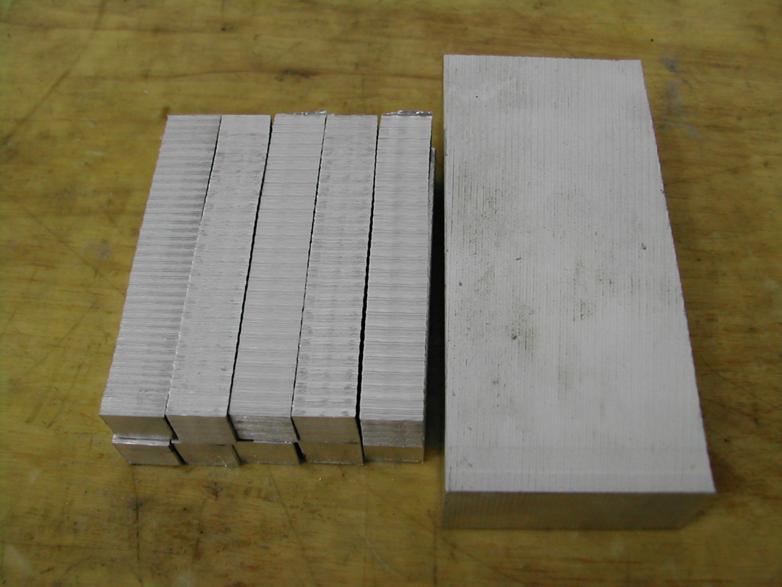
One master rod and ten slave rod blanks ready for squaring.
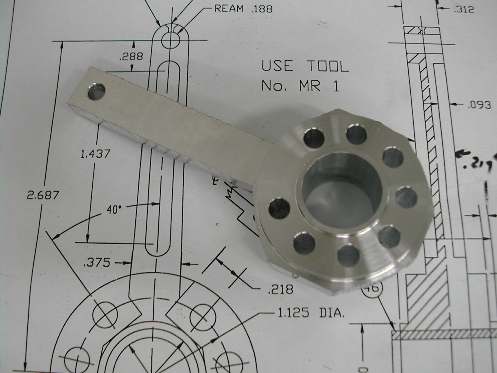
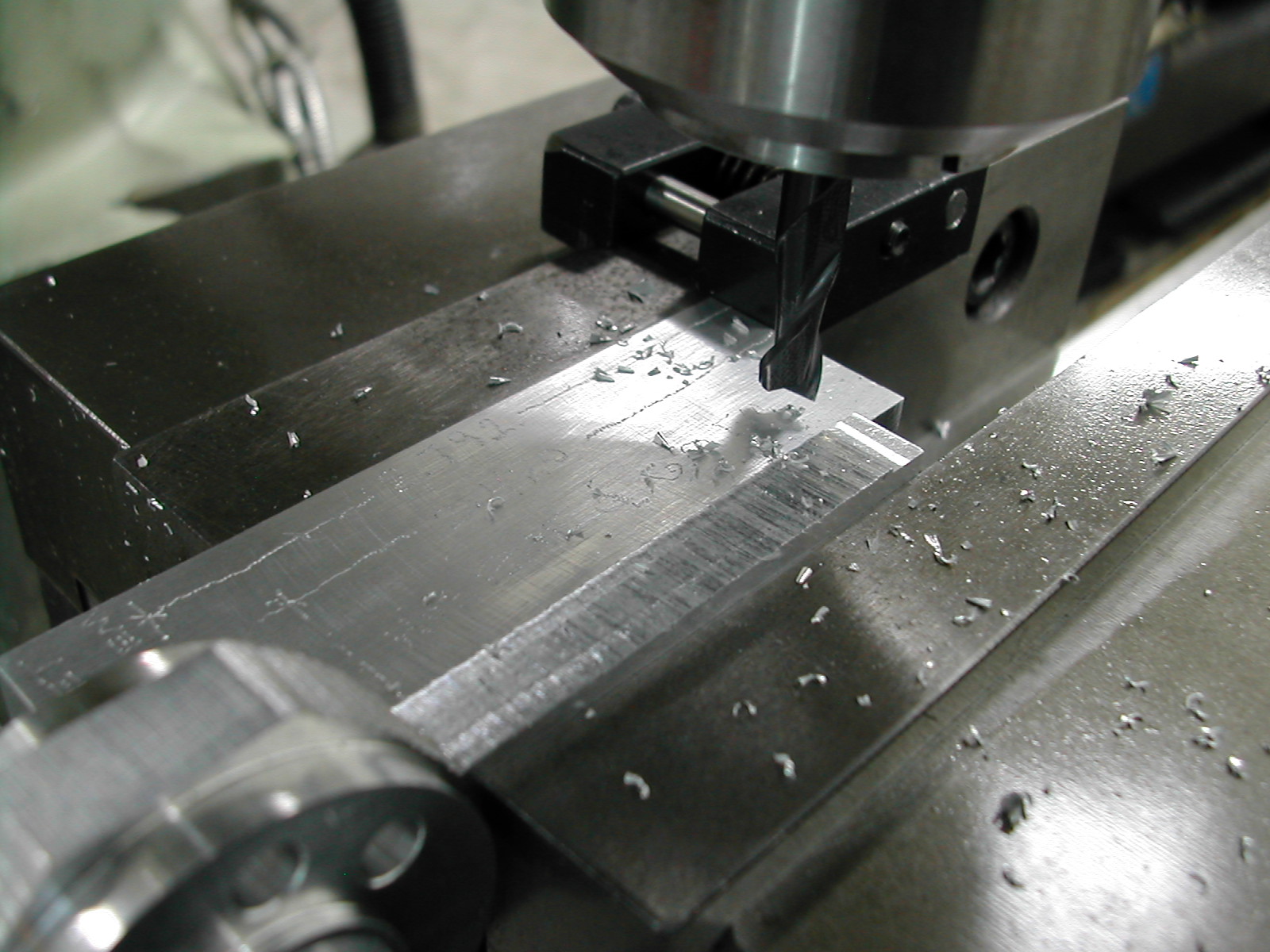
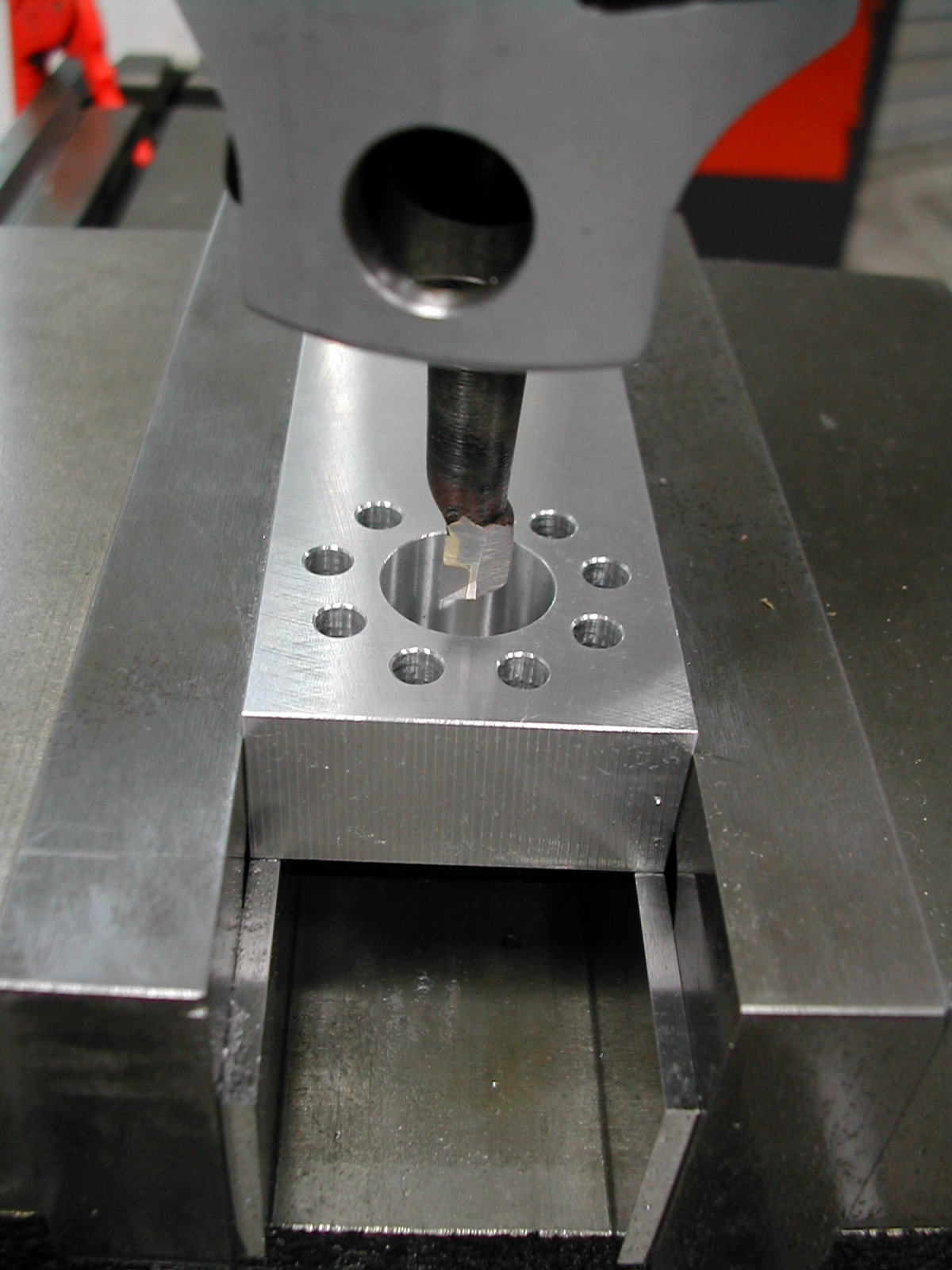 After the master rod was squared to the 0.750″x1.625″x3.750″ dimensions given in the process plan, the 8 slave rod pin holes were drilled and reamed to 0.1880″ for s slip fit on the slave rod pins. The master rod bearing hole was then drilled and bored to size in the same setup.
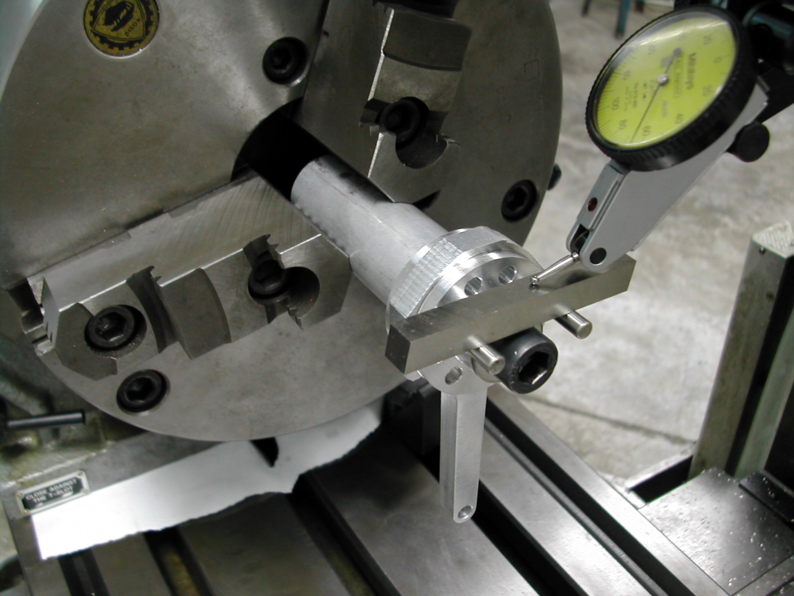
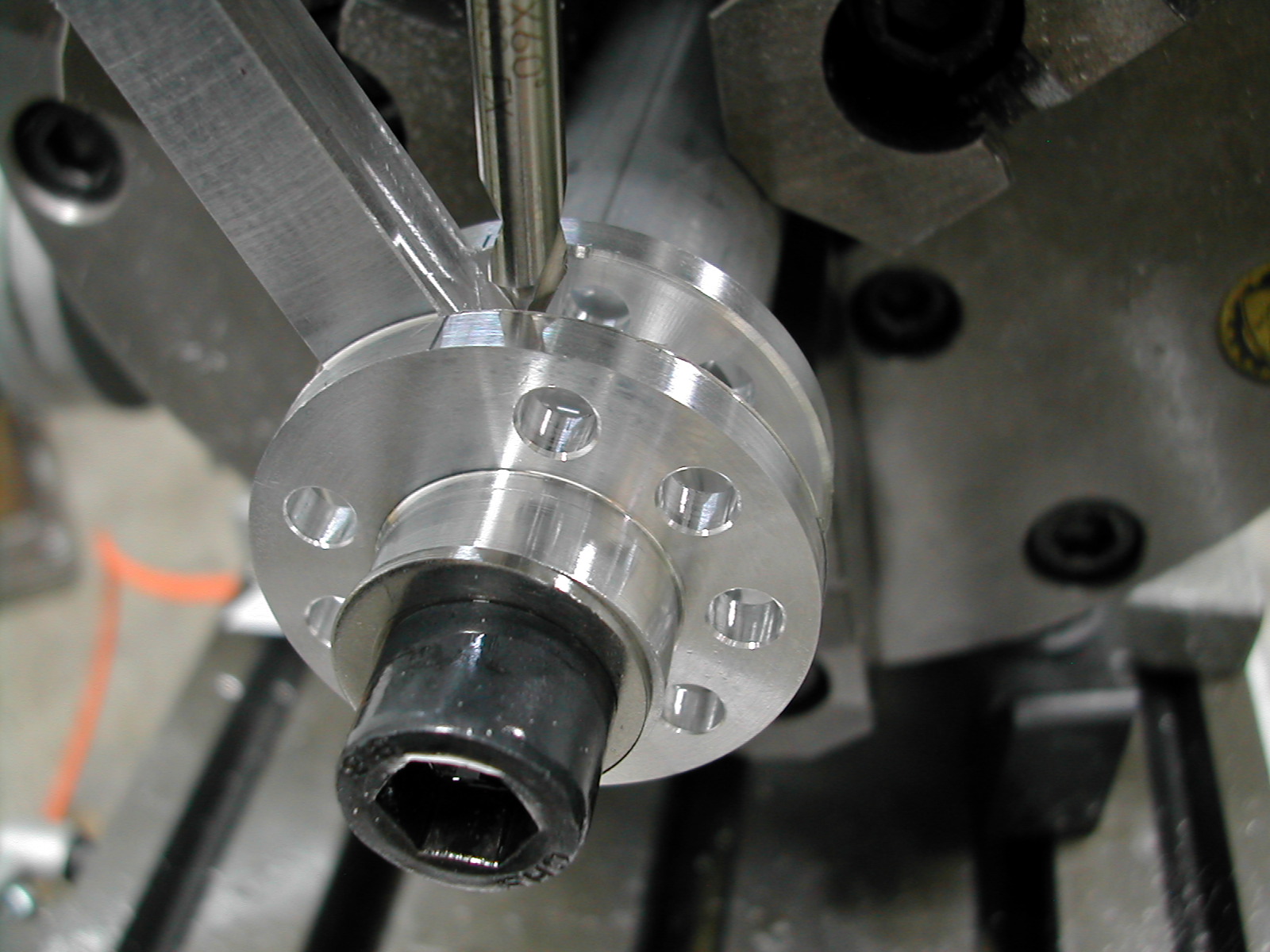
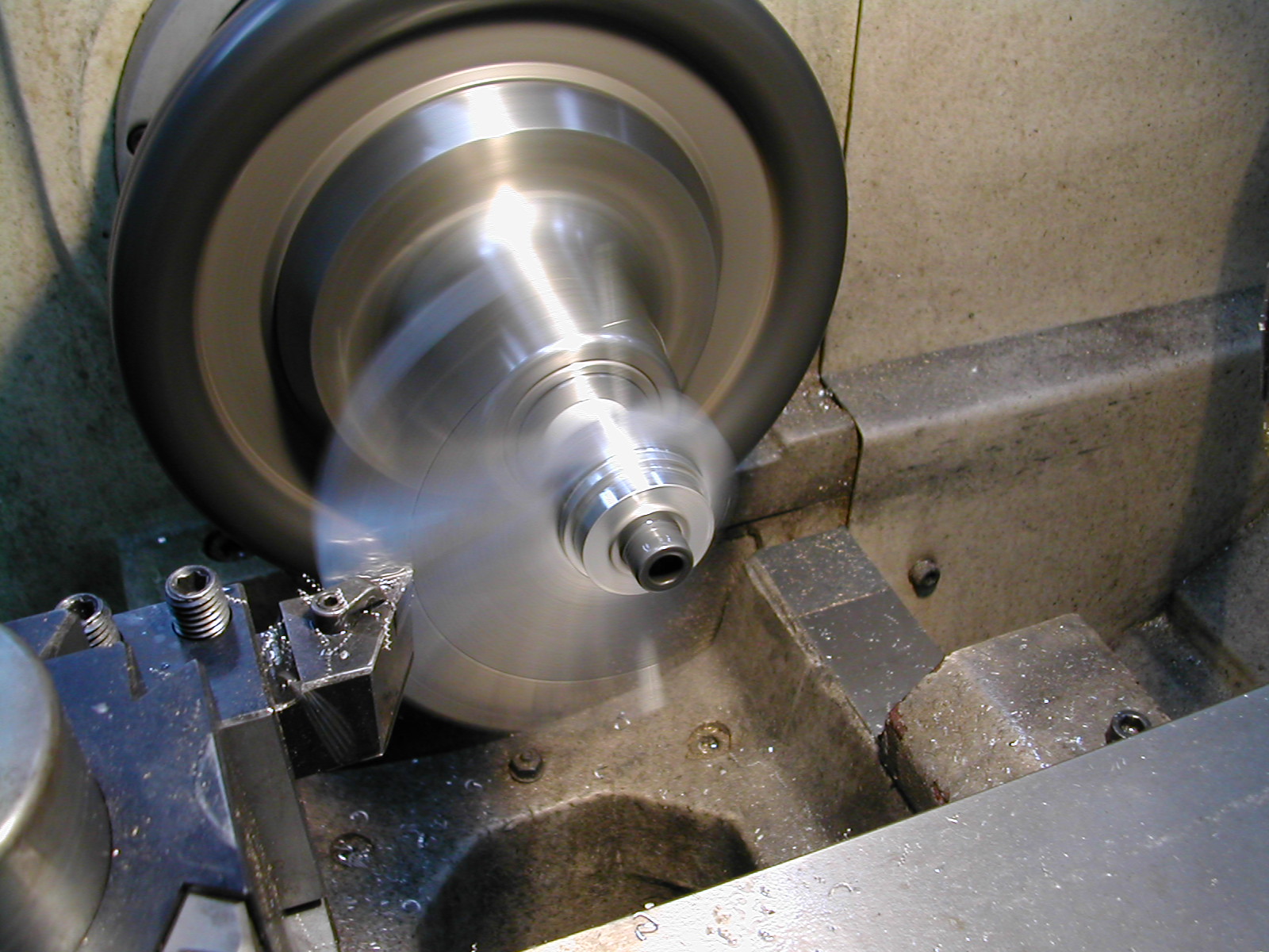 A spud arbor was then turned on some scrap aluminum stock in the lathe and the master rod blank mounted on it with an M8 SHCS. The first side was then turned down to the 1.500″ diameter dimension.
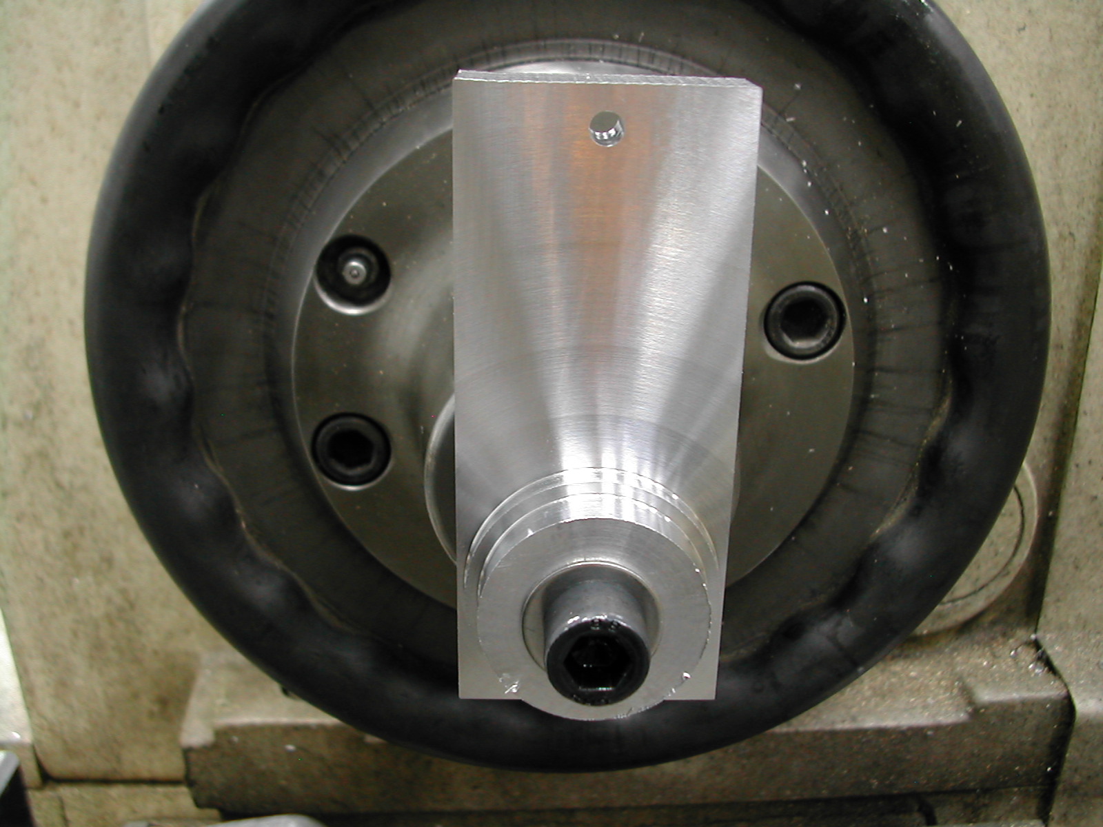 The process plans call for rough cutting the rod to shape and then performing this turning operation. I left the stock wide in the hope that any chatter generated due to the intermittent cut would hopefully dampen out before reaching the center finished area.
As you can see, this did not appear to be necessary as no chatter was evident in the finished surface, but I do think the intermittent cut was still helped by a wider area.
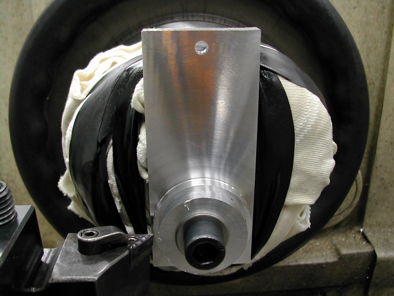 While turning the second side, I did encounter some ringing when I got down closer to the finish thickness of 0.312″. A shop rag taped behind the rod and pressing against it stopped all but a little chatter near the wrist pin hole.
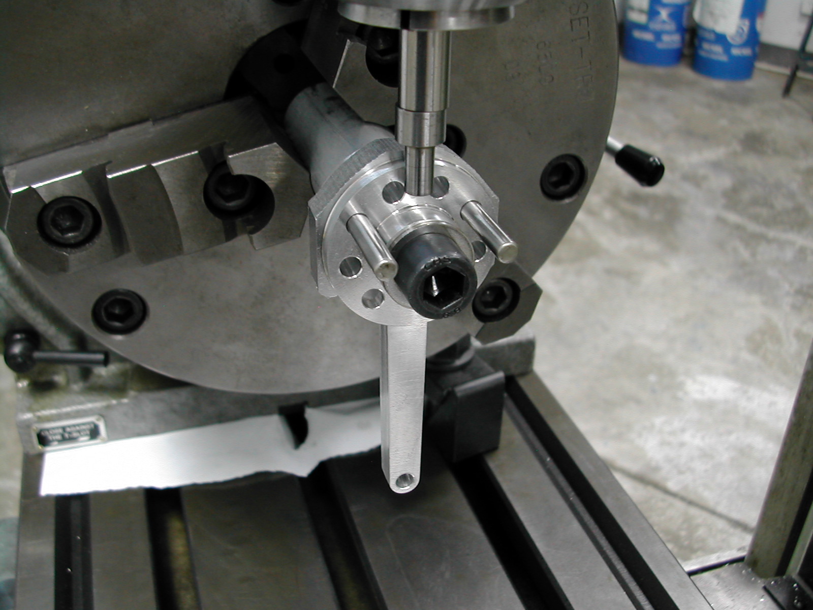
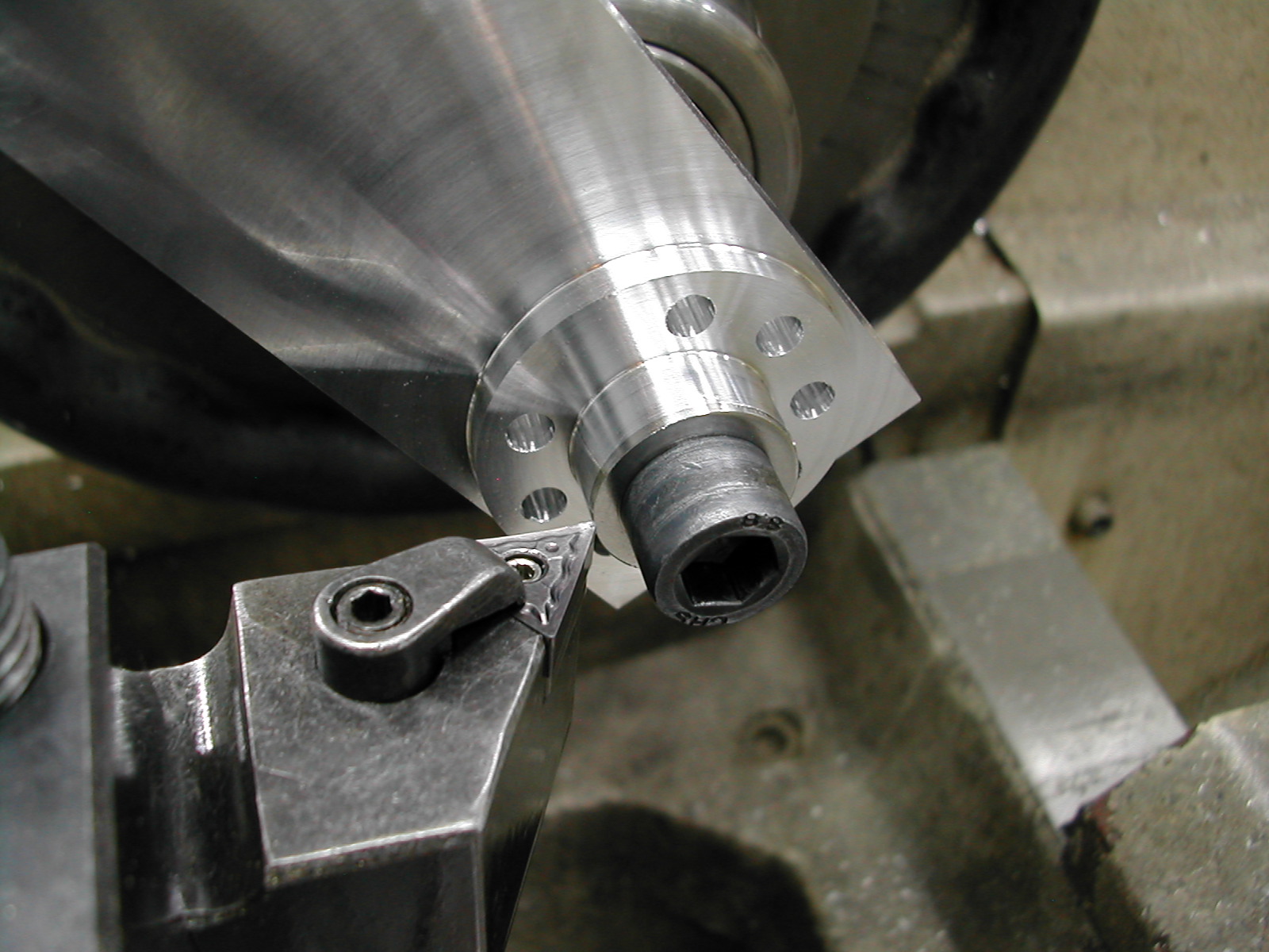 Here I’ve turned my clamping washer, the aluminum caul behind it down, and finally the master rod blank down to create the 0.790″ shoulder. Turning the caul down exposed the slave rod pin holes in the blank. After completing the shoulder, the master rod was flipped on the arbor, and the shoulder turned on the opposite side.
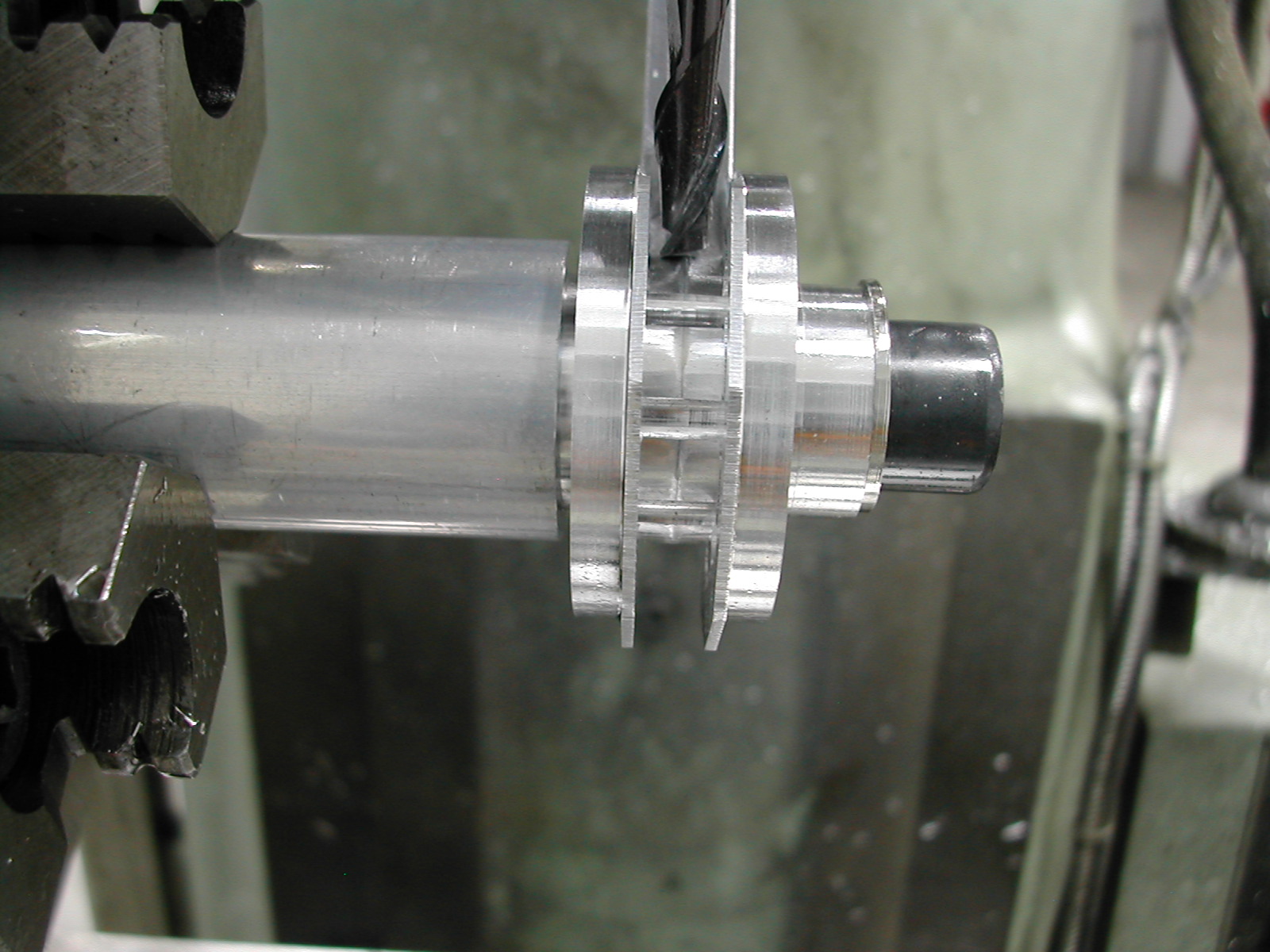
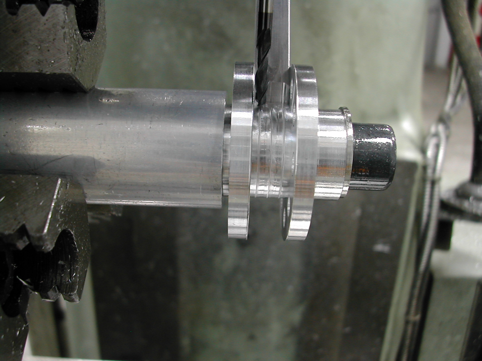
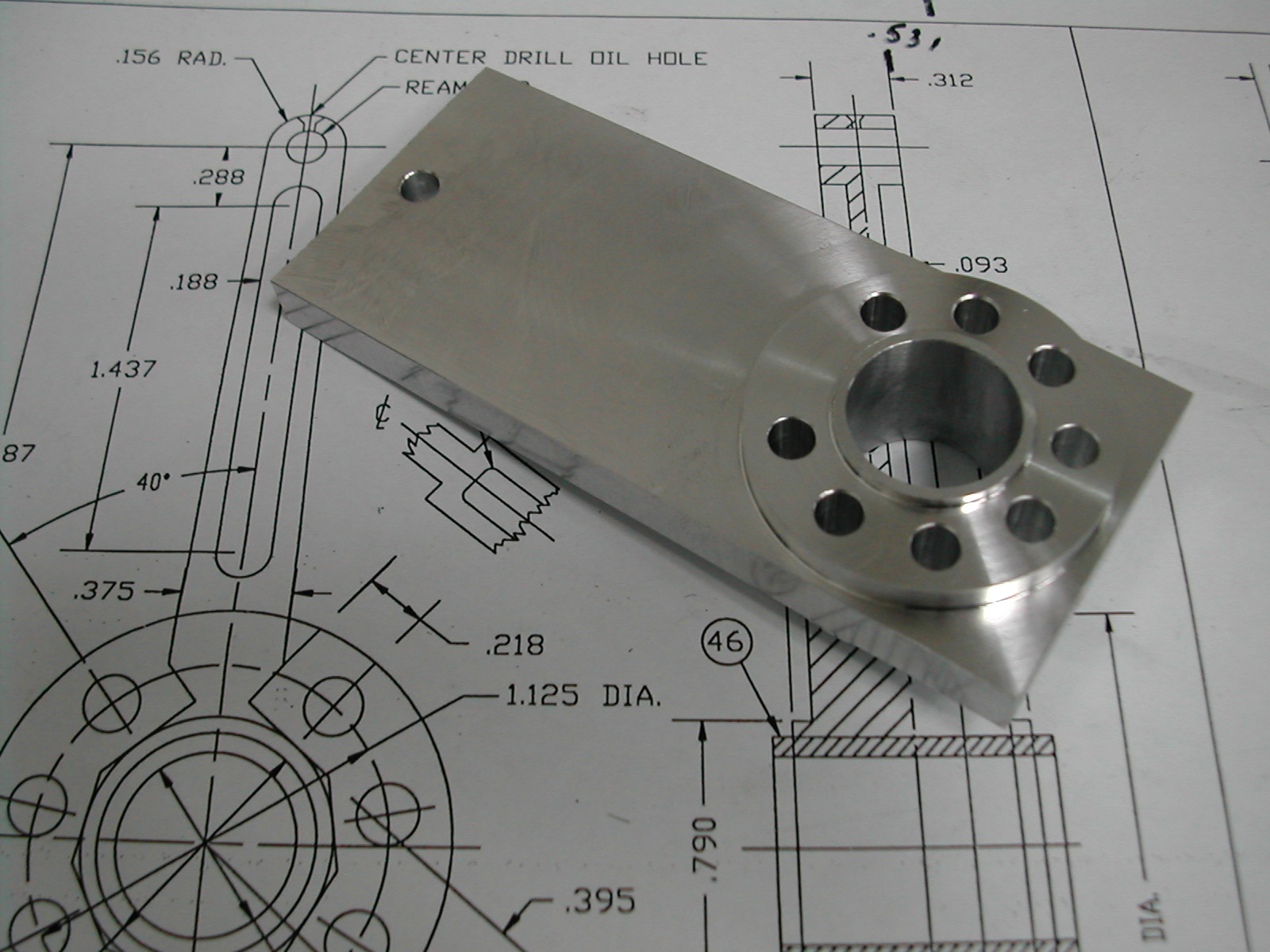 Here is the rod blank prior to bandsawing the waste. It’s already lost a considerable amount of weight and it’s going to get much lighter real soon.
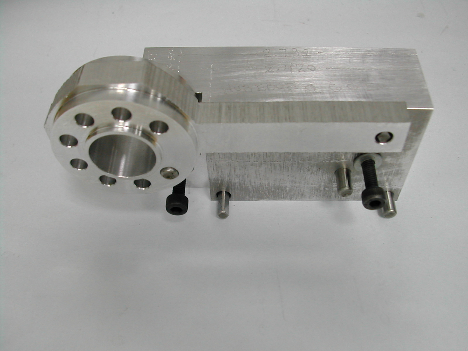
 Here’s the blank after the trip to the bandsaw. The rod neck has been roughed to shape and the corners have been knocked off from around the periphery.
 This is a special jig I created for the final processing of both the master and slave rods. You can see some of the engraved “documentation” on the jig in this photo. Here’s the AutoCAD drawing of the 045 Rod Mill Jig fixture (AutoCAD 2010).
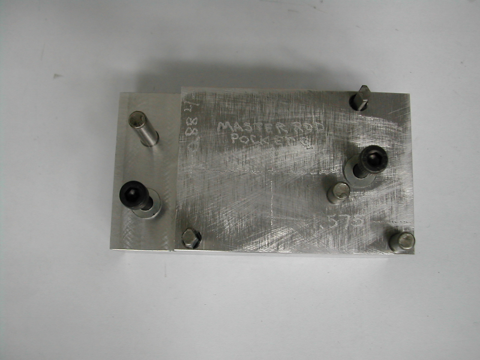
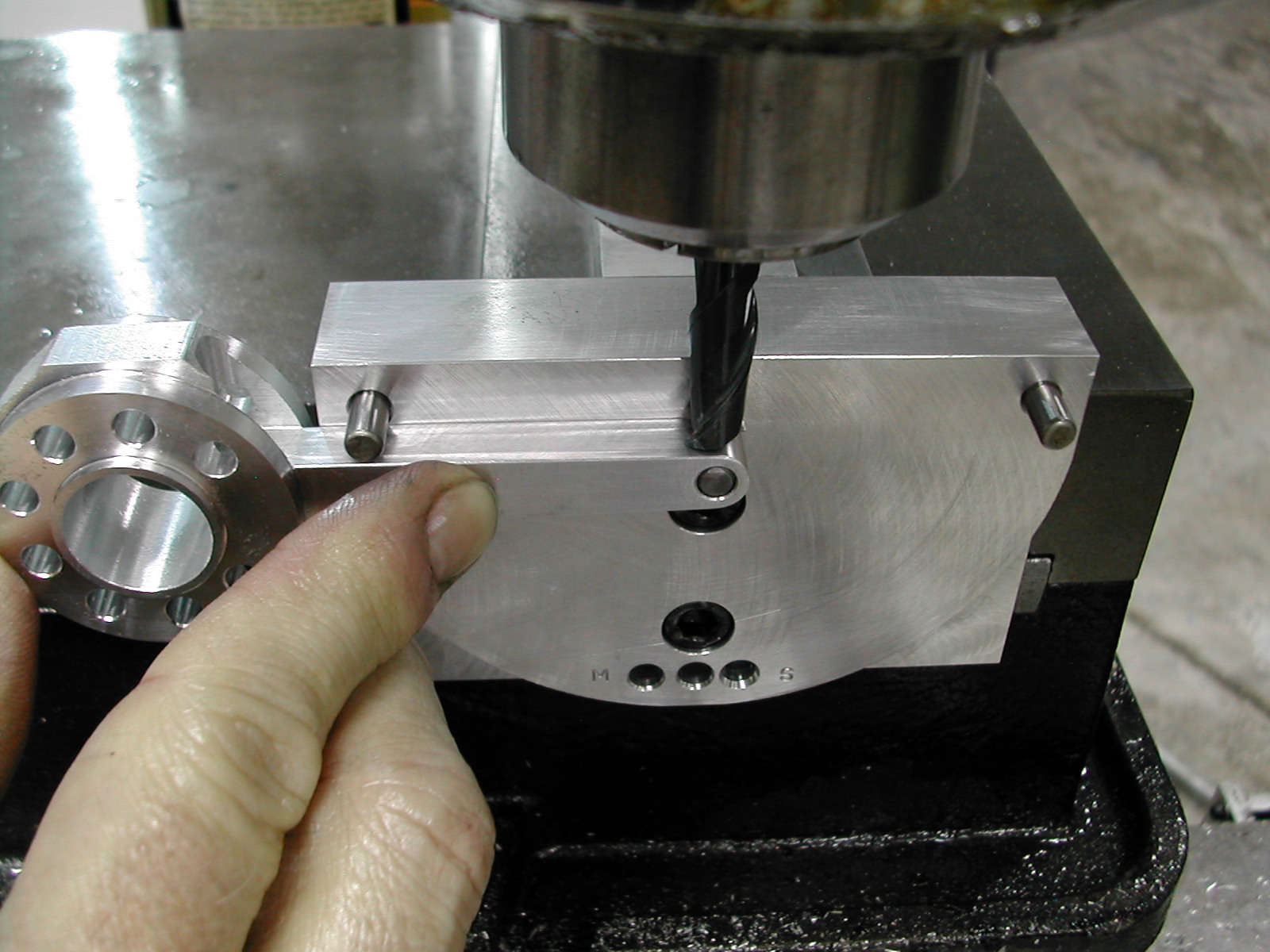
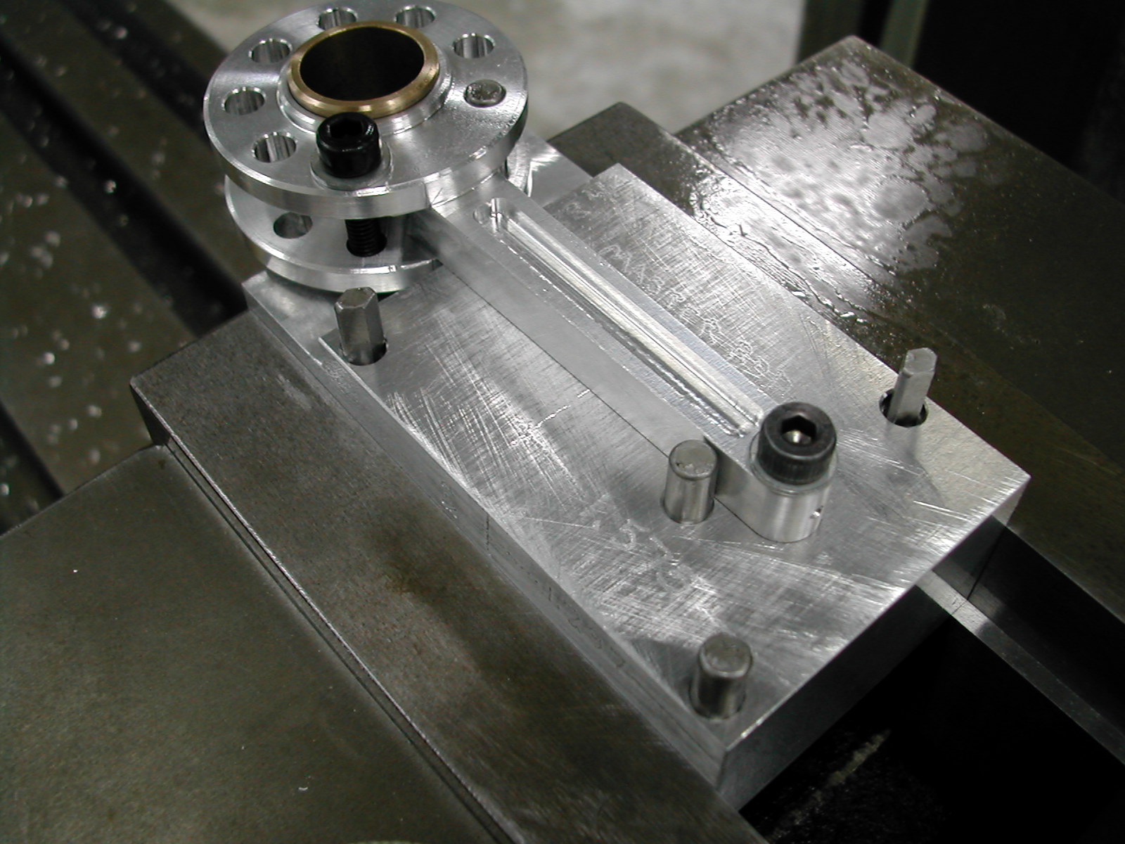
 This is how the master rod is mounted on the fixture for milling the side tapers. The rod is a slip fit over the locating pins and is clamped in place for machining by the vise jaws. If you use this fixture, you may need to change the width of the fixture to properly locate the part above the vise jaws.
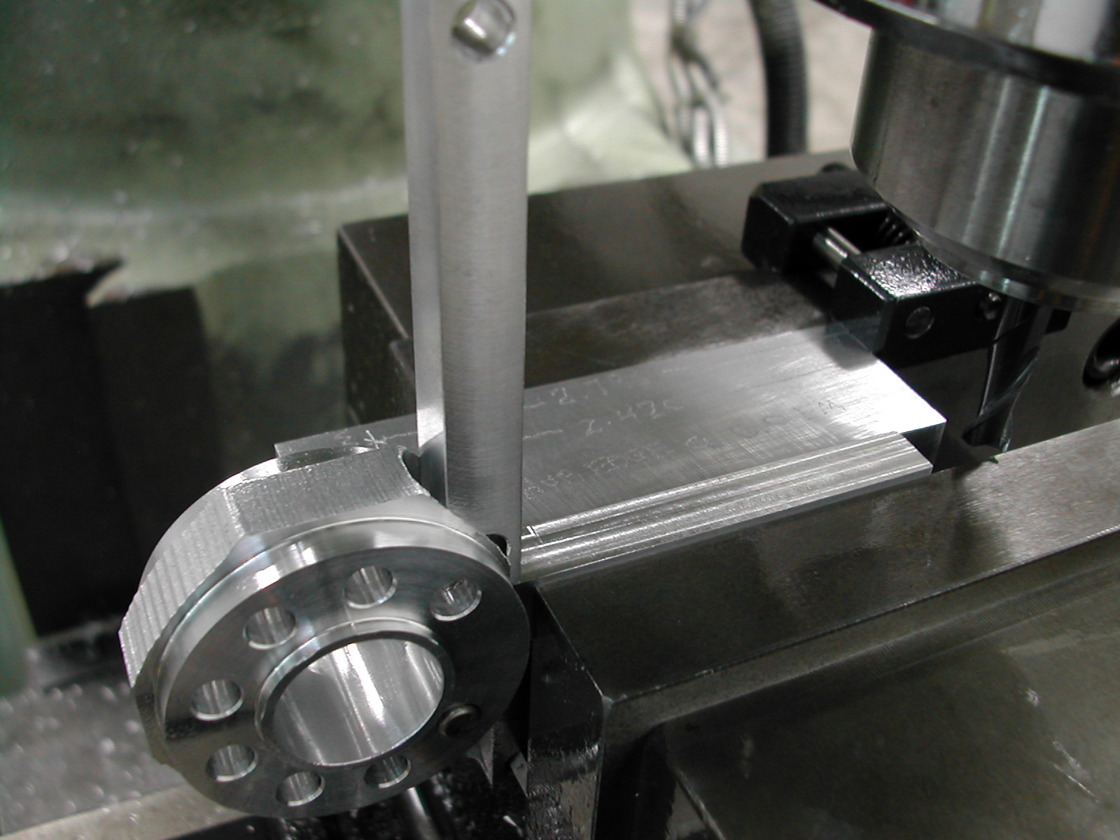
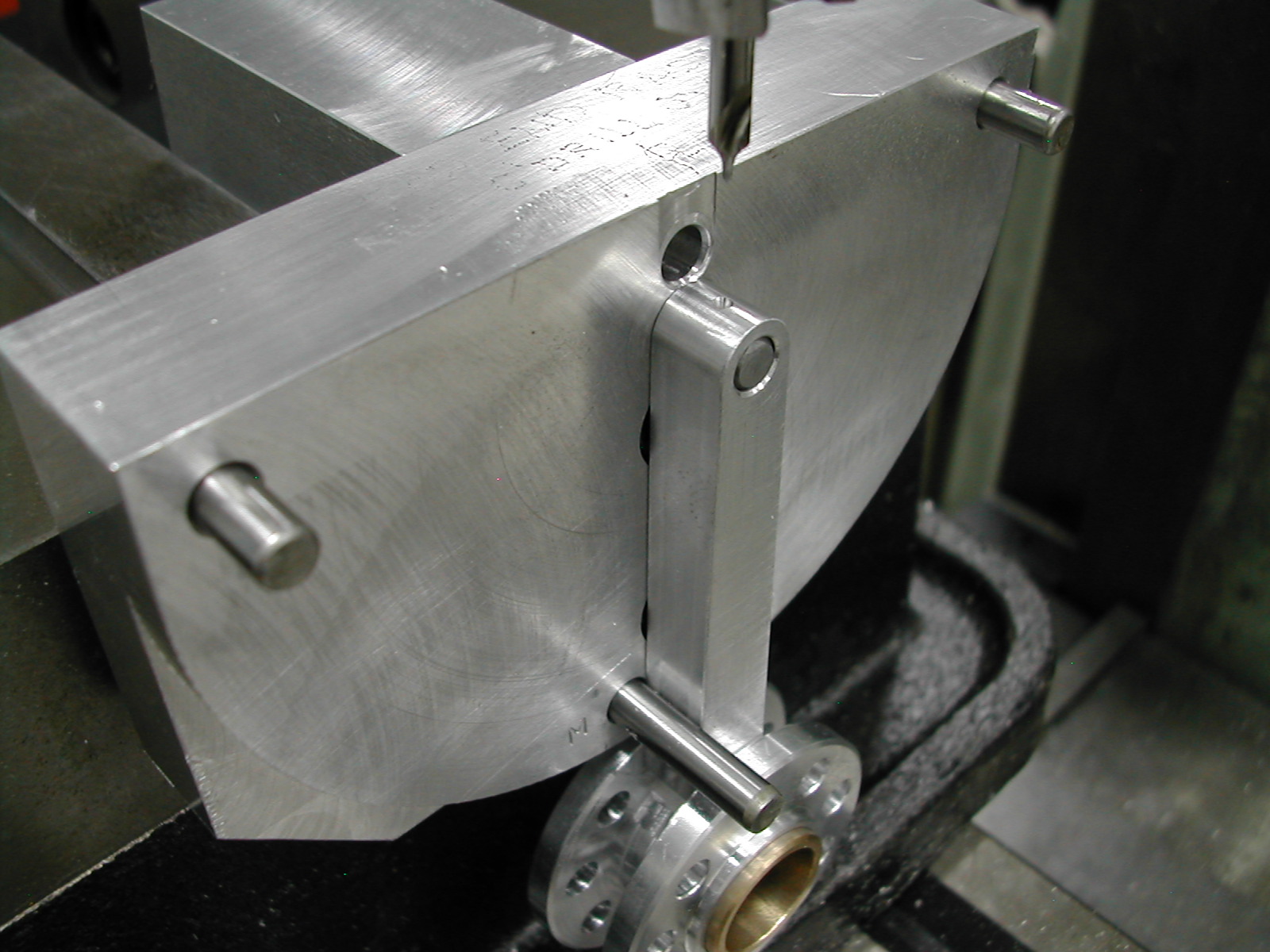
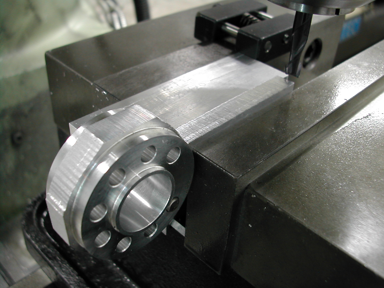 Here’s the master rod set up in the mill in preparation for milling the side tapers. I’ve used a vise stop to index the fixture so I can remove it to flip the rod over without having to re-do the setup.
 To determine the correct depth setting on the mill for the 0.312″ end width, a skim cut at the end of the rod is made on each side without changing the mill’s knee height.
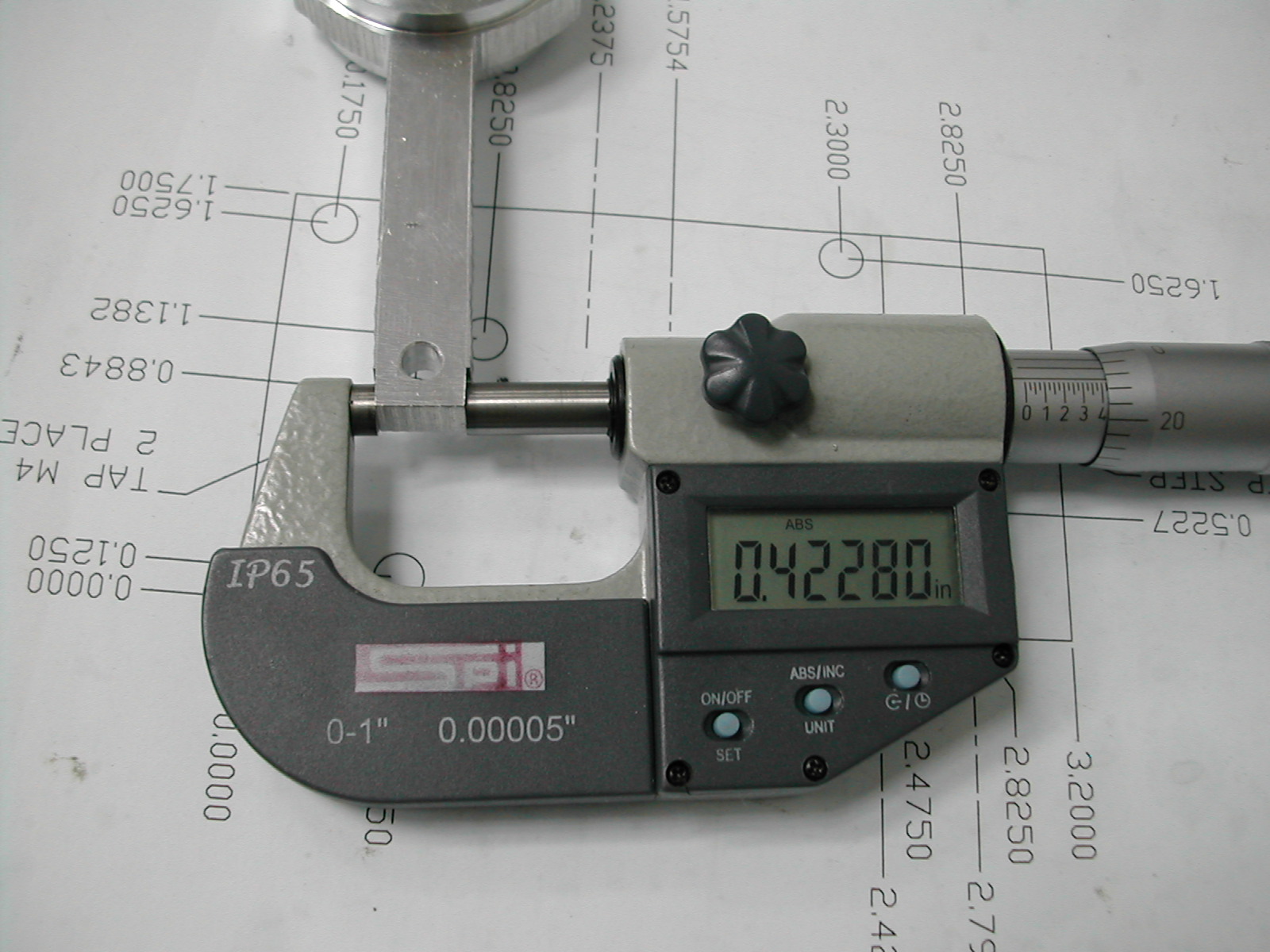 Because we are flipping the part about the part centerline in the fixture, the correct cutter depth is easily determined – just raise the knee half the difference of the measured reading from the desired 0.312″ dimension.
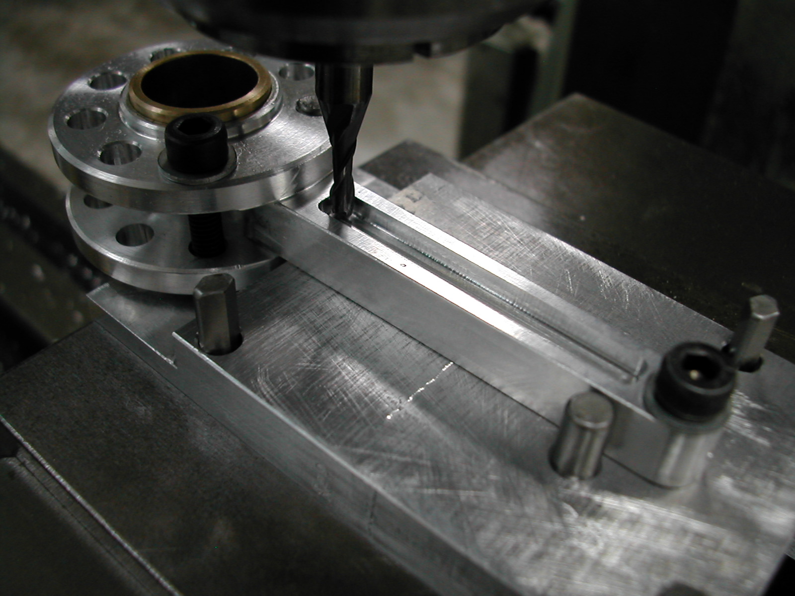
 Once you’ve determined the correct cutter depth, proceed to mill the side of the rod, and begin the pocket for the slave rods on each side of the master rod. One of the layers in the drawing above shows two critical endmill positions for the 6mm end mill I used.
The first is the tangent location of the intersection with the 1.500″ diameter, and the other is the maximum depth you can rough into the body without gouging the bottom surface of the finished pocket.
 Before changing the vise over to the rotary table to complete the master rod, I used my radiusing fixture to round the small end of the rod. See the slave rod write-up for a more detailed description of this process and for the drawing of the fixture.
 Next up was milling the slave rods pocket on the rotary table. The rotary table was mounted and then a stub arbor was milled in-situ to hold the rod for milling.
Once the arbor was mounted, the rotary table was locked on 0.0°, and the rod was leveled using a parallel and two pins in the slave rod holes while the SHCS was tightened to hold the rod in place.
 Next the center of the rod was located in Y by using an edge finder on the two slave rod pins.
 The final step was to locate the center of the part in X by using the edge finder on the two 1.500″ diameter bosses.
 Once the setup was done, the part was quickly roughed out with a 6mm end mill.
 The 6mm end mill was followed with a 3mm end mill to skim both sides to the final width, clean up the bottom to finished depth, and clean out both of the ends to the 0.060″ radius specified.
 The last step on the rotary table was to use a long center drill to chamfer the inside edges of the slave rod pocket. The outside edges will get a chamfer later when the bearing is installed.
 With the rotary table work finished, the vise is remounted and the radiusing fixture mentioned earlier is used to drill the oiling hole in the end of the rod.
 At this point, everything is done to the rod except for the side lightening pockets. I could have done this earlier, but I was waiting on a 4mm endmill with a corner radius and I didn’t want to hold up the rest of the work on the rod.
 Unfortunately, I waited just a little too long before milling the side pockets. Because I installed the bearing earlier, I ended up having to notch the fixture to clear the bushing where it extended past the rod. Once this was done, milling the pockets on both sides of the rod proceeded smoothly.
 And here’s the finished master rod needing only final deburring before it’s ready for use.
Disclaimer and License
All material, including the CAD drawings, relating to the construction of the Hodgson Radial presented on this site is free to use any way you see fit. However, no guarantees are made regarding the accuracy or correctness of the material presented here.
Links Used On This Page
(CAD drawings are in AutoCAD 2010 Format)