
- Hodgson Part 028/031, Sump Body & Cap
- Hodgson Part 029/030, Sump Oil Tubes
 If built according to the plans, the engine sump becomes a permanent part of the crankcase once the tubes are screwed into the crankcase and then silver soldered to the sump body. I know this has worked fine for many builders in the past, but I was uncomfortable doing this. What if the threaded connections leaked oil? What would happen if the sump were damaged? To avoid these and other potential problems with a permanently attached sump, I decided to make it removable.
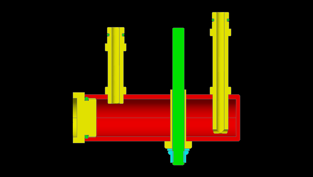
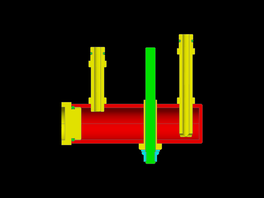 Here is the AutoCAD 2010 model of my 028/029 Sump Design. Both the crankcase to sump, and the sump to oil pump tube have been changed from threaded attachments to o-ring bosses. Since these oil tubes now slip into the crankcase, a method of retaining the sump onto the crankcase was needed. This was accomplished with a #10-32 threaded stud and nut. In addition, I added an o-ring seal to the sump cap as well.
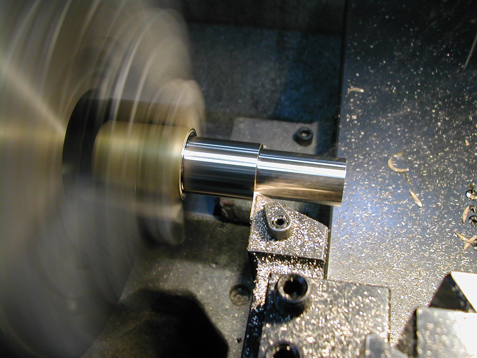 I started with a piece of 32mm brass about 100mm long. A piece of 25mm or 1″ would have resulted in less waste, but 32mm was all that was available. This piece will make both the body and the cap. I started by turning the body end down to the 0.750″ finish dimension and about 2.625″ long.
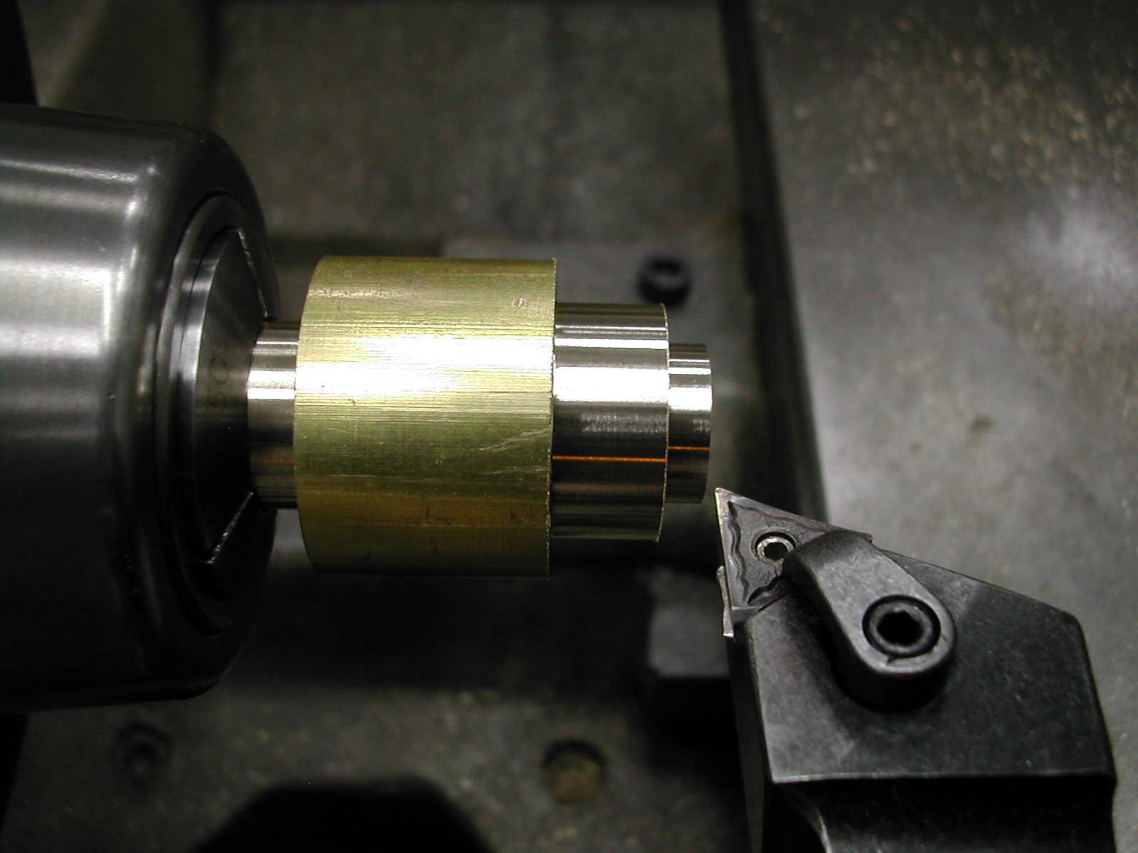
This is all that will be done on the sump body for a while. For now, this will give me a way to mount the part in a 5C collet so I can machine the cap on the other end of the stock. I’m machining the cap first so I can use it as a thread gauge for the body.
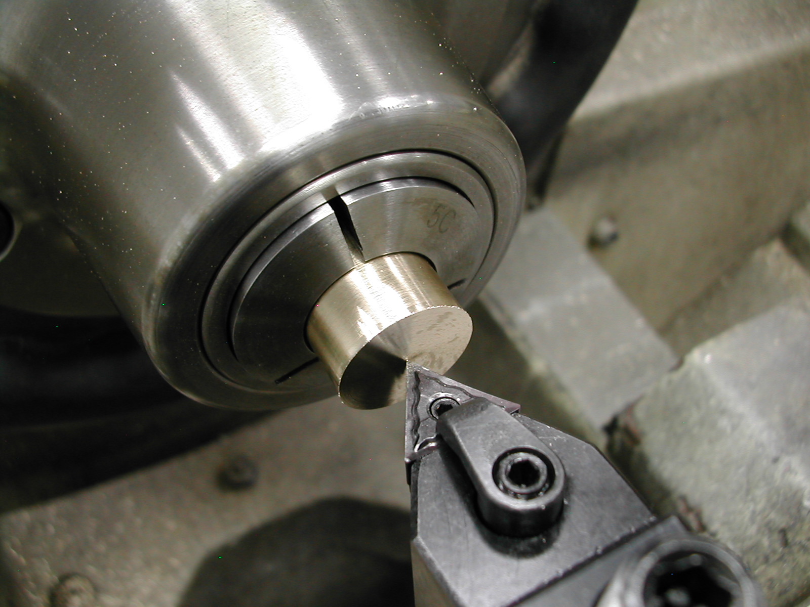
 With the 0.750″ end inserted into a 5C collet, I’ve started roughing out the cap end. I’m leaving about 0.005″ all over to remove with my grooving tool.
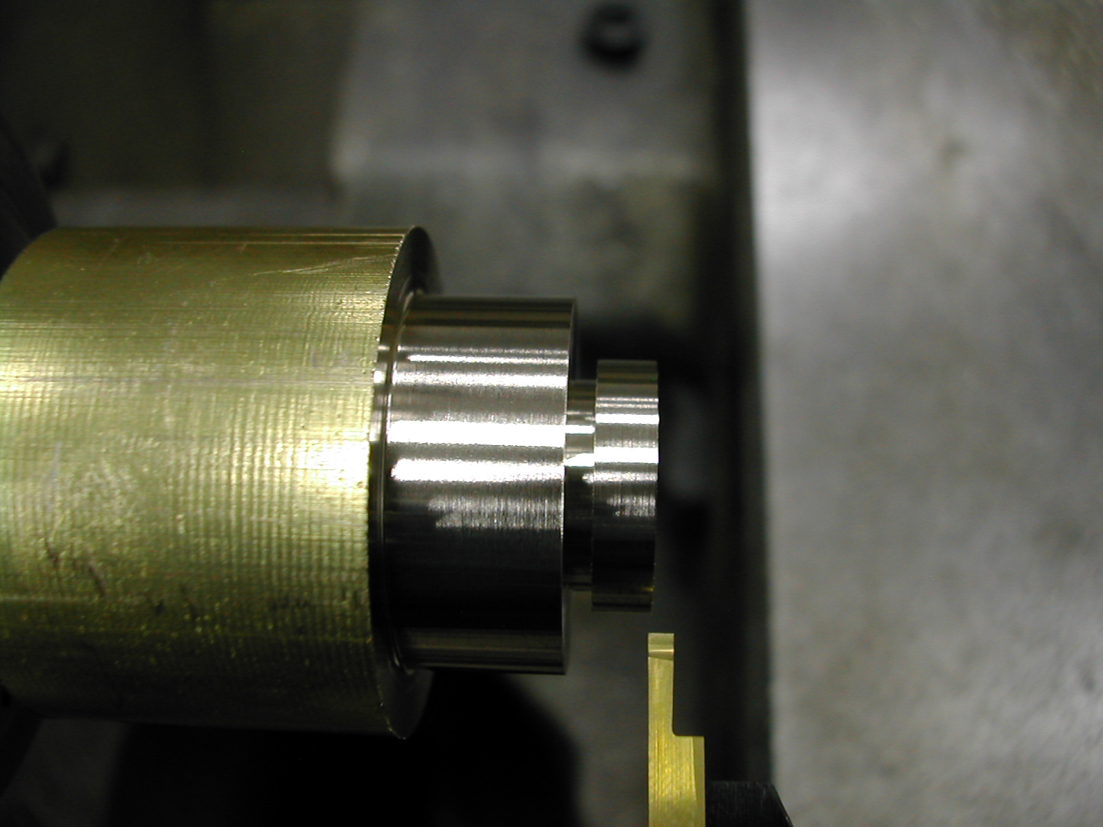 Here is the finish turning with the grooving tool. The o-ring groove for a 14mm I.D. x 1.5mm thick o-ring does double duty as a thread relief groove.
 The cheap lathe I have available in China will split threads even if I engage exactly the same number on the half-nuts. So once I start threading, I have to leave them engaged until I finish. That means I have to “thread” my way back to the starting point each pass.
Because of that, I like to thread away from the shoulder which means I need to thread from left to right and therefore run the lathe in reverse. So, I’m going to use a left-hand threading tool mounted upside down in the tool holder.
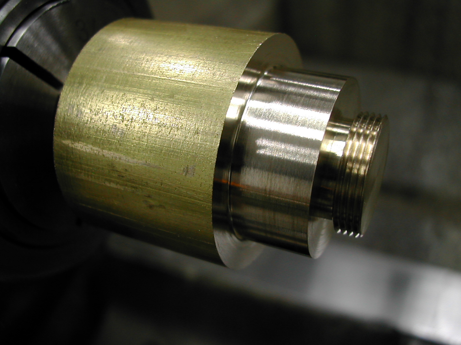 With the threads finished, it’s time to head to the mill to cut the hex.
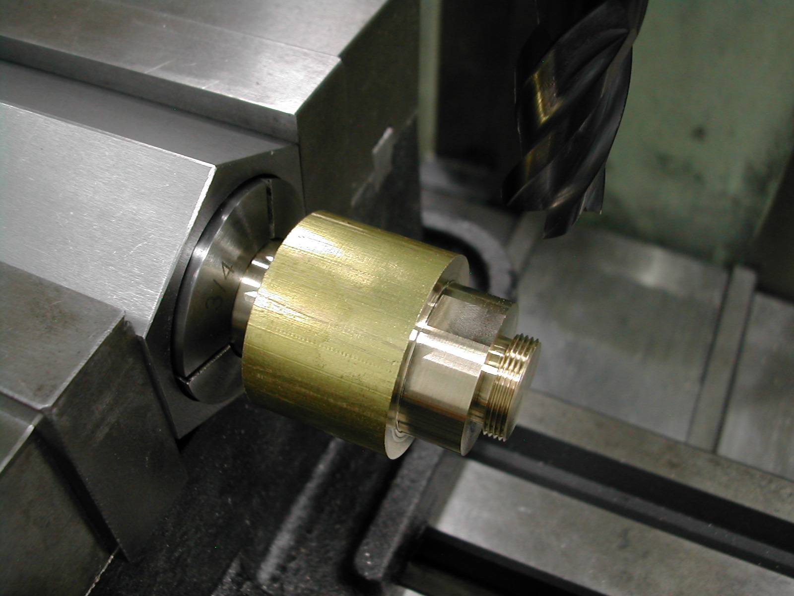 I’ve transferred the 5C collet and stock to a hex collet block clamped in the mill vise and I’ve made a test cut on two opposite sides of the hex. I’ll measure across these flats, subtract that from the 13/16″ final dimension and raise the mill’s knee one-half the difference.
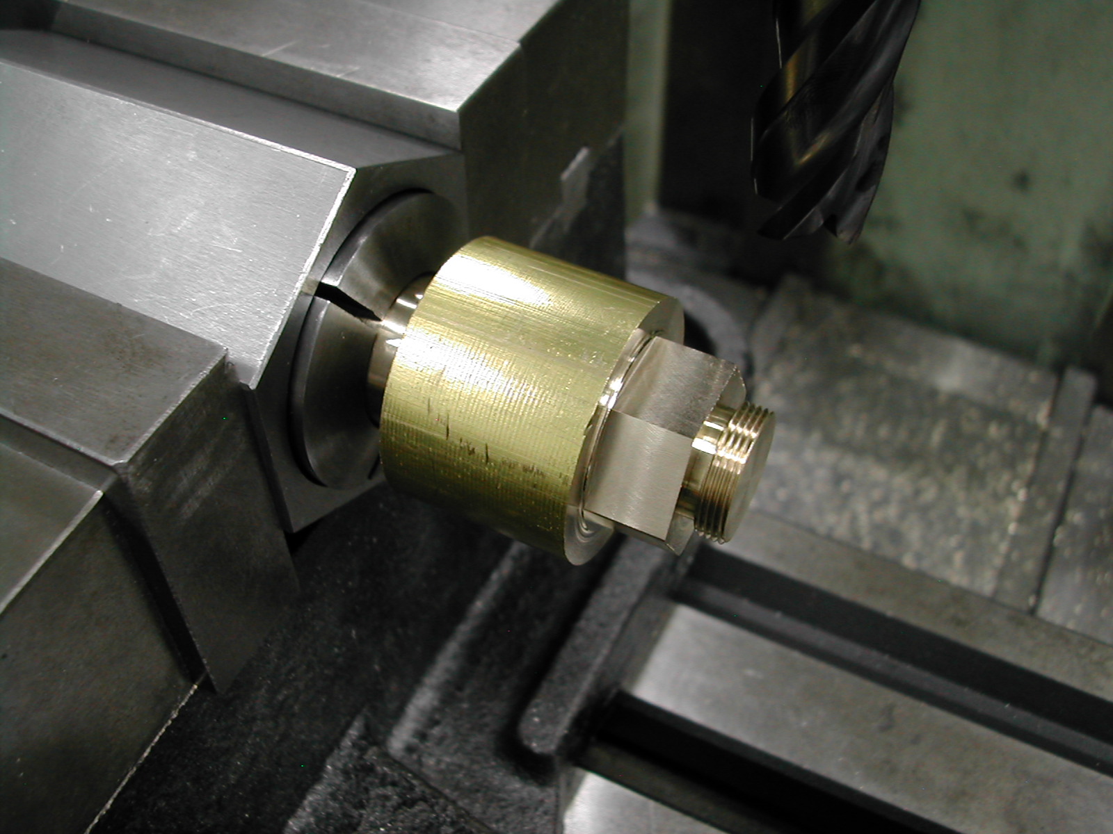 I’ll deburr the hex with a 600-grit abrasive file before moving back to the lathe to finish the cap.
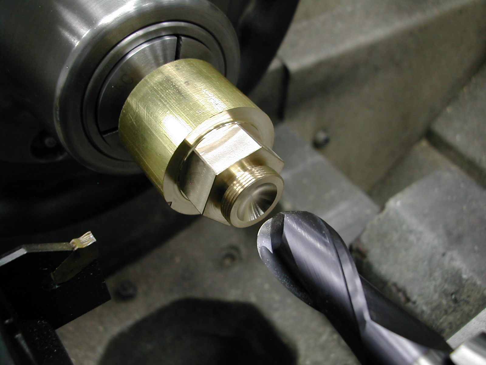 Before parting the cap off, I decided to add a little embellishment on the inside end with a 3/4″ ball-nose endmill. No one will ever see it, but I’ll know it’s there.
 The cap is now parted off from the stock and set aside to finish the outside surface later.
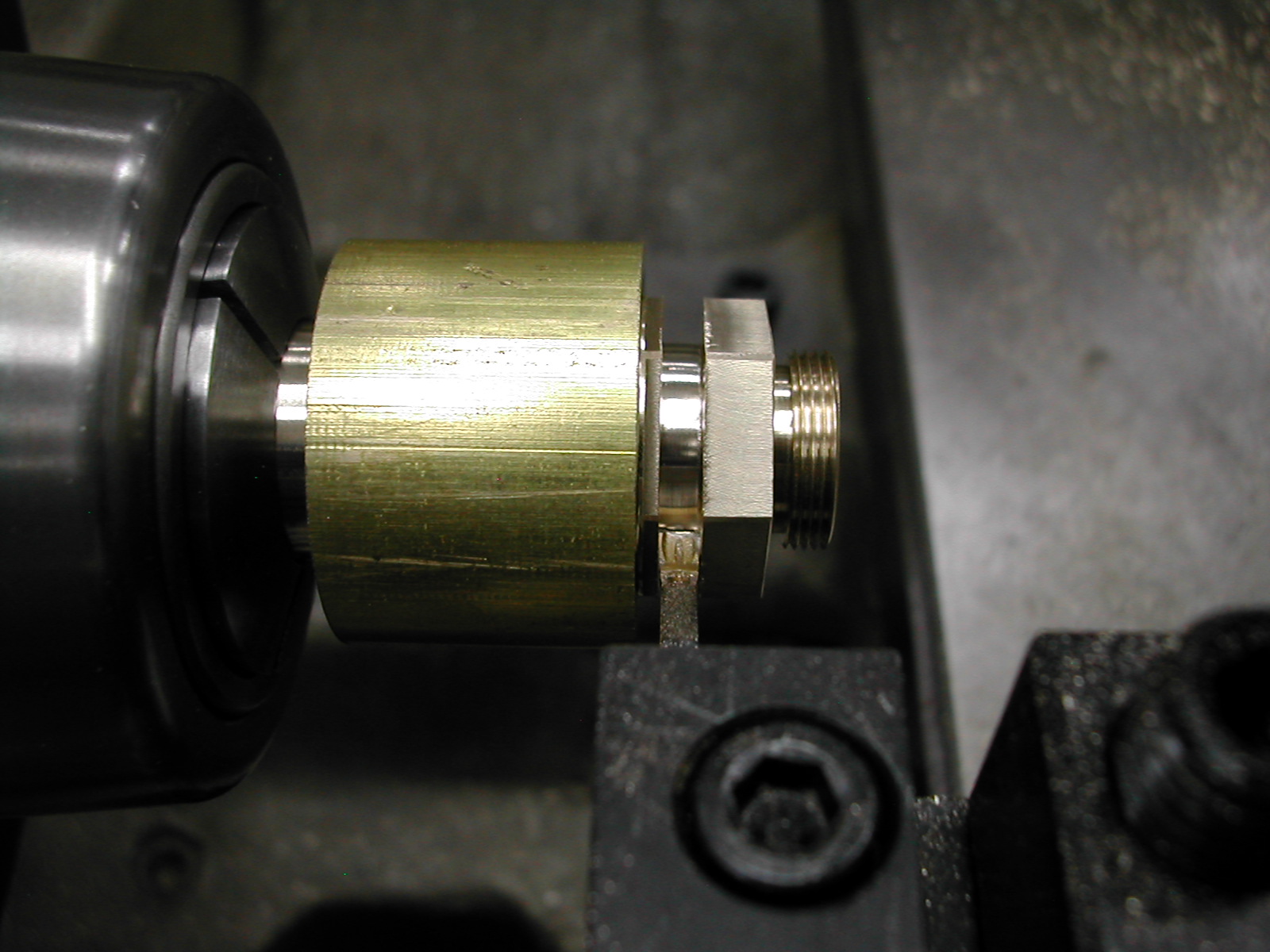
 The excess stock is parted off from the sump body which is inside the 5C collet.
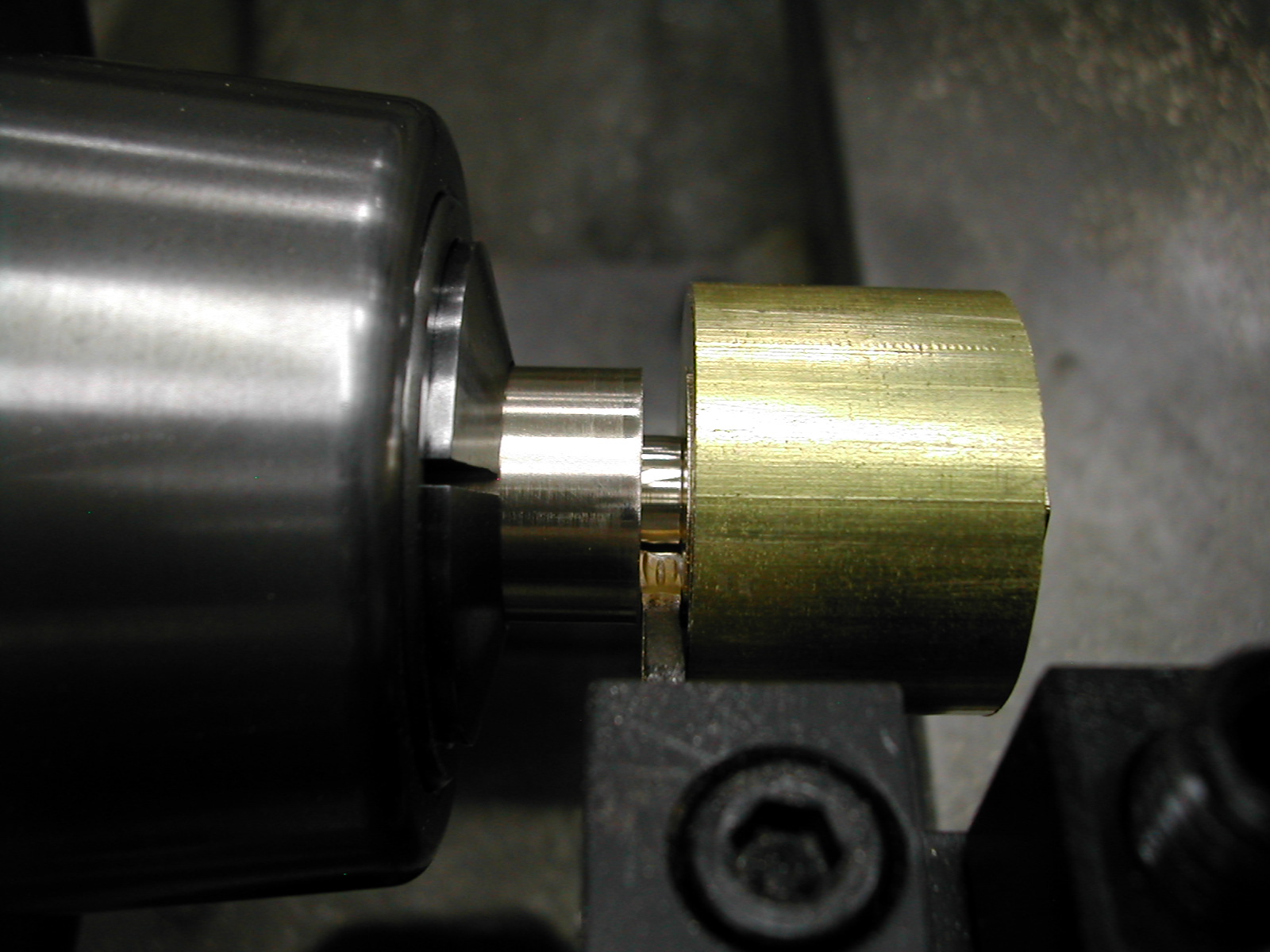
 And the sump body is faced to length.
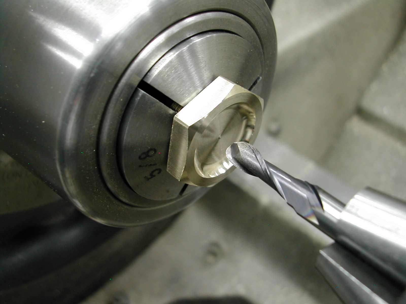
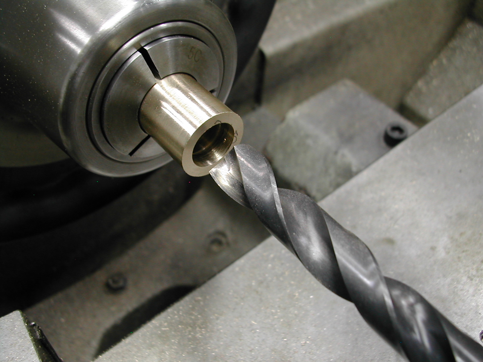 A 1/2″ drill clears out most of the body.
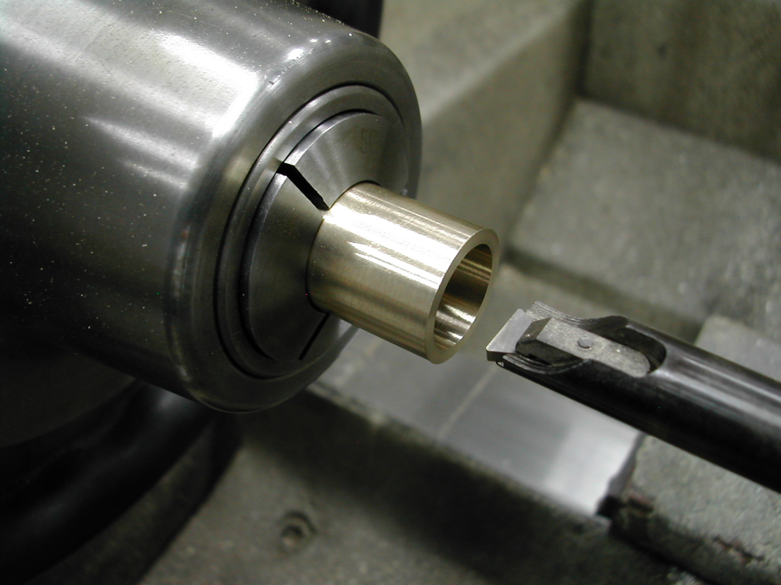 Followed by boring to get the final diameter and a flat bottom hole. The plans call for a 0.600″ bore, but 0.595″ is a better minor thread diameter for a 5/8-32 thread.
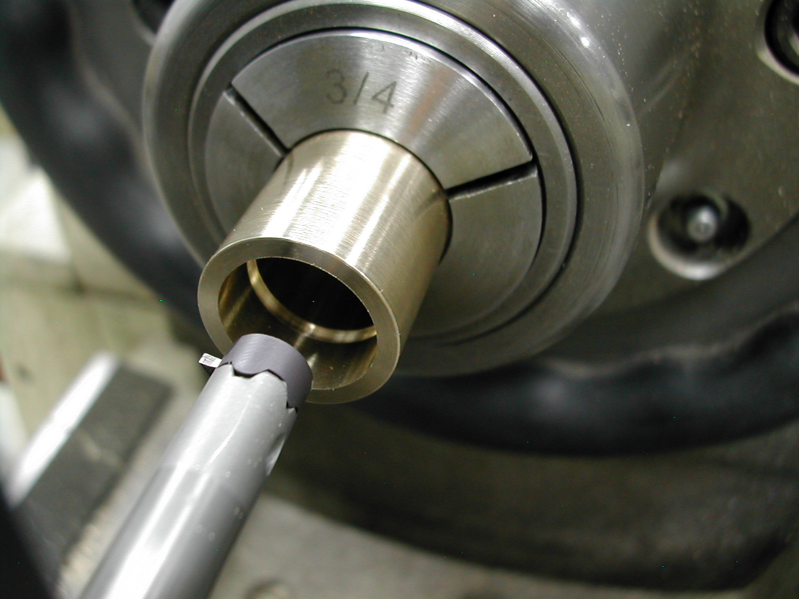 I added a 0.070″ thread relief groove behind the 0.250″ length called out in the plans. There was sufficient room for this without interfering with the hole for the forward oil tube.
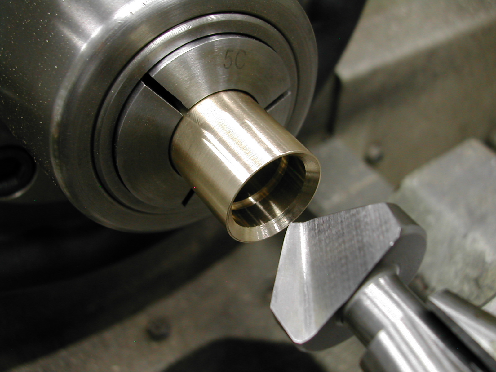 A 90° countersink makes quick work of the chamfer for the o-ring seat.
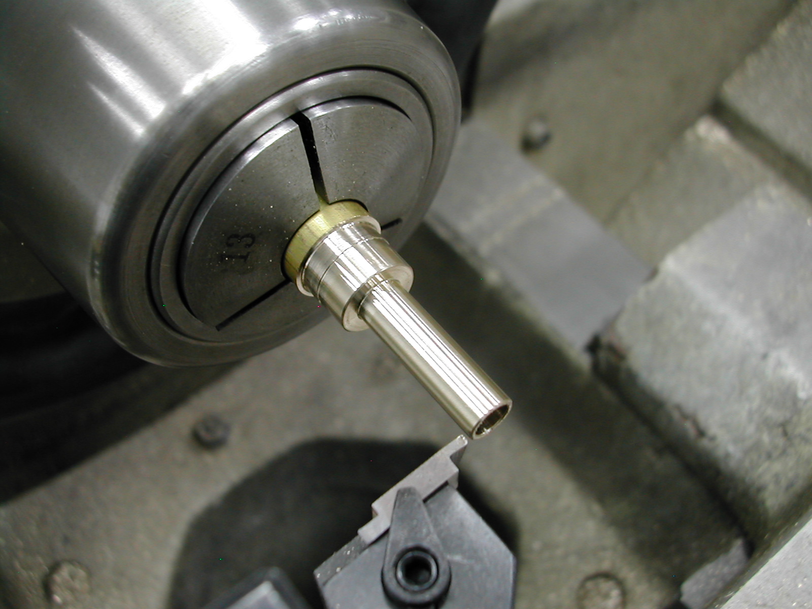
 I didn’t have a left-hand internal threading tool, so I had to run this thread from right to left working blind inside the sump body.
 With the lathe work completed on the sump body, the cap was chucked up in a 5/8″ collet and faced to length. A 4mm ball-nose endmill was used to add the embellishment on the outside face. I like the look of the radius better than a sharp corner here.
 The modified sump body needs a sleeve where the clamping stud passes through it. For now, I’ve reamed the hole to 0.1885″ for fixturing on the brazing jig. I’ll open it up with a #10 reamer after the assembly is brazed.
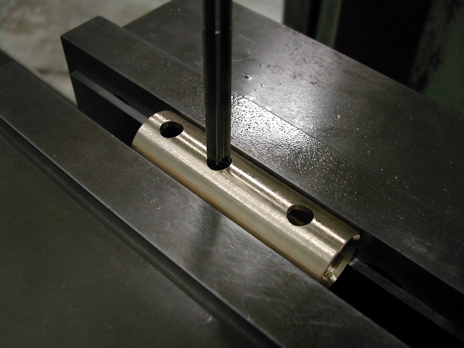 It’s now back to the mill to add the holes for the oil tubes and sleeve for the clamp stud. These were drilled and reamed to 0.251″. The additional hole for the clamp stud sleeve which I’m reaming here, goes all the way through the sump body.
If you’re particular about details as I am, be sure to screw the cap onto the body so you can orient these holes so the hex on the cap is aligned with either a flat or point vertically depending on your preference.
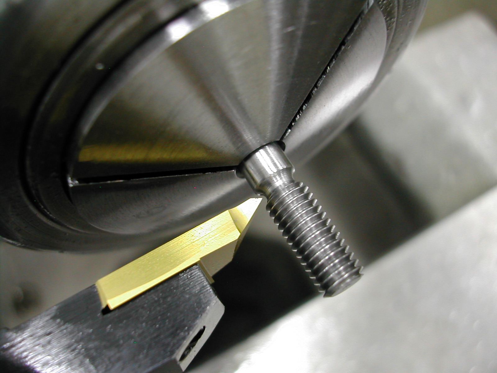
 The last piece on my modifed sump is the stud that holds the o-ringed sump onto the crankcase. This is a piece of 3/16 stainless shafting and the first step to prepare for adding #10-32 threads at each end is to provide a thread undercut.
I’m using a 1mm radius insert and plunging to the minor diameter. I did this on both ends of the stud before moving on to threading.
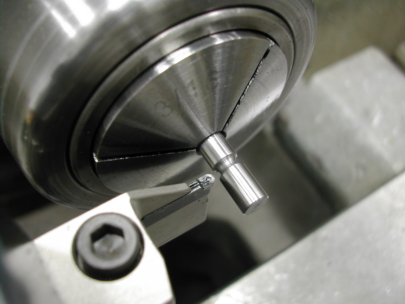
 The sump end of the stud is finished and is verified with a #10-32 UNF-2A thread gage.
Both ends of the stud are now threaded and the part is ready to be installed on the crankcase.
Disclaimer and License
All material, including the CAD drawings, relating to the construction of the Hodgson Radial presented on this site is free to use any way you see fit. However, no guarantees are made regarding the accuracy or correctness of the material presented here.
Links Used On This Page
(CAD drawings are in AutoCAD 2010 Format)