
- Hodgson Part 073, Header Flange
- Hodgson Part 074, Intake Crankcase Mount
- Hodgson Part 075, Flange Gasket
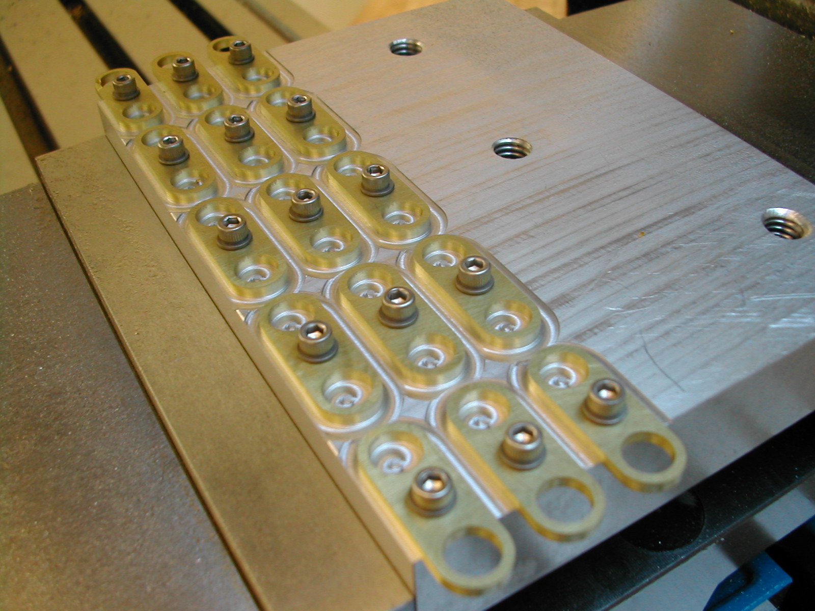
I clamped up a scrap tooling plate in the mill vise and used a couple of small clamps to hold a 3/32″ sheet of yellow brass on it. I then laid out a 1.375″x0.600″ grid of 15 flanges, drilling a clearance 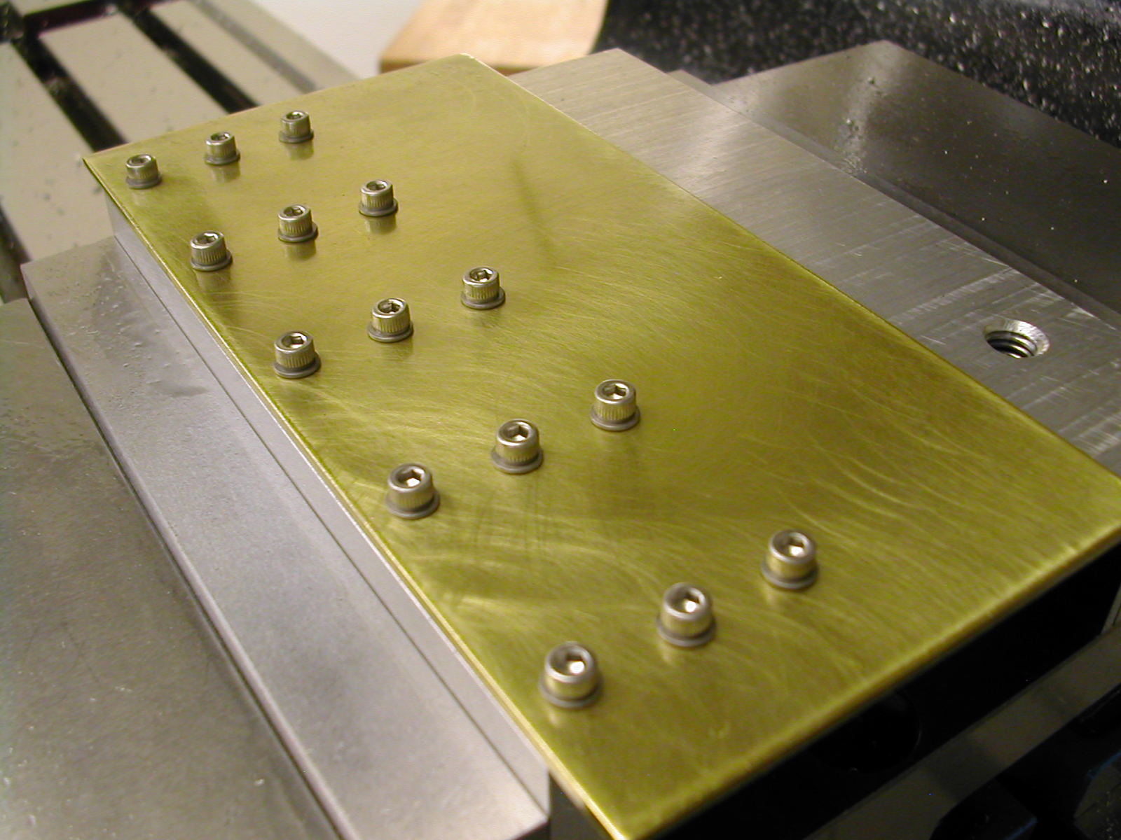 hole in the brass, and tapping the tooling plate below with a #6-32 tap. Once some #6 screws were tightened down, I was ready to roll.
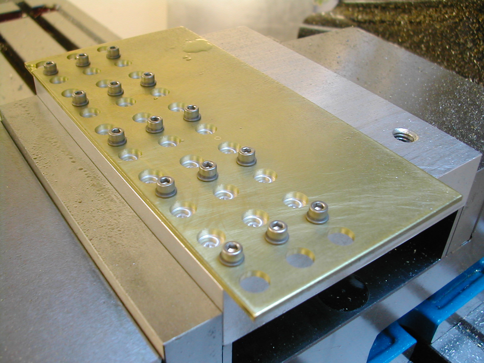 The brass tubing I’ll be using to make the intake and exhaust pipes runs between 0.310″ and 0.312″ so the first cuts were the 0.314″ holes for the pipes. You don’t want to make these too tight a fit as you need some room for a good solder bond. As you can see in the upper left hand corner, it’s always good to make a few extra.
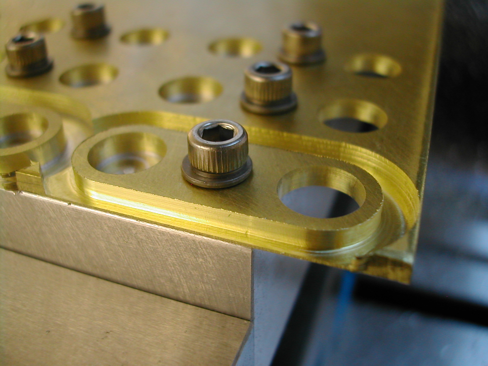 With the holes cut, I proceeded to profile the outside of each flange. Since these flanges are only held by a single central screw, a simple trick reduces the tendency for them to move during cutting.
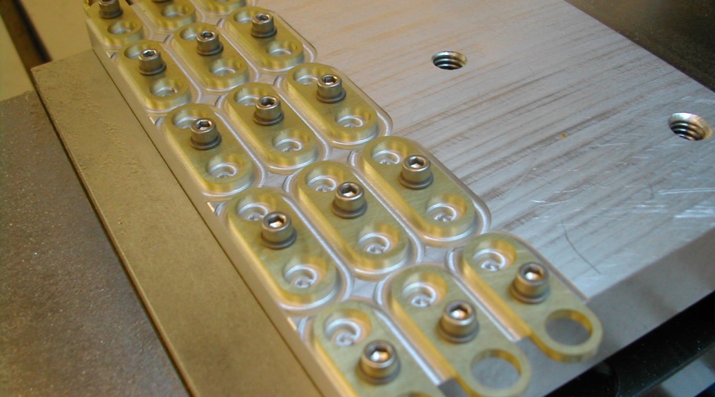
I cut them down in 0.042″ steps leaving a pass of only 0.010″ a the cut that releases the flange from the stock. This thin web still securely holds the flange during the 0.042″ cut that creates it, but itself produces very low cutting forces on the final depth cut. After the part is free a final finish cut of 0.005″ is run around the perimeter – also with very low cutting forces.
 All the profiling done with the excess stock removed. All of the flanges remained securely held by the single screw.
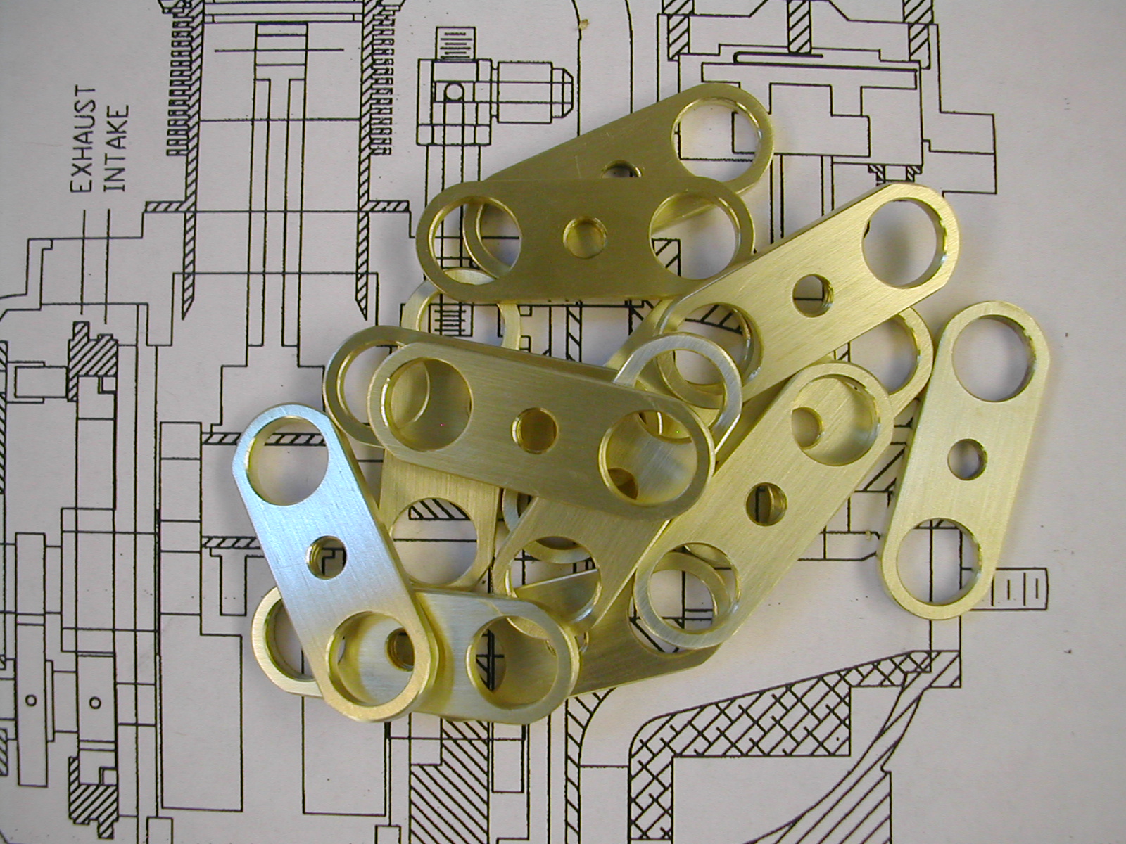 Deburred and ready to be silver soldered to the intake and exhaust pipes.
Disclaimer and License
All material, including the CAD drawings, relating to the construction of the Hodgson Radial presented on this site is free to use any way you see fit. However, no guarantees are made regarding the accuracy or correctness of the material presented here.