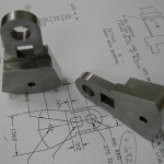
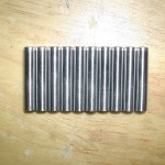
 For the full floating wrist pins, I started with some 12L14 unhardened precision ground shafting from McMaster-Carr. This shafting, p/n 1327k52, has a diametrical tolerance of +0.0000″ to -0.0002″ with a 10rms surface finish. The aluminum rivets used for the buttons were also purchased from McMaster (p/n 94439A330).
Monthly Archives: February 2014
Hodgson Part 050, Pistons
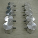 For my pistons, I chose to use silicon/nickel aluminum, alloy 4032-T6 because of it’s high wear resistance. This material is commonly used for brake master cylinders and forged pistons. I was able to purchase some 26mm diameter material, which worked out just fine for the 1.000″ finished O.D. of the pistons.
Hodgson Part 048, Slave Rod Pins
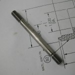
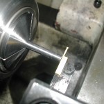 Finally, a nice simple part if you ignore the 0.018″ snap ring grooves. I started with some 12L14 unhardened precision ground shafting from McMaster-Carr. This shafting, p/n 1327k52, has a diametrical tolerance of +0.0000″ to -0.0002″ with a 10rms surface finish.
Hodgson Part 047, Slave Rods
The slave rods were made from a piece of aluminum 7075-T651 sawn from plate.
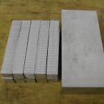 Here’s the material sawn up for the master rod and the slave rods. Everything was sawn about 0.1″ oversize in all dimensions to all for clean up.
Hodgson Part 046, Main Rod Bearing
The main rod bearing was a purchased SAE660 bronze sleeve bearing p/n 6381K528 available from McMaster-Carr. It has the correct I.D., but the O.D. is larger and the length is a little long as well.
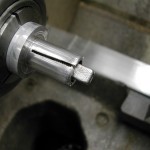 First step is to make a little 9/16″ expansion arbor to hold the bushing for machining. This was a scrap piece of aluminum tapped with a 1/8″ pipe thread and then split with a hacksaw while still chucked in the collet.
Hodgson Part 045, Master Rod
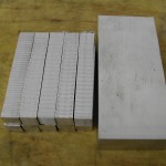 The master rod was made from a piece of aluminum 7075-T651 sawn from plate.
One master rod and ten slave rod blanks ready for squaring.
Hodgson Part 043, Impeller
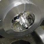 The impeller started life as a 125mm diameter by 300mm piece of Aluminum 7075-T6. I bought a stick of this long enough to make the front cover, crankcase, rear seal plate, air guide, impeller, and a few fixtures. The diameter was needed to accommodate the crankcase so I did end up wasting a little material on the other parts.
Hodgson Part 035, Crank Cheeks
Hodgson Part 029/030, Sump Oil Tubes
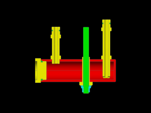 As explained in the construction log for the sump body, I’ve modified the sump tubes to slip into the crankcase instead of attaching with threads.
Hodgson Part 028/031, Sump Body & Cap
 If built according to the plans, the engine sump becomes a permanent part of the crankcase once the tubes are screwed into the crankcase and then silver soldered to the sump body. I know this has worked fine for many builders in the past, but I was uncomfortable doing this. What if the threaded connections leaked oil? What would happen if the sump were damaged? To avoid these and other potential problems with a permanently attached sump, I decided to make it removable.

