
- Hodgson Part 050, Pistons
- Hodgson Part 051/052, Wrist Pins & Buttons
 For my pistons, I chose to use silicon/nickel aluminum, alloy 4032-T6 because of it’s high wear resistance. This material is commonly used for brake master cylinders and forged pistons. I was able to purchase some 26mm diameter material, which worked out just fine for the 1.000″ finished O.D. of the pistons.
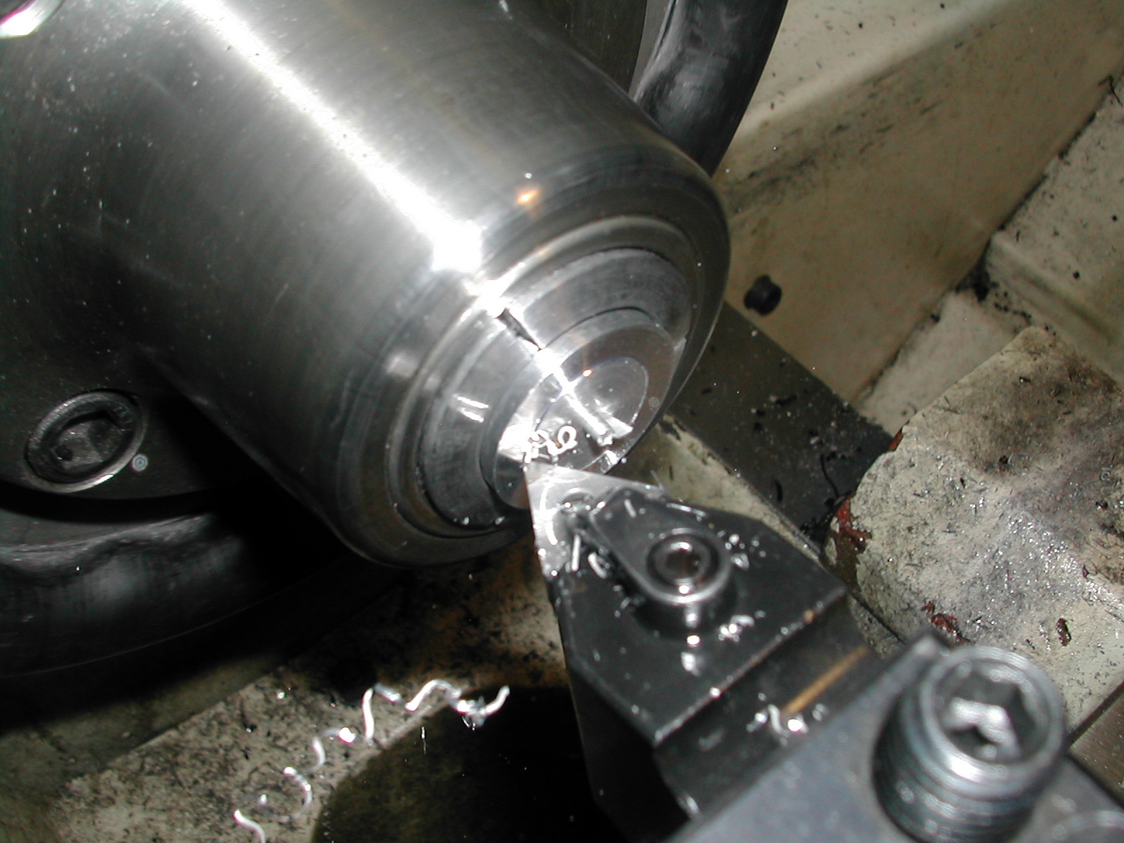
 To start off, I’m using my facing tool as a part stop. Once the chuck is tightened, the part is faced off.
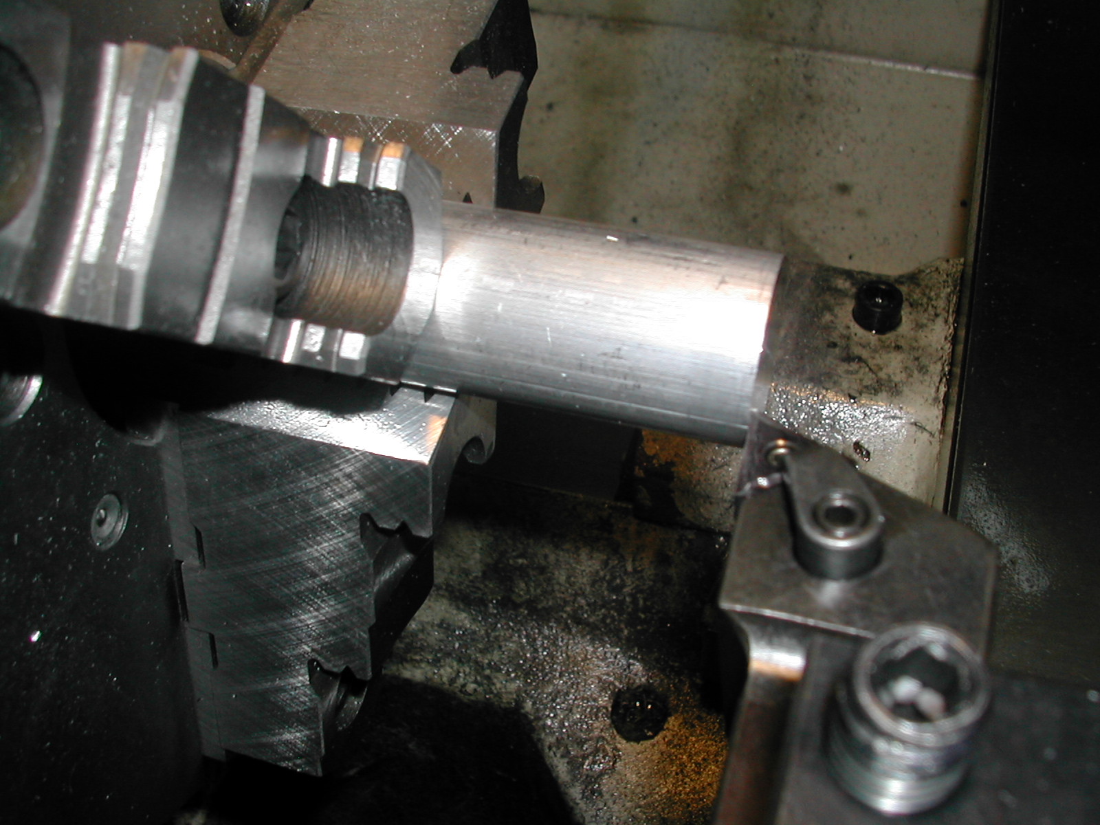
 Here I’m roughing the piston O.D. with the same tool I face with.
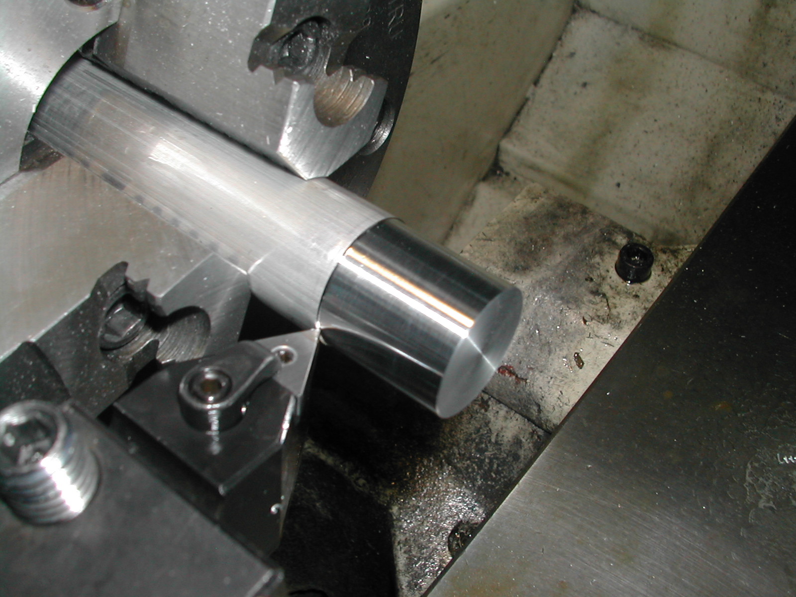 Finish turning the final 0.005″ off the diameter with a high spindle speed and slow feed allowed me to keep the finished O.D. between 0.9975″ and 0.9970″ on all the pistons.
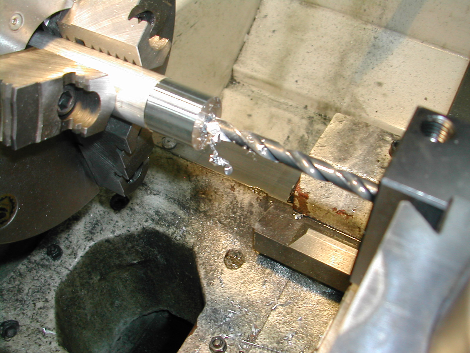 After center drilling, I’m roughing out the rod pocket with a 5/16″ drill mounted on the toolpost so I can accurately control the depth.
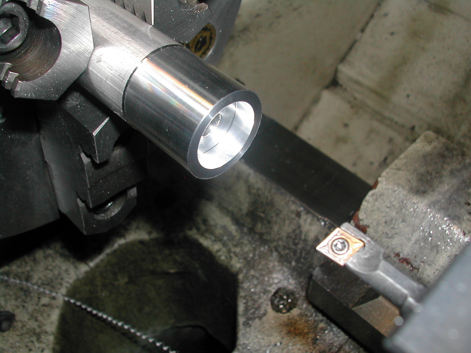 The next step is to add the skirt recess with a small boring bar. I tried to hold this diameter fairly close because I would be using it later to locate the piston for drilling the wrist pin hole and the oil drain holes.
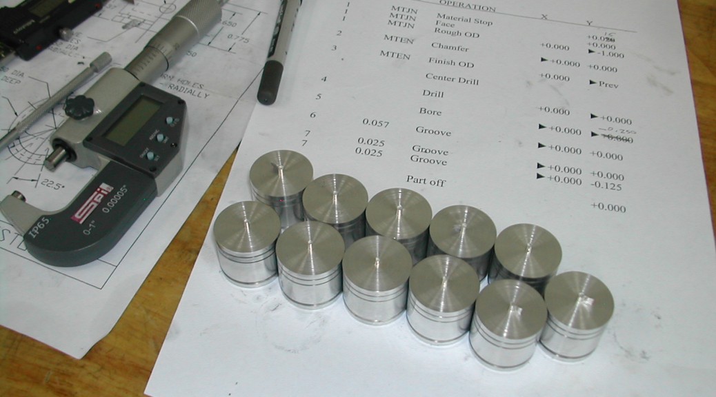
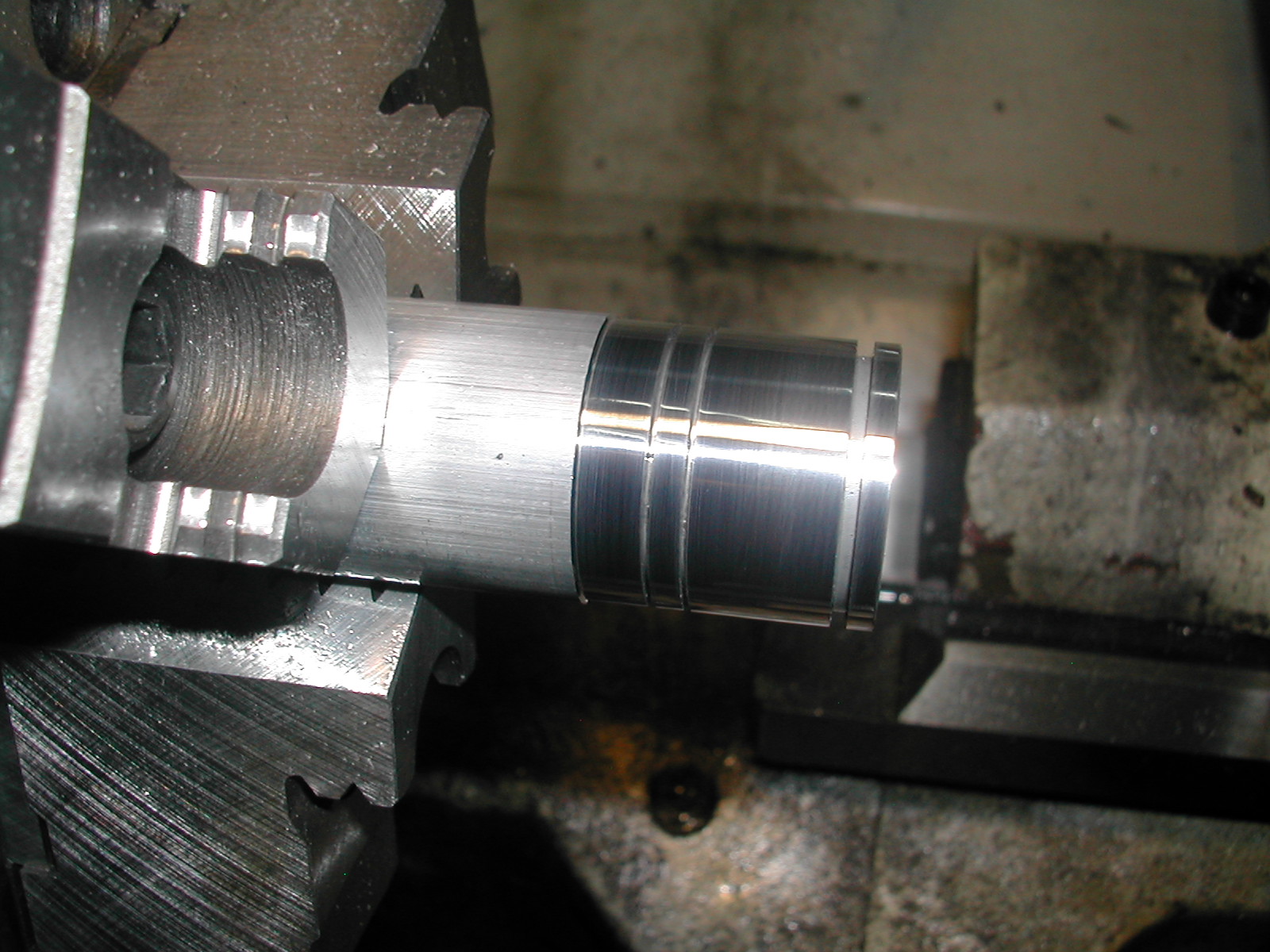
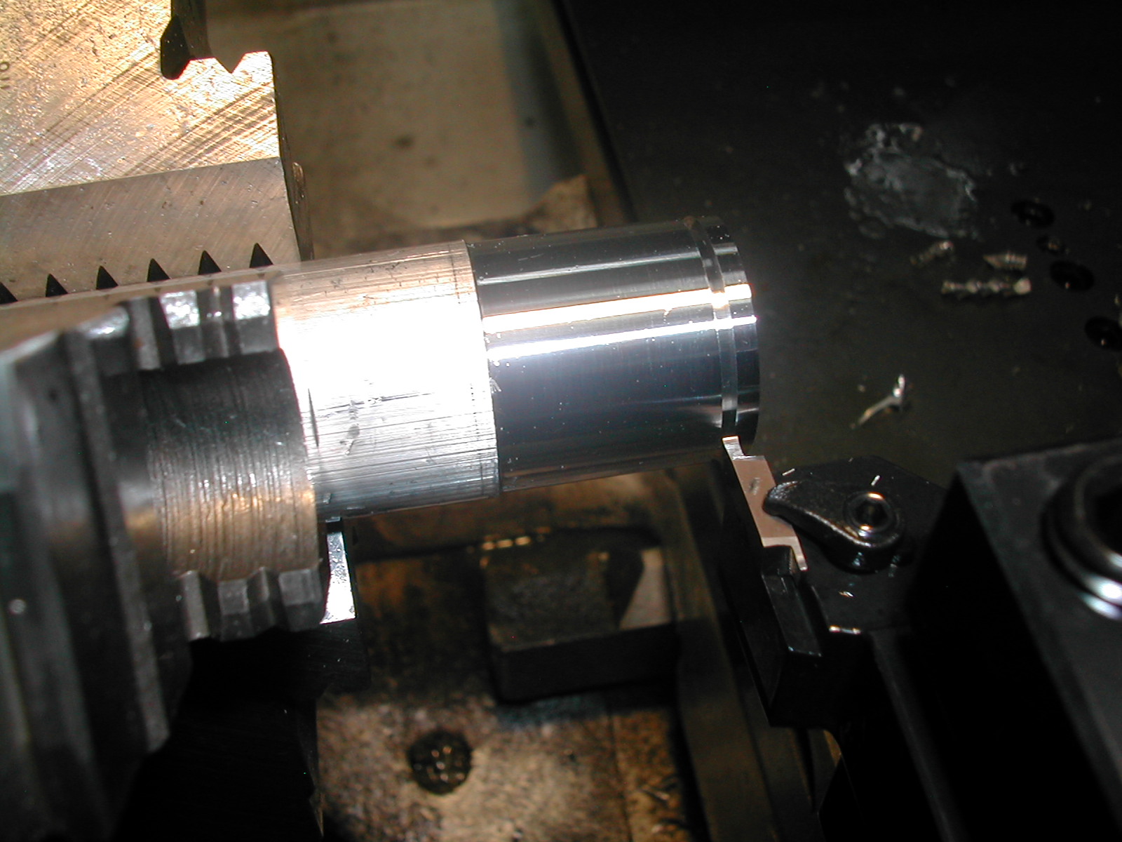 Now for the oil ring groove. There are conflicting dimension on the plans for the ring groove depths. Two call outs say the ring grooves are 0.055″ deep, while another shows the bottom of the groove to be 0.900″ diameter. I went with the 0.055″ dimension as the extra depth would not adversely affect performance, but would make putting the rings on much easier.
 The two compression ring grooves are added in the same manner as the oil ring groove.
 After the grooves were cut, I knocked down any burrs with some 1200 grit paper backed by a steel rule.
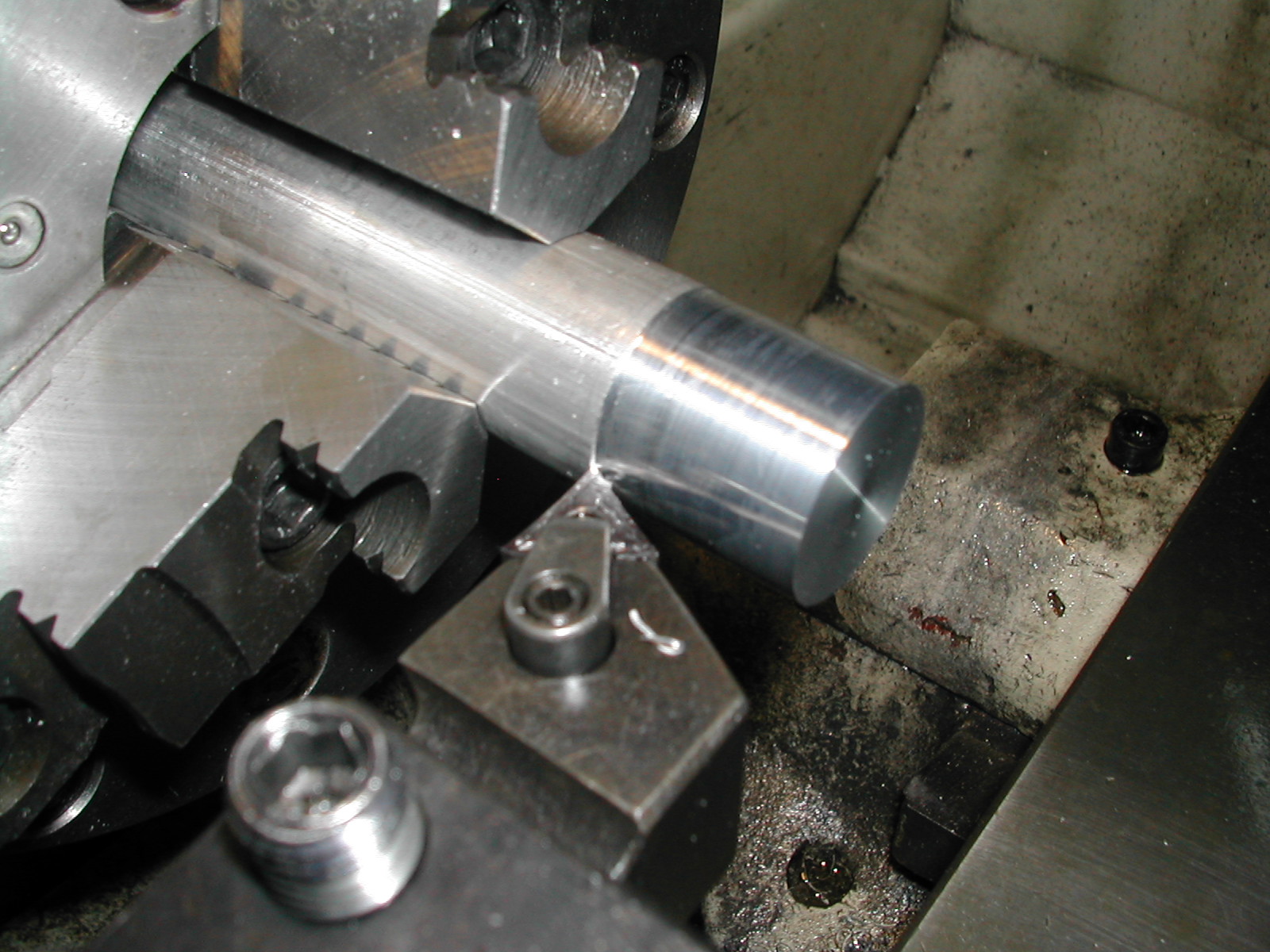
 The piston blanks are parted off about 0.030″ long with a 3mm parting blade.
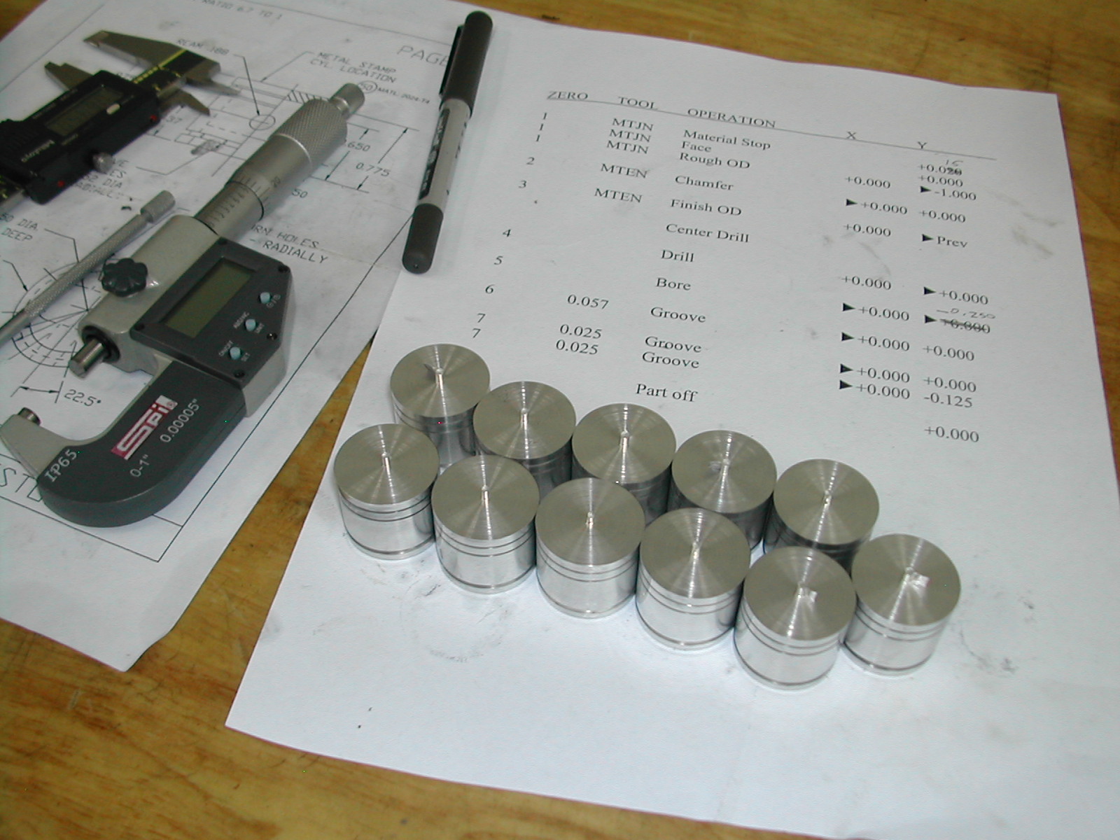 I repeated the above steps to make a total of 11 piston blanks. I wanted one extra for setup as well as an additional one to make a cut-away display later.
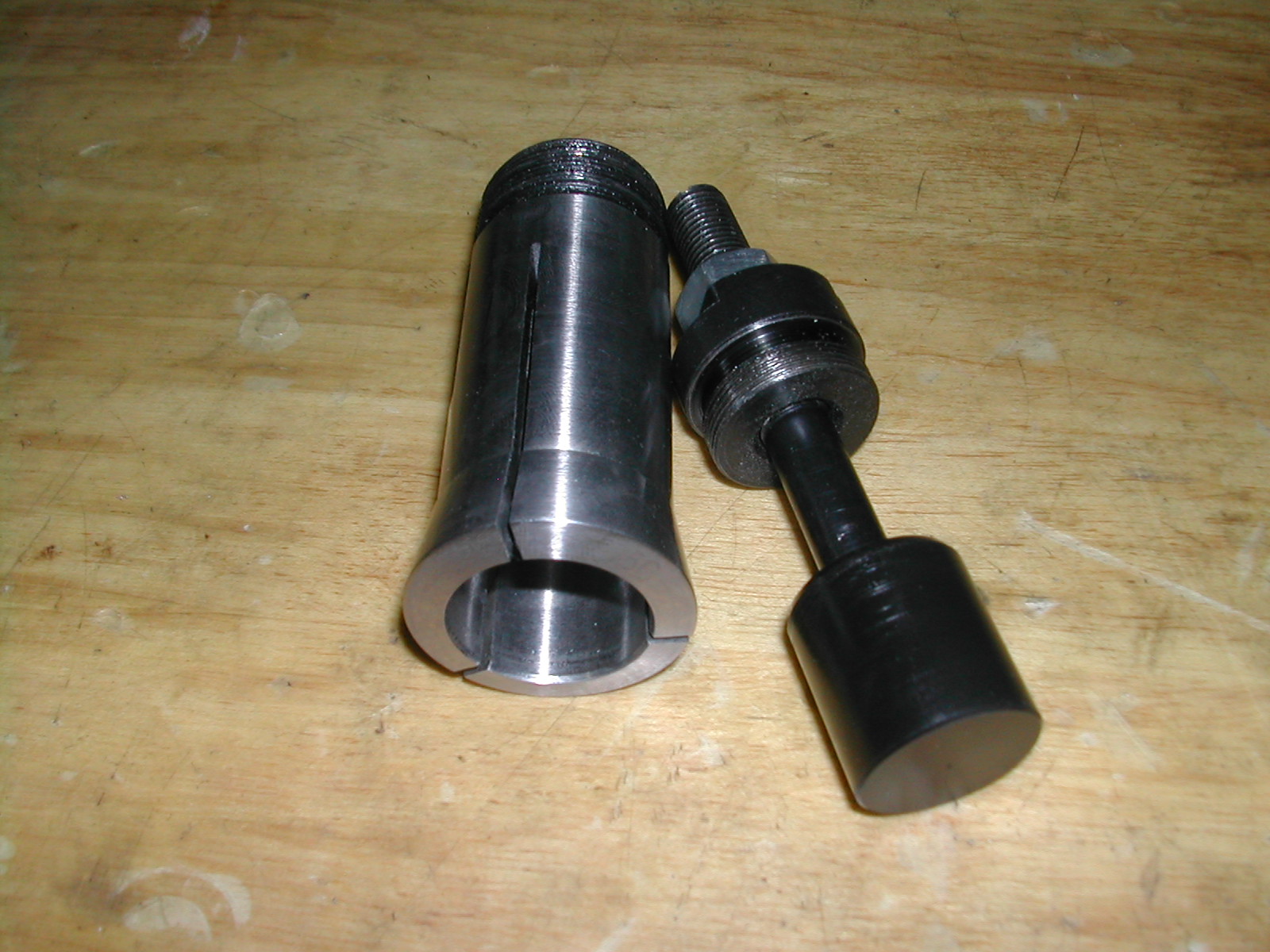 Now that I’m working with individual blanks, I turned a Delrin boss to fit the rod of my collet stop. Since the skirt is relieved, the collet stop needs to be larger than 3/4″ diameter to make contact with the piston skirt.
 With the collet stop mounted on a 1″ collet, all of the piston blanks were turned to the finished length of 0.875″ and chamfered.
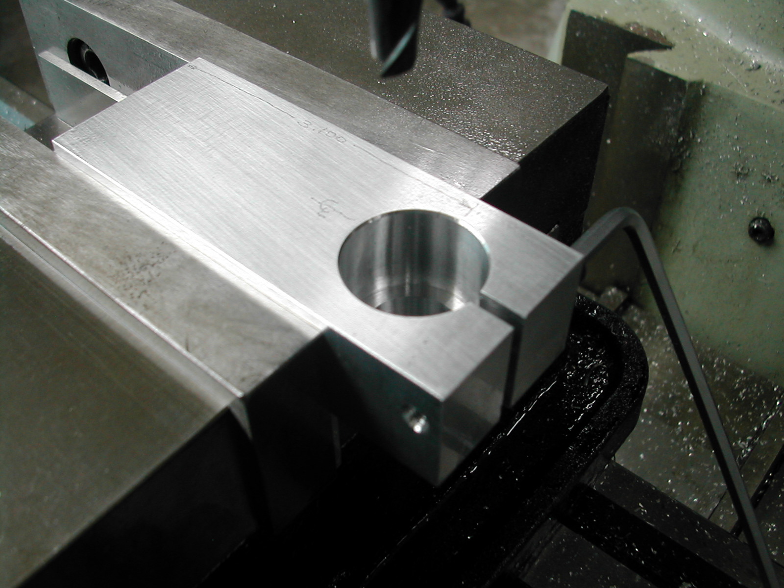 I made a simple fixture with a stepped hole to grip the pistons to mill the rod pockets. At this point, rotary orientation of the pistons does not matter and the pocket can be placed anywhere. I will later index off the pocket to locate the rod pin hole and the oil drain holes, so it’s important to accurately machine the rod pockets.
You’ll notice the jigs are engraved with location information – I’m planning on using these again for my 18 cylinder project!
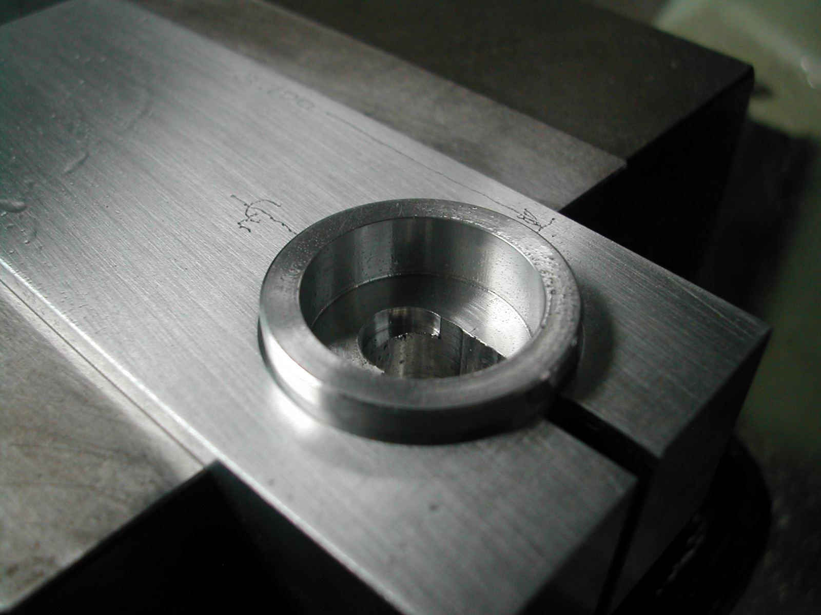 Here I’m roughing out the pocket by feeding with the quill and pecking with an 8mm endmill.
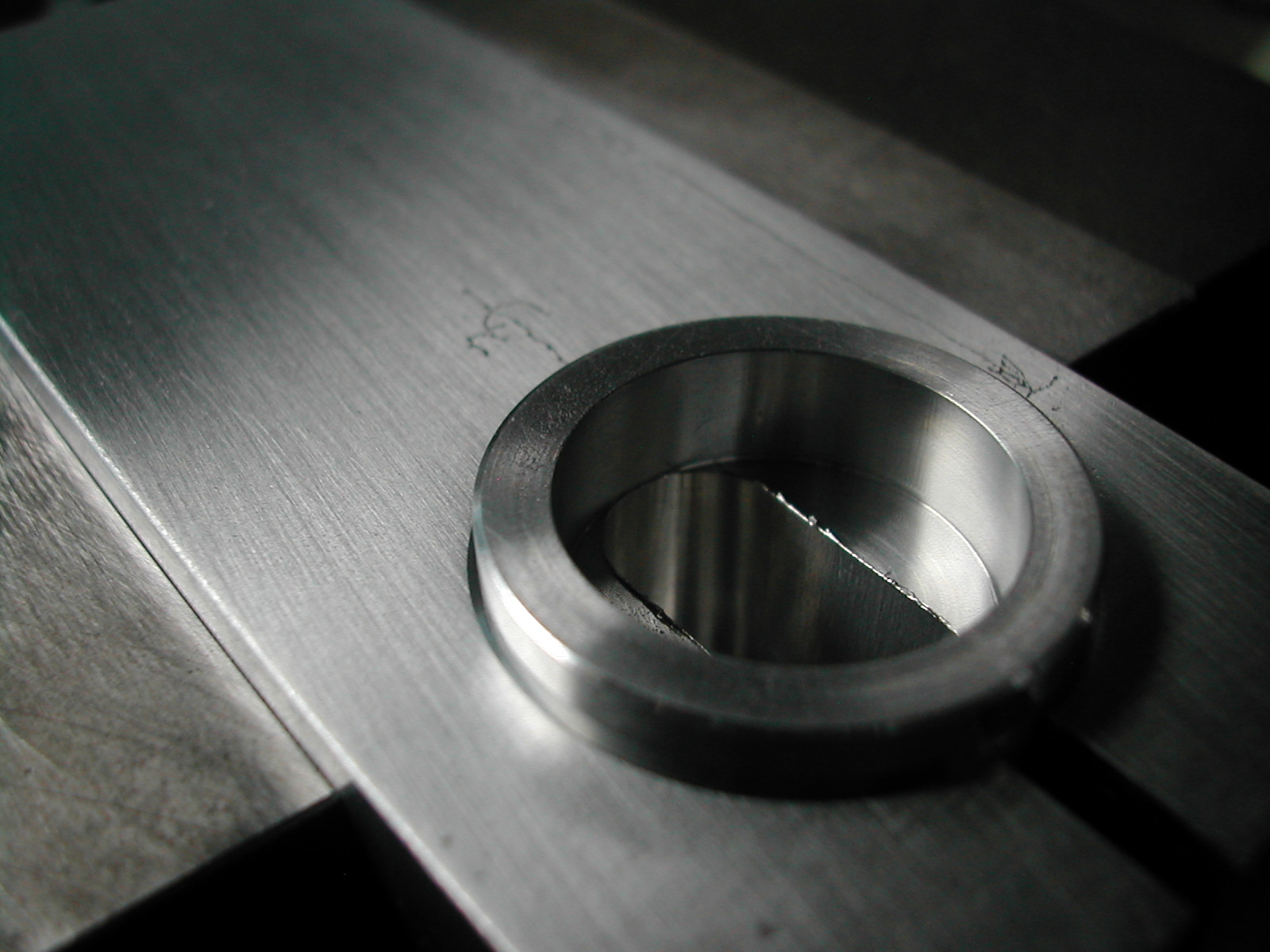 The next step is to feed the knee to the finish depth, and climb mill the pocket perimeter with the 8mm endmill.
 Once all of the pockets are finished, it’s time to drill and ream the wrist pin holes. The jig I’m using here is my own design, so I’m happy to provide the 050 Piston Special Tool #1 CAD model (AutoCAD 2010) if you want to duplicate it. This special tool is used to locate and drill the wrist pin holes and the oil drain holes in the oil ring groove.
The wrist pin holes are drill and reamed 0.1880″ for a close slip fit on the 0.1875″ wrist pins.
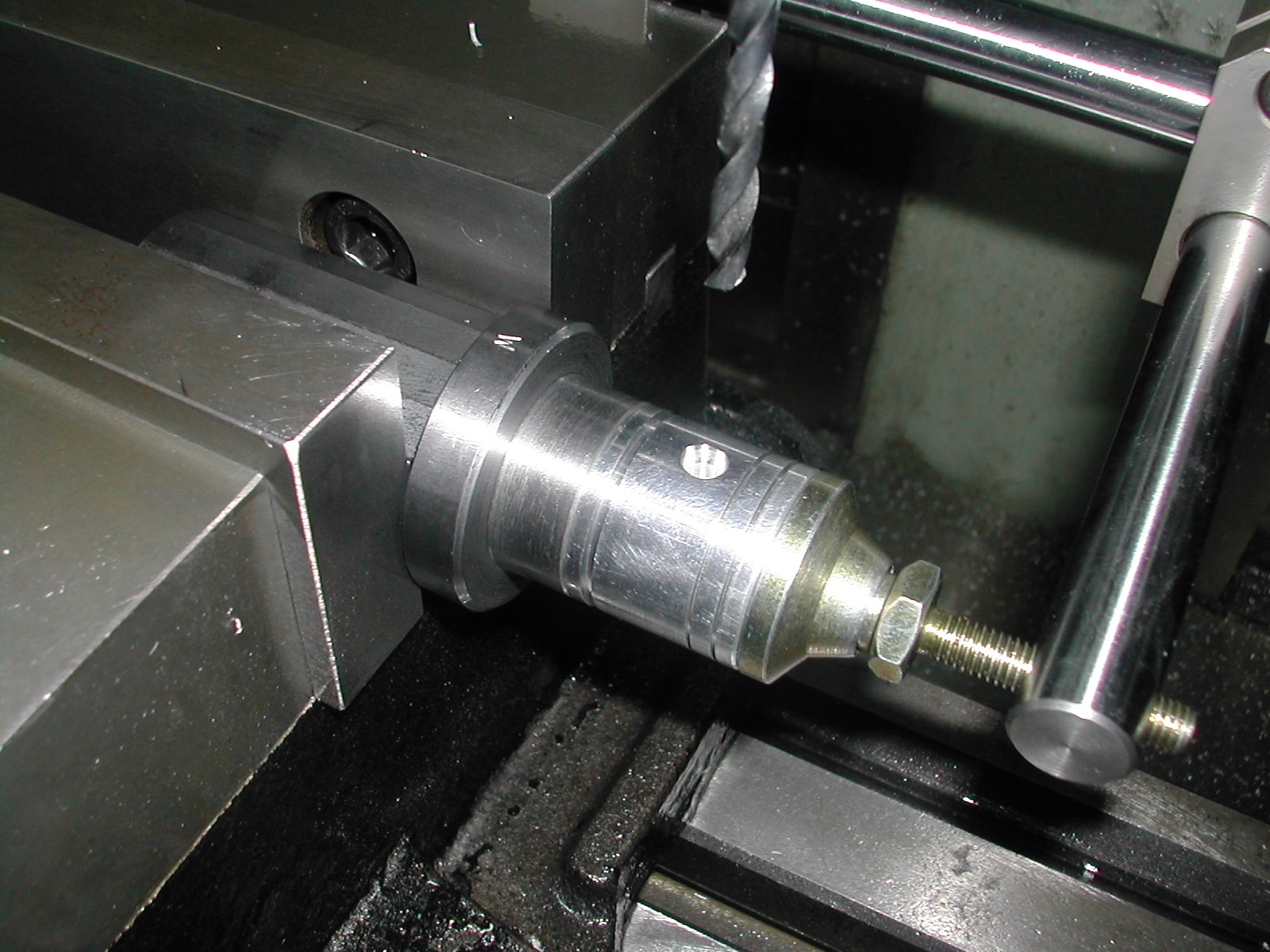 With the jig body clamped in the vise and the central locking pin removed, I’m using my vise stop with a swivel pad inserted where the stop screw normally goes to hold the piston on the tool.
The end of the vise jaw and the shoulder on the jig provide axial location, while the piston end of the tool is centered about the 16 flats on the clamping end of the tool. The tool accurately locates the rod pocket in the piston for drilling and reaming the rod pin hole.
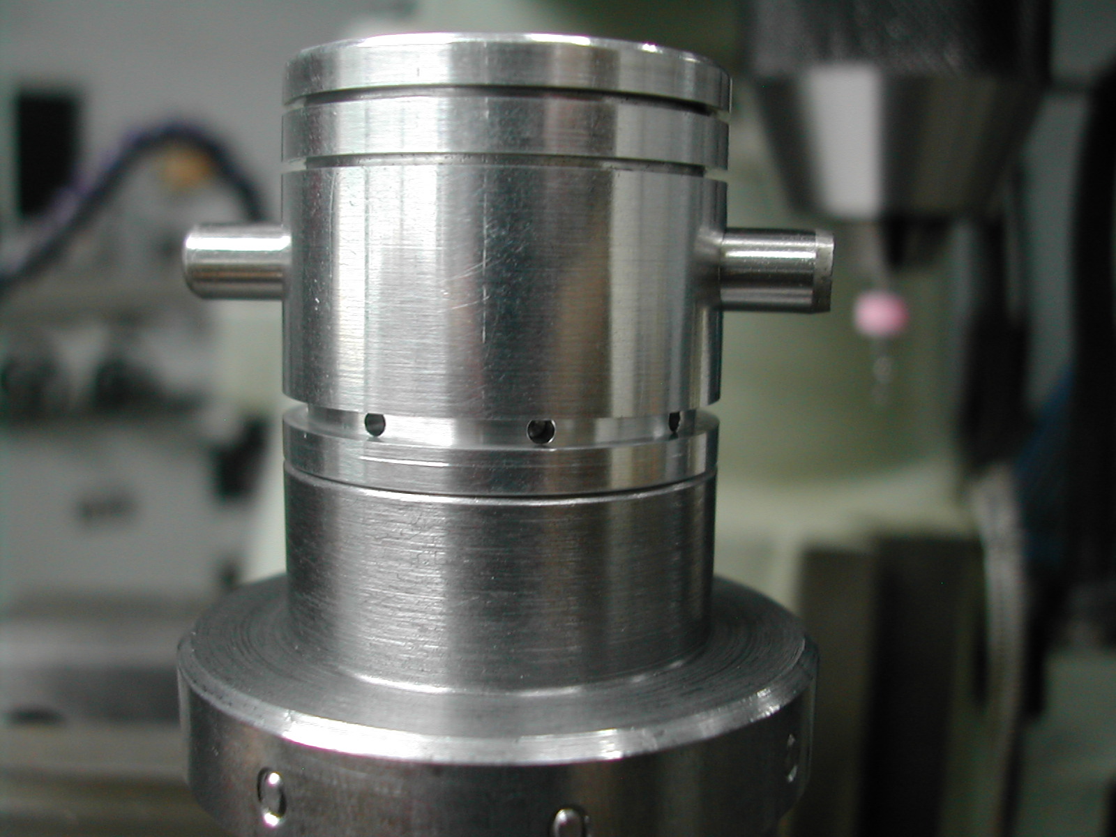
 Now that the wrist pin hole has been drilled and reamed in each of the pistons, we can remount them one by one using the central locking pin and a 3/16″ dowel pin through the wrist pin hole to hold the piston on the tool.
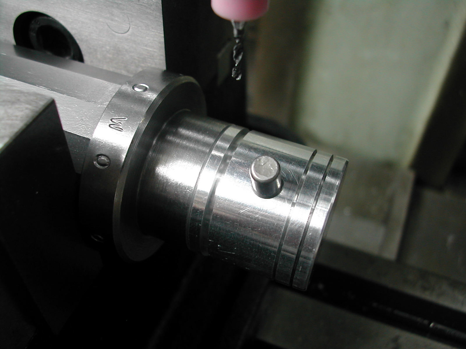
Notice the stamped letters on the tool? These indicate the tool position relative to the 16 flats for either drilling the wrist pin hole “W” or the oil drain holes “O”.
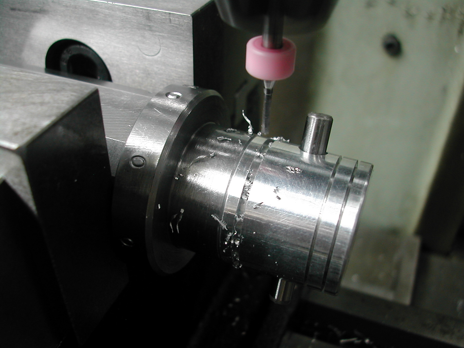 Using a #55 carbide circuit board drill, the 8 oil drain holes are then easily put in the oil ring groove by simply re-clamping the tool after each hole, making sure one of the “O”s is vertical each time and the tool shoulder is tight against the vise jaw end.
The short, carbide, circuit board drill is stiff enough to minimize wandering when starting the holes. This is important because it’s almost impossible to center drill these small holes.
 The holes are then carefully deburred by hand with a #54 drill.
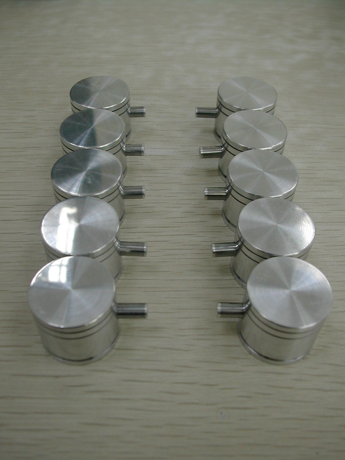
And here’s the finished set of pistons and wrist pins ready to go.
Disclaimer and License
All material, including the CAD drawings, relating to the construction of the Hodgson Radial presented on this site is free to use any way you see fit. However, no guarantees are made regarding the accuracy or correctness of the material presented here.
Links Used On This Page
(CAD drawings are in AutoCAD 2010 Format)