
- Hodgson Part 023, Housing
- Hodgson Part 024/069 Cylinder Studs & Value Adjusters
- Hodgson Part 025, Tappet Bushings
- Hodgson Part 027, Tappet
 The crankcase started life as a 125mm diameter by 300mm piece of Aluminum 7075-T6. I bought a stick of this long enough to make the front cover, crankcase, rear seal plate, air guide, impeller, and a few fixtures. The diameter was needed to accommodate the crankcase so I did end up wasting a little material on the other parts. To make the crankcase, I sawed off a 4.75″ section so I could move everything closer to the chuck.
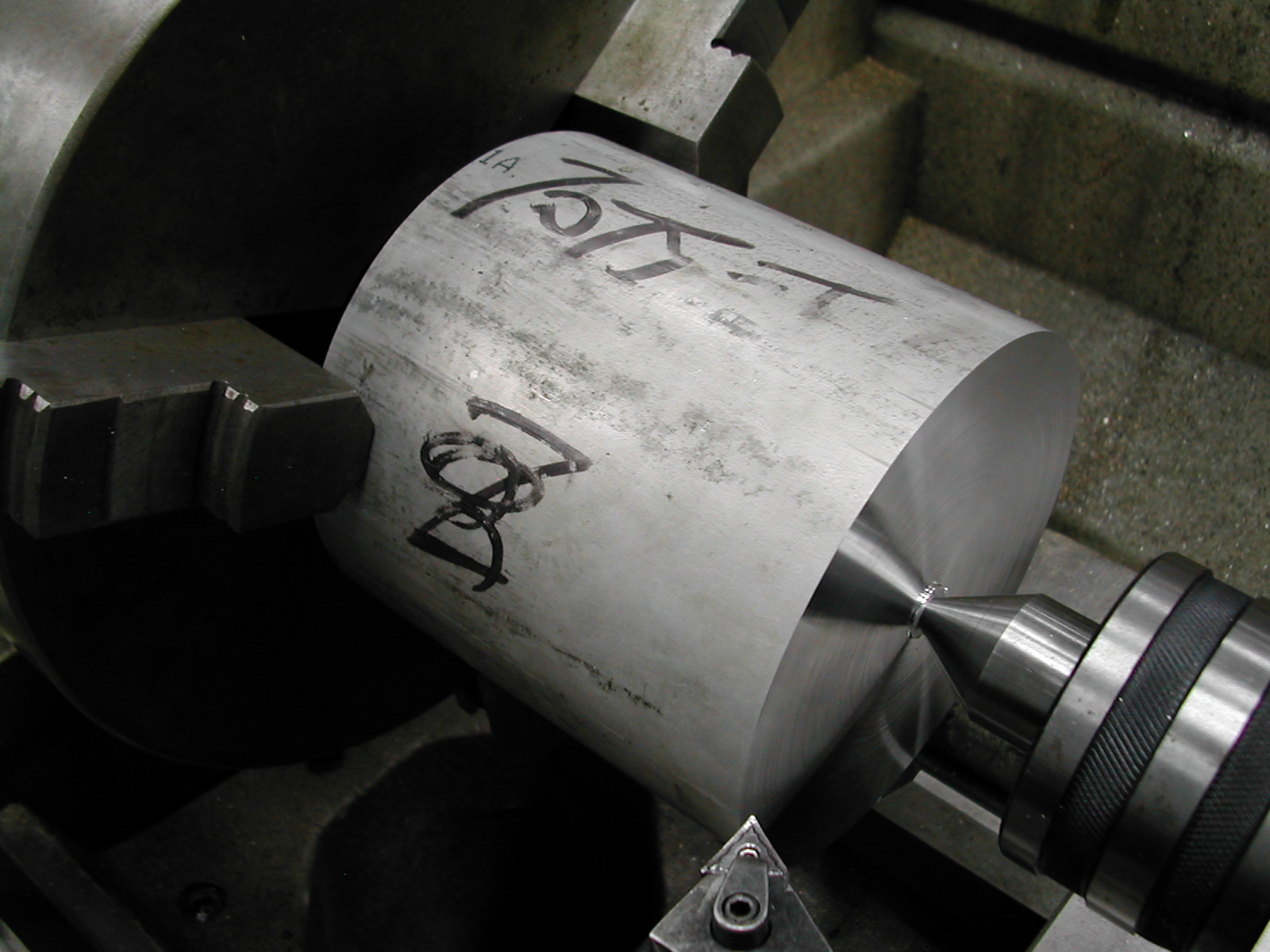 Here I’ve chucked on 3/4″ as tight as I could get it by hand, then center drilled for a live center and taken a skim cut on the end. The end nearest the chuck will become the front end of the crankcase. I chose this for a couple of reasons that will become clear as we proceed.
To keep from shuffling back and forth on the plan drawings at the lathe, I combined all the necessary dimensions on a single AutoCAD drawing.
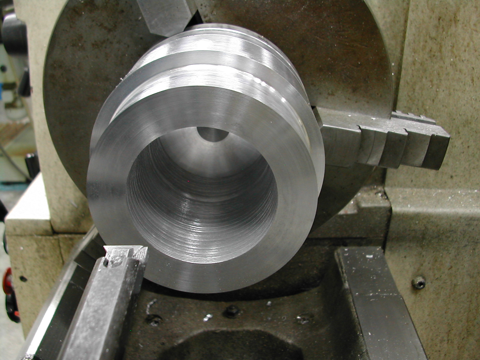
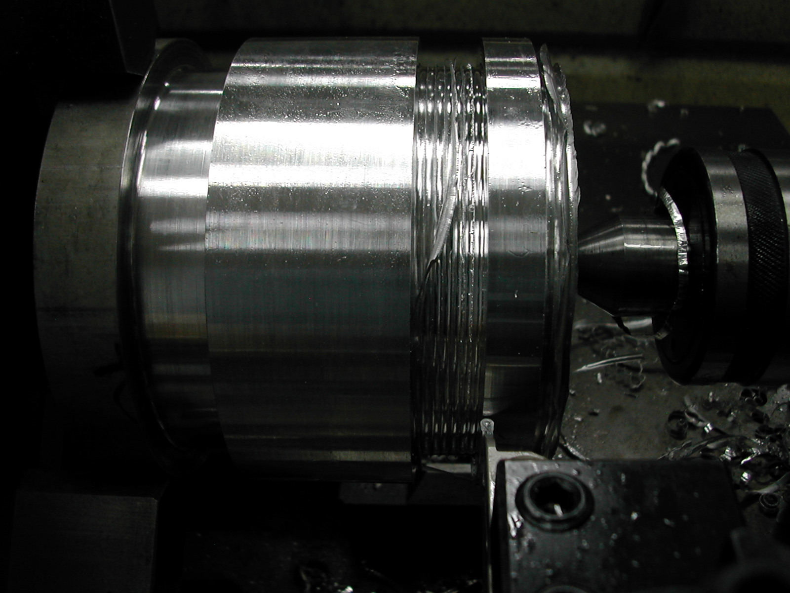 The tool I’m using here is a 1.5mm radius (0.059″) insert grooving and profiling tool. The insert is a MRMN300-M in a MGEHR 1616-3 toolholder both made by Korloy. You can see that I’ve roughed out the fore (lifter) end of the housing and I’m now roughing the aft (intake) end.
The technique I’m using is to plunge the tool like a grooving tool to depth and then stepping over and repeating. After the bulk has been removed by this technique, I then feed across the part at depth to clean up. At this point, I’m just roughing leaving 0.025″ on all surfaces.
 With the outside roughed out, the next step will be to rough the inside portion.
 Starting with a 24mm drill, the largest I had on hand, I then bored with a conventional boring tool at about 0.100 width of cut per pass to 2.825″. I didn’t want to be too aggressive with only 3/4″ held in the chuck jaws.
This boring was completed in 4 stages at 1″ deep per stage to make sure the chips didn’t pack in the bore and possibly knock the part out of alignment.
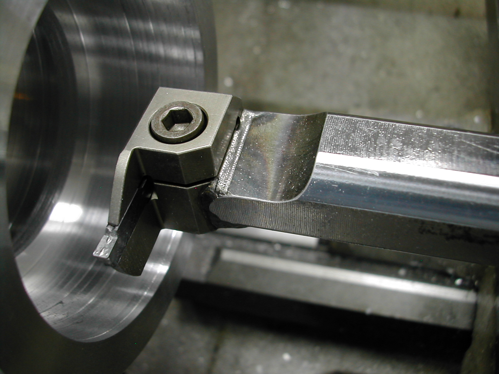 This is a custom tool I made a while ago from a Korloy MGEHL 1616-3 (the left hand version of the tool used on the outside) The shank was cut off and the business end was welded at right angles to a 25mm bar to make an internal grooving and profiling tool. This tool lets me groove to a little over 5/8″ deep in a minimum bore of 1.7″.
Here it’s outfitted with a MGMN300-M insert which is 3mm wide with a 0.4mm (0.015″) corner radius and I’ve used that to rough the internal configuration leaving 0.025″ on all surfaces using the same plunge-stepover process as the outside work.
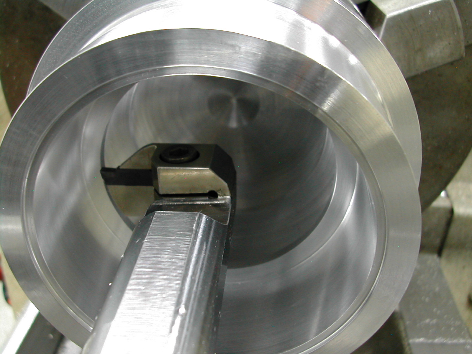
 The beauty of these inserts is that I can easily work on both sides of a shoulder without having to change tools. This enables me to just offset by 3mm when working on the opposite face of a feature like the cylinder band in the center of the crankcase.
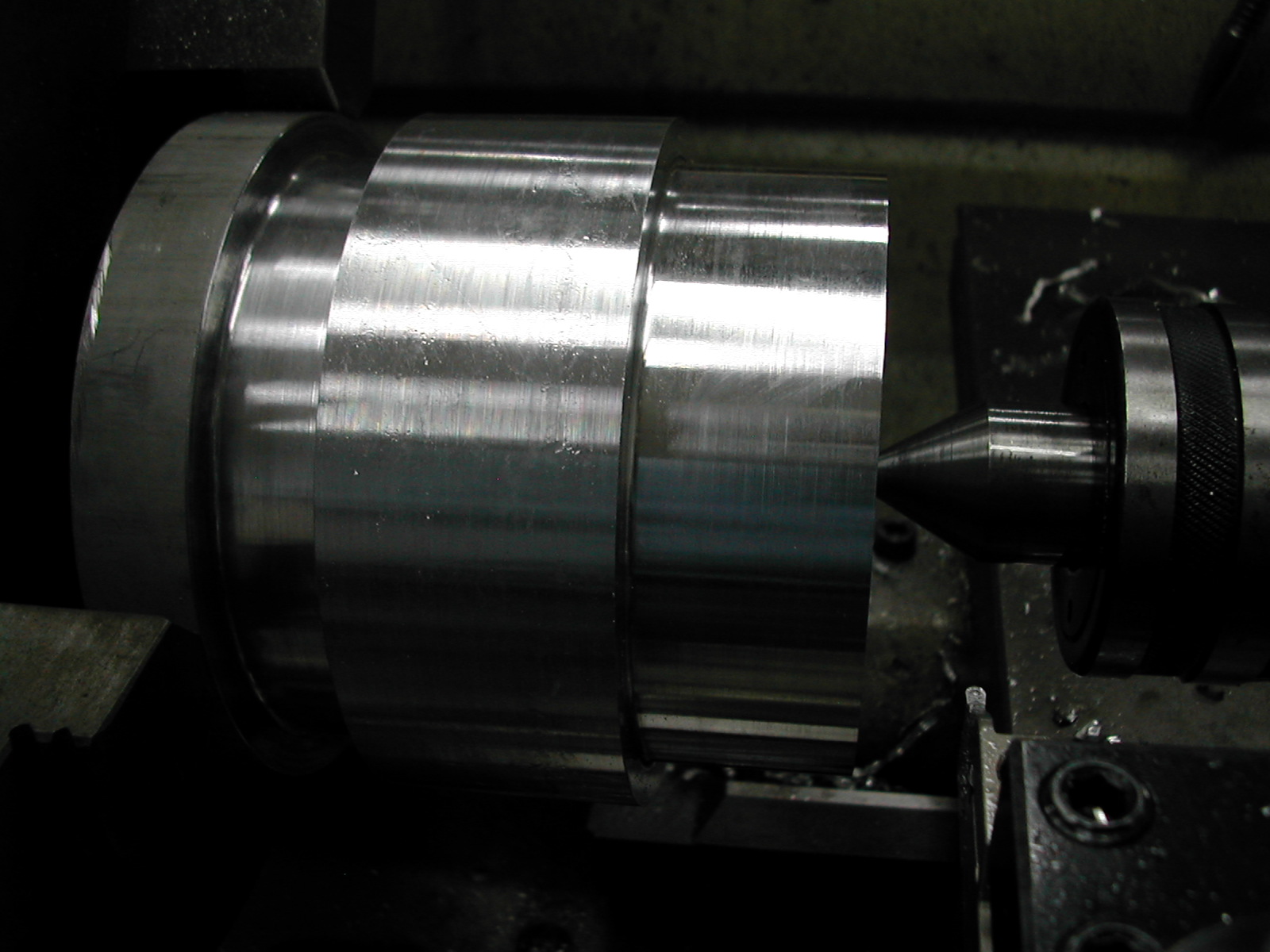
So the next step was to make a light facing cut to set the zero datum and make sure the crankcase end was true in case it got knocked about a little when roughing, and then finish the outside of the part.
Theoretically the cylinder band should finish at 4.789″ O.D. I left it oversize, but made sure to take a skim cut so I could measure the diameter later and use it to set my facing cutter in the mill.
 With the outside finished, I went back to my custom boring bar and finish turned the complete inside including the step for locating the rear cover. One of the reasons for making the chuck end the front of the crankcase was so that I could easily measure the this step. It would have been much more difficult had the crankcase been reversed.
It’s hard to see in the photo, but all of the inside was turned in this single setup ensuring all outside and inside diameters were concentric. A short piece of ground 3/8″ tool steel laid across the internal flanges and a depth mike was used to check their locations.
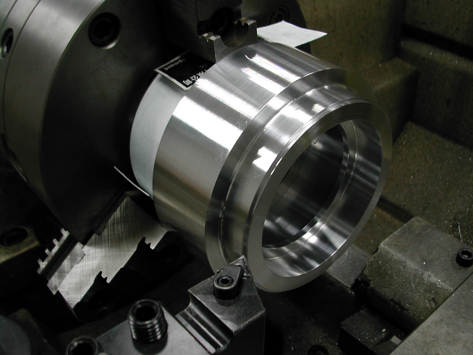
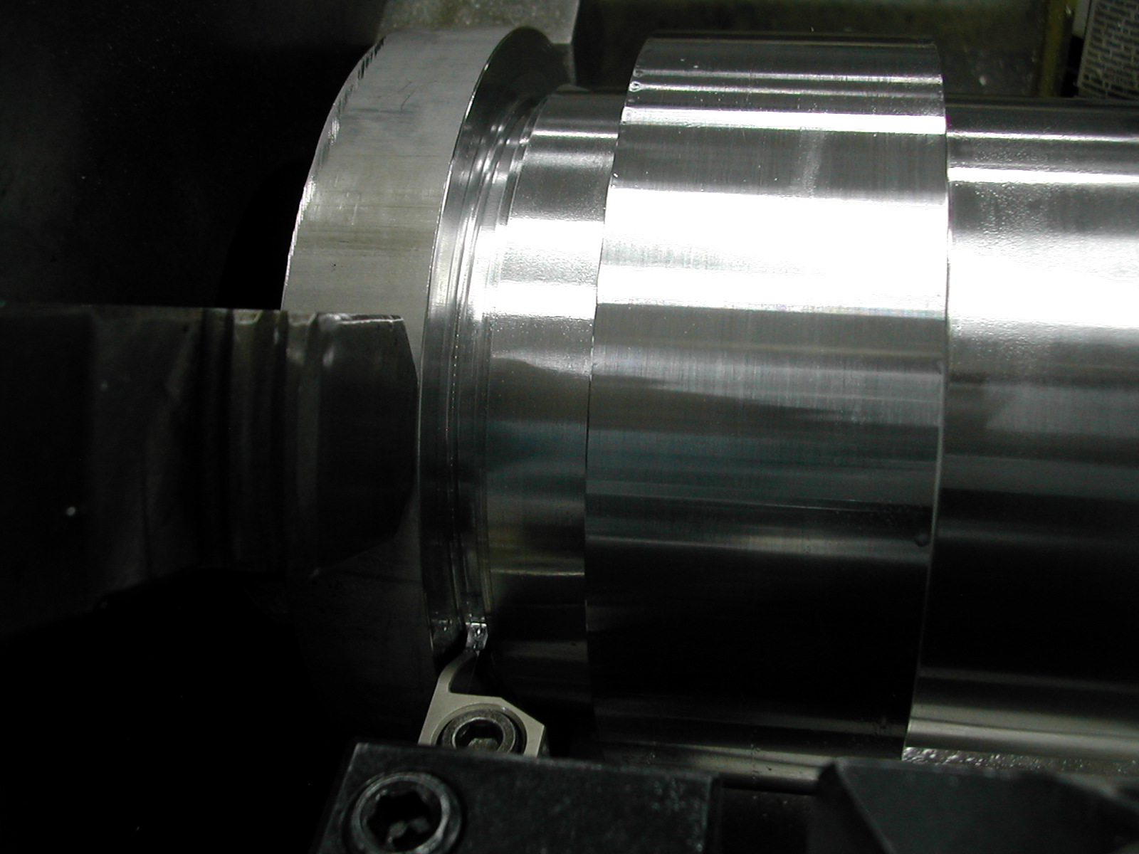 I’ve now changed to the MGMN300-M insert on the O.D. holder and added the locating step for the front crankcase housing. Then I used the same tool to part off the crankcase.
 I ran the parting tool in to 3.4″ diameter and I’m finishing off the last 0.025″ with a hacksaw. I’d hate to have the part catch and get dinged up at this point.
 I’ll use the waste here to make a fixture for the rotary table to do the milling and drilling on the crankcase in the mill later.
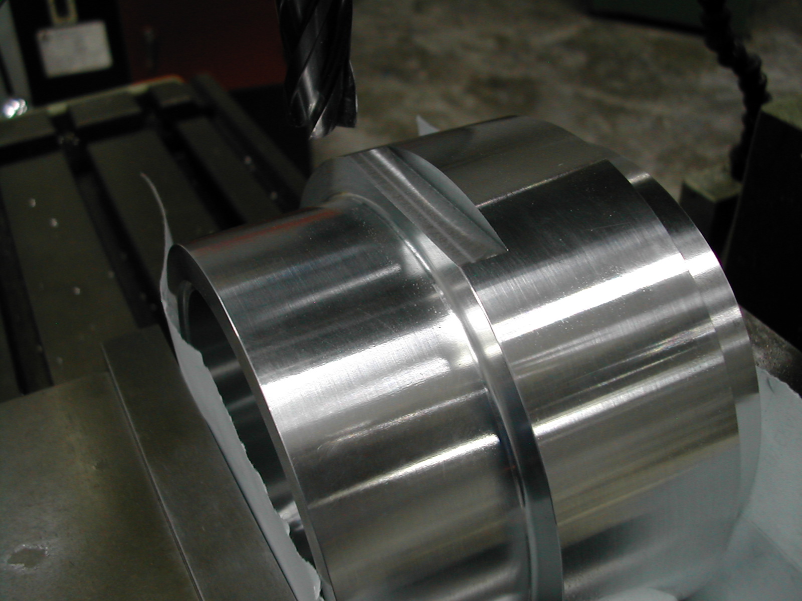
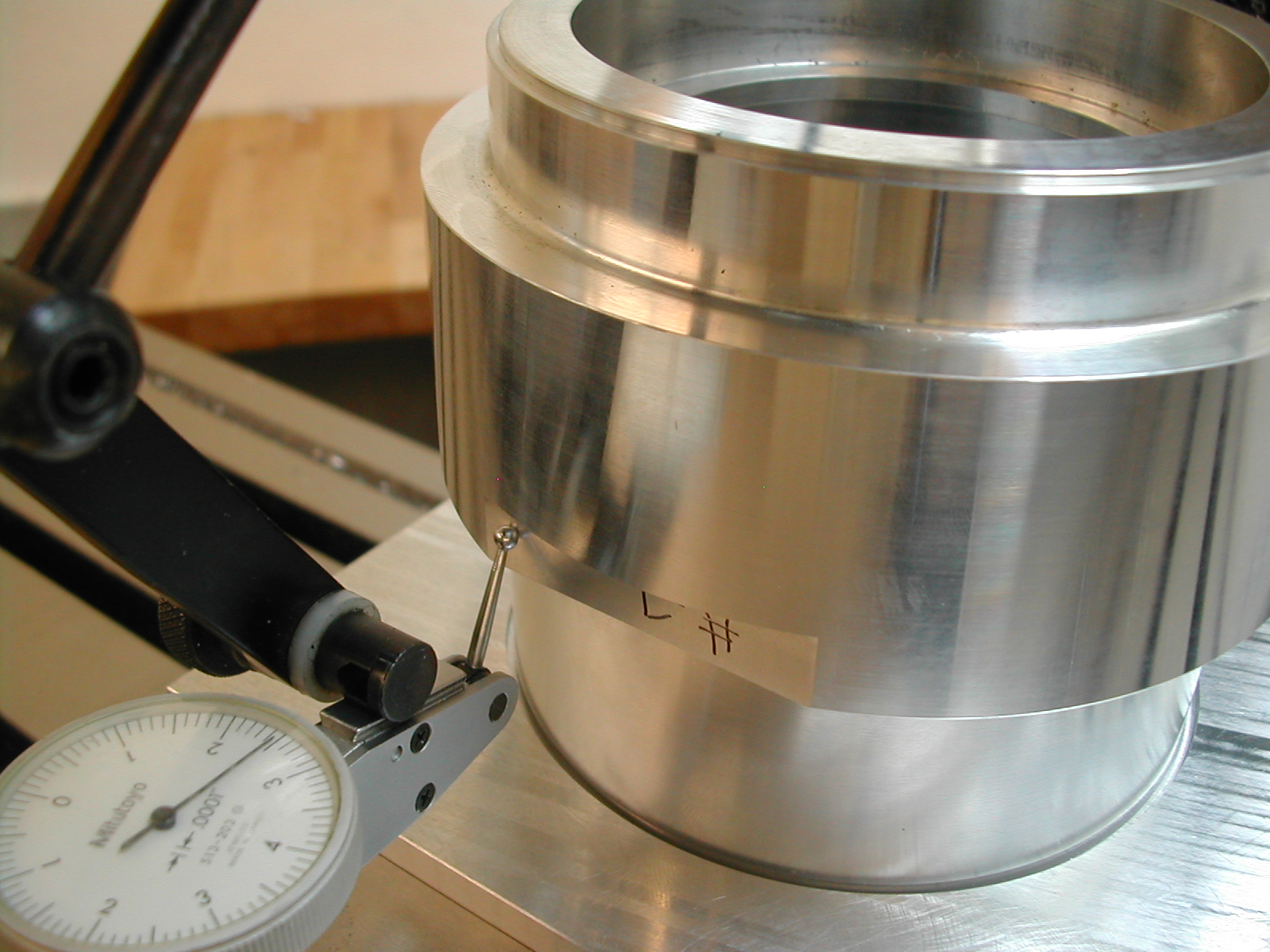
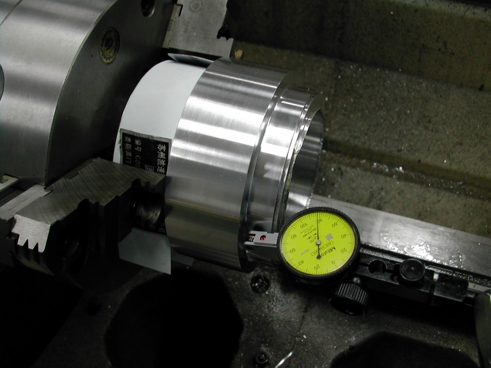 With the part flipped around I’m making sure the flange runs true before centering the crankcase.
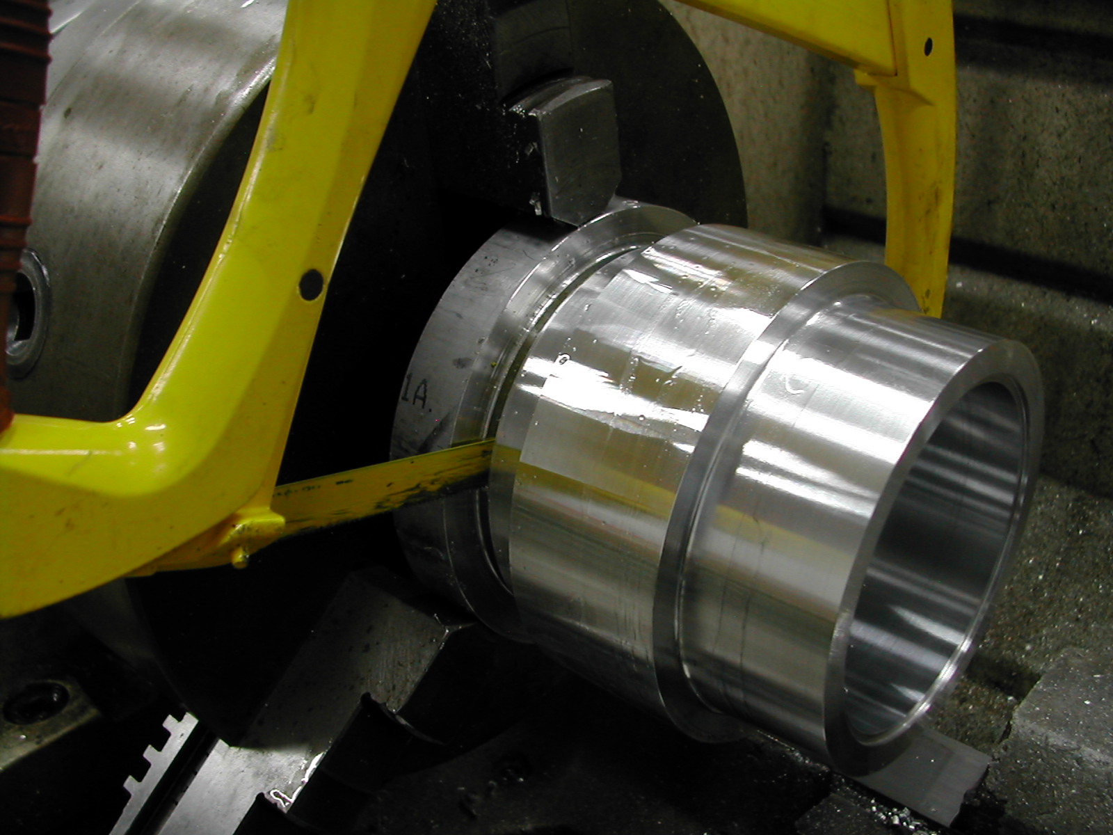
Now the main reason for turning the crankcase from back to front becomes obvious – I can chuck on the longer surface of the intake end.
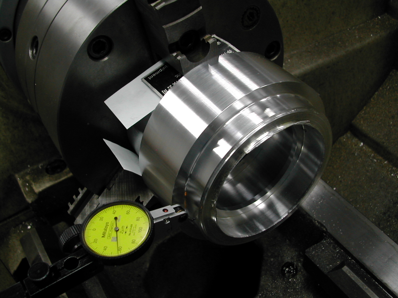 With the crankcase running perpendicular to the lathe centerline, I can now use the adjustable chuck to center the crankcase. If I didn’t have an Adjust-True chuck, I would have had to use a 4-jaw chuck for this operation as a “self-centering” 3-jaw chuck really isn’t.
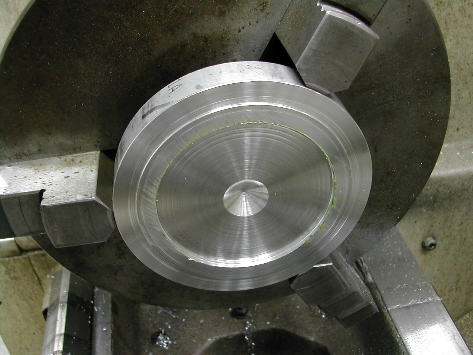
 The last turning operation is to face the crankcase to the finished length. This is the only surface on the crankcase that is not perfectly concentric or square with the other surfaces; it’s precision depends on the accuracy of my previous squaring and centering operations.
 To prepare the housing for subsequent mill operations, a flat was milled on what will later become the #1 cylinder boss. This flat will be used to indicate the crankcase for drilling and tapping the holes in the front and rear faces.
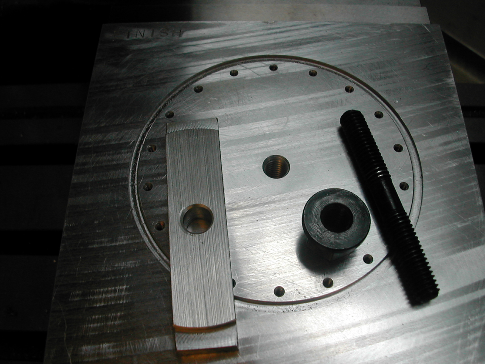 The tooling plate previously used to fixture the front and rear covers will be used to fixture the crankcase for its milling operations as well.
 A scrap of aluminum is used in conjunction with a 3/8″ clamp stud and nut to clamp the crankcase with the front face up.
 The previously milled flat is indicated in and the crankcase rotated to square the crankcase to the mill’s axis. Once square, the crankcase is indicated to locate the center.
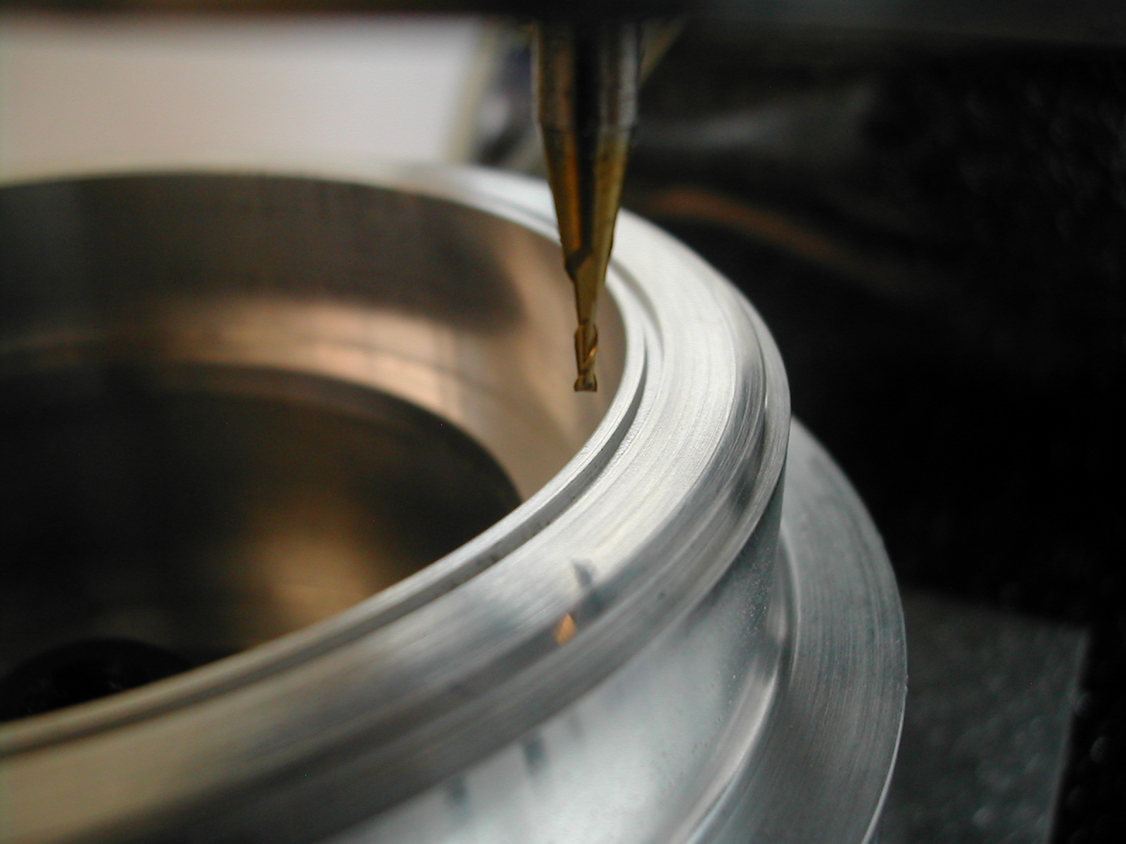 Here, I’ve added a 1.2mm wide x 0.8mm deep groove on the face for a 1×88 metric O-ring that will seal the front cover. This O-ring is not in the plans and there is very little room for it to fit. Because of the lack of space, I needed to use a 1mm O-ring because a 1/16″ O-ring was too large.
Unfortunately, 1mm O-rings are not available with an 88mm ID, nor is 1mm cord stock available. I ended up cutting and combining four 1×25 O-Rings to make the needed 88m ring.
 Next up were the #4-40 tapped holes and the oil drain hole in the front main bearing flange and then the 18 #4-40 tapped holes for the front cover.
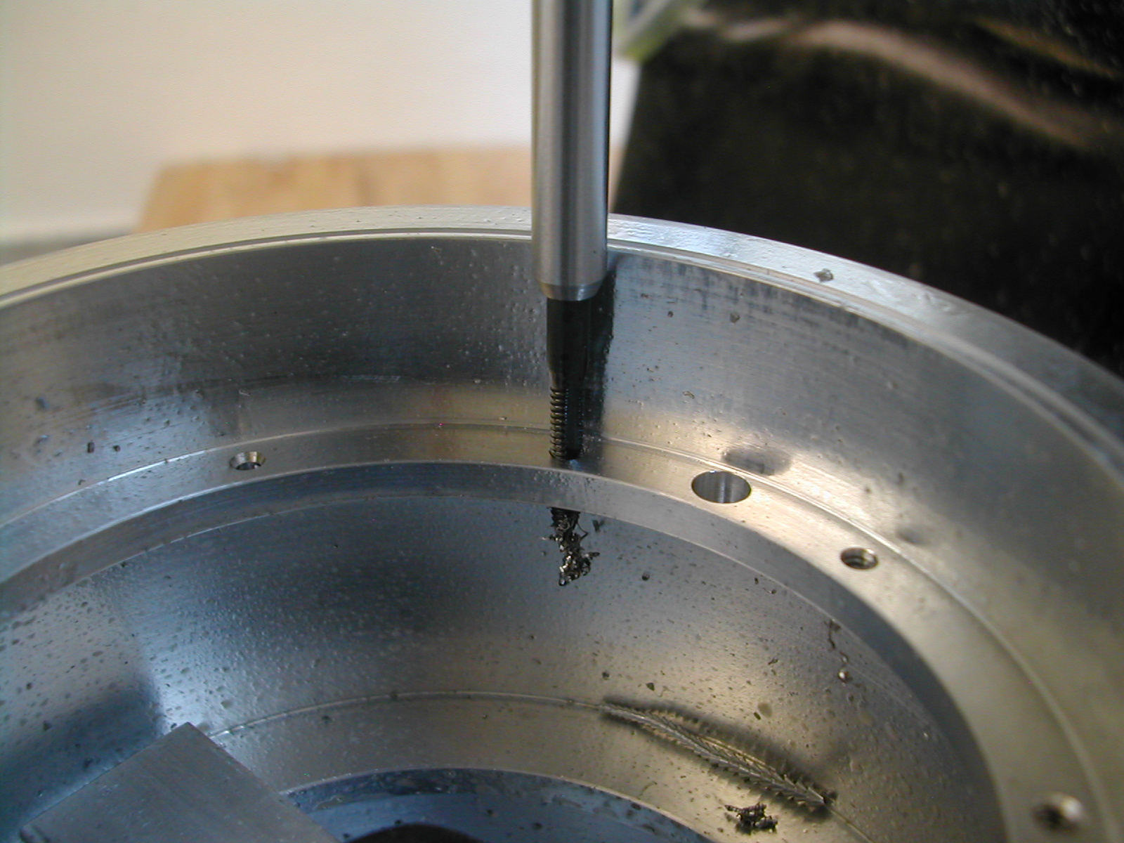
 The crankcase was then flipped, re-indicated both square and to locate center, and the rear bearing flange was drilled and tapped for its 9 #4-40 screws, and the 9 #6-32 scerws for the rear cover.
In this image you can see the special extended tap I made to reach the bearing flange. I made both and extended tap and an extend drill by Loctiting the a regular Jobber-length drill and tap into some scraps of 4mm drill rod.
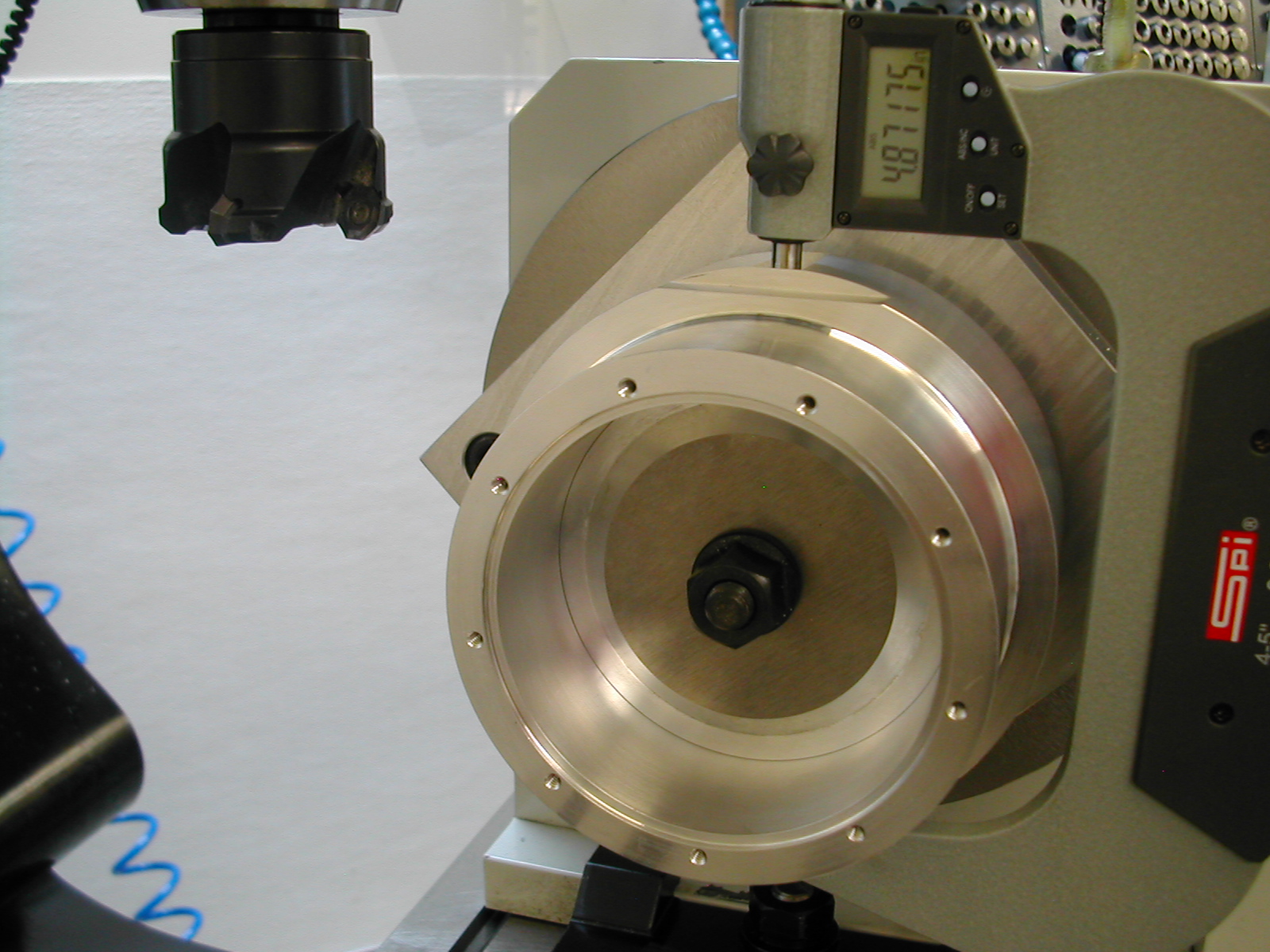
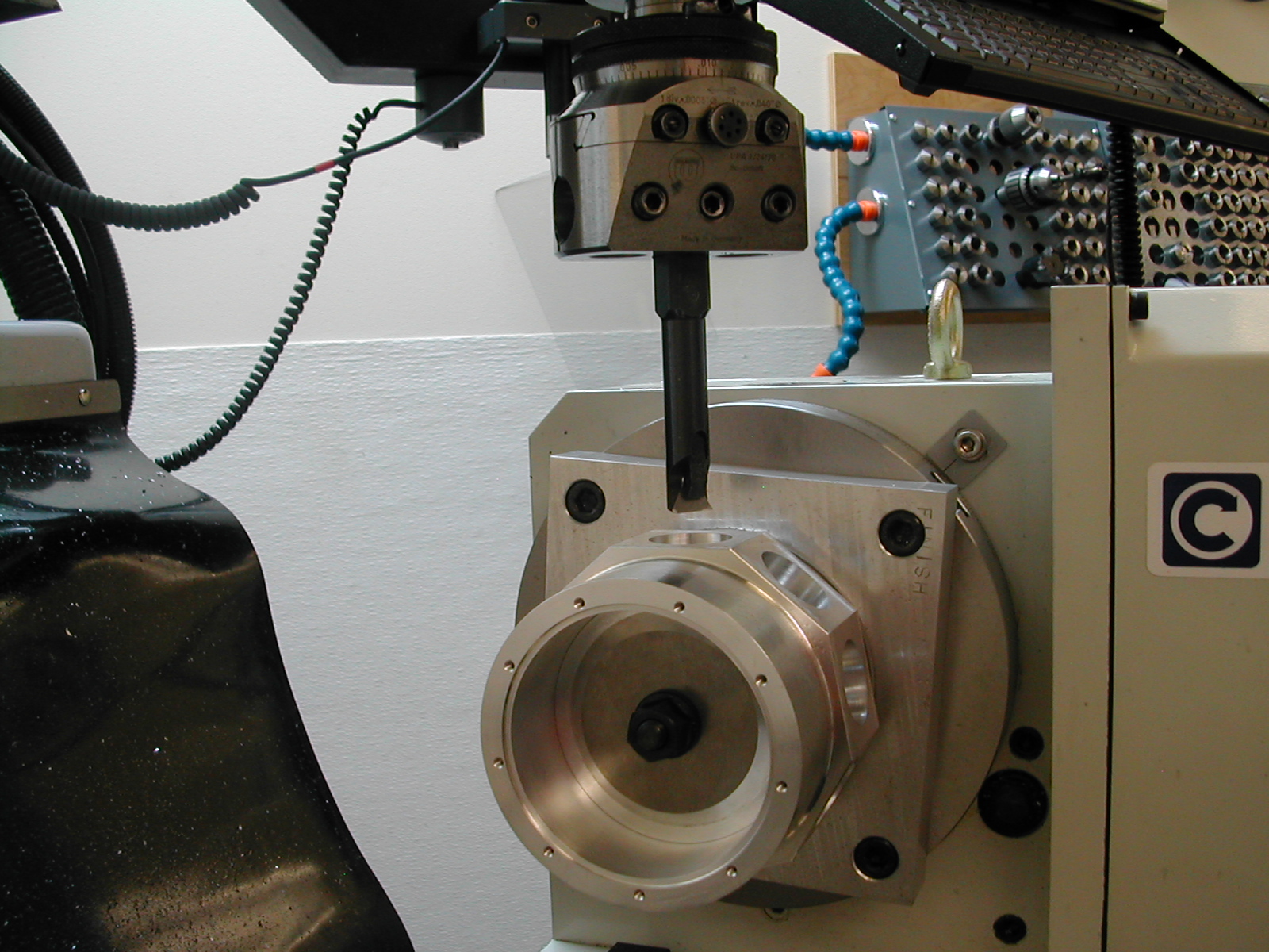
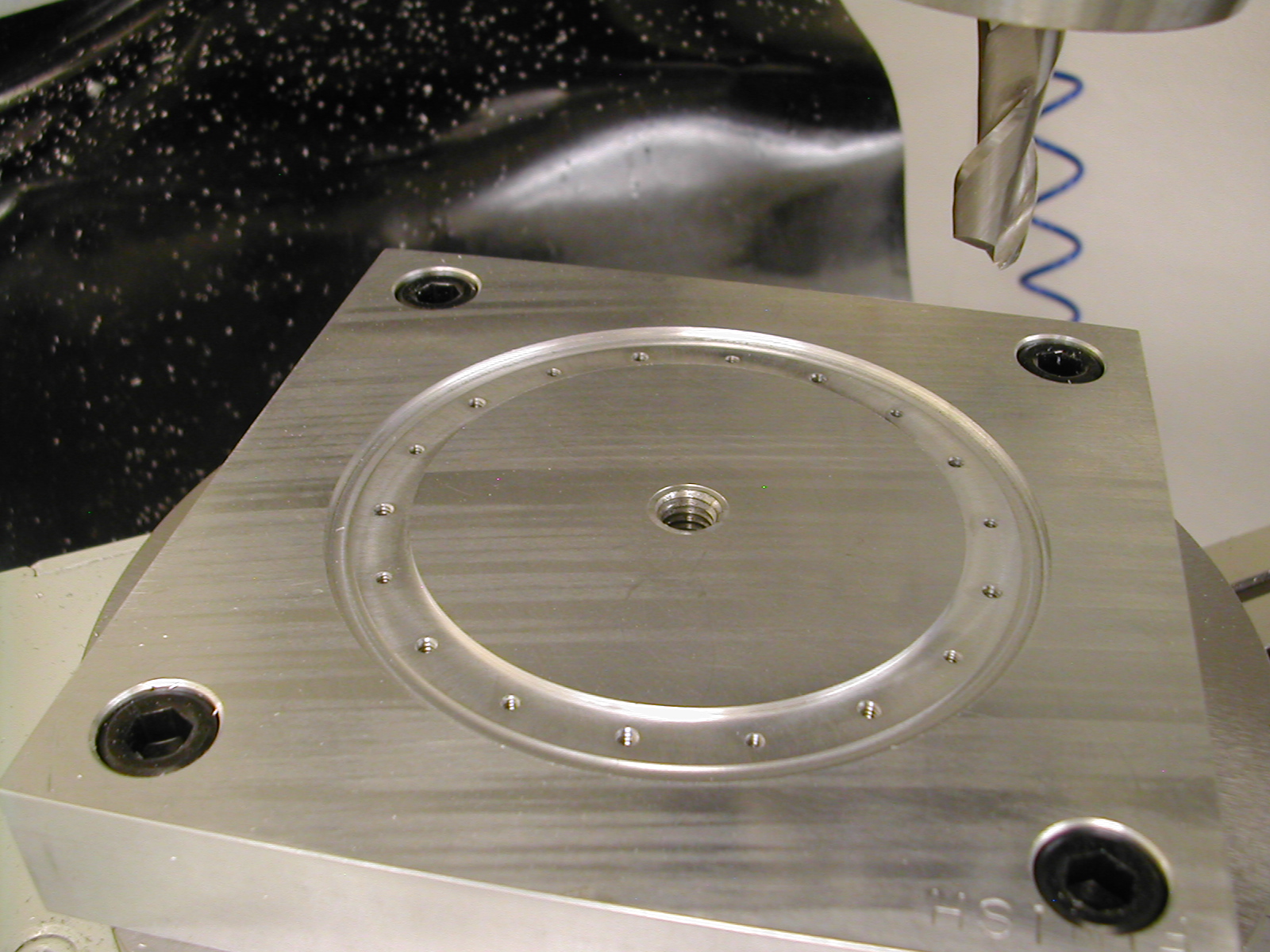 For the next setup, I’ve mounted the tooling plate to my rotary table and set up the rotary table in the horizontal position on the mill table. I’m machining a Ø3.374″ x 0.06″ boss to register the inner diameter of the front of the crankcase. I’m doing this in-situ to ensure it is concentric with the rotary table centerline.
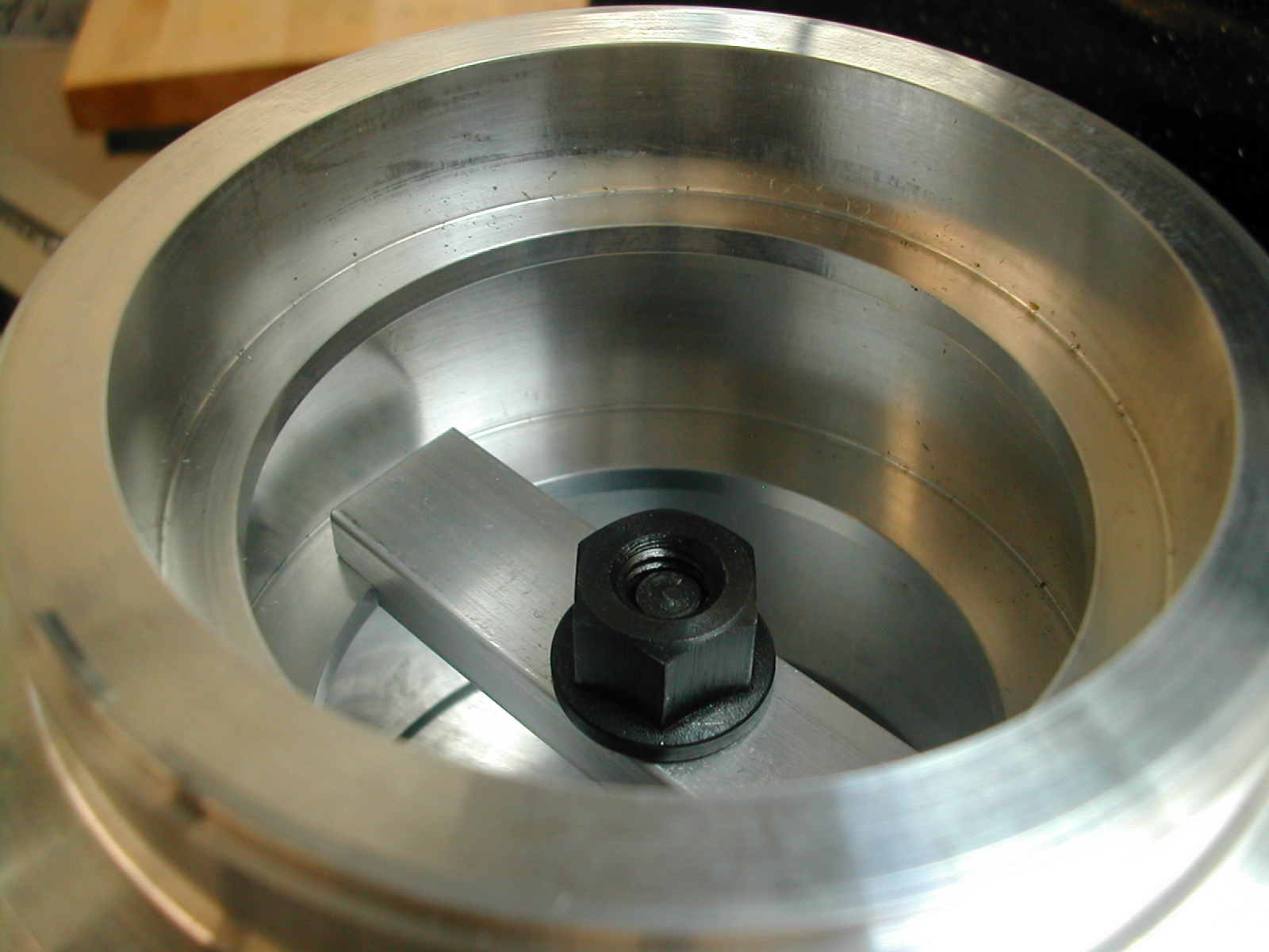
 The crankcase is mounted over the boss with a clamping plate, clamp stud, and nut and secured finger tight. The rotary table is then indexed to 0.00° and the crankcase rotated by hand and aligned with an indicator to orient the #1 cylinder notch, and then the clamp stud is securely tightened.
 With the crankcase mounted to the rotary table, the table is moved to the vertical orientation on the mill table and indicated to align the crankcase centerline with the X-axis. The crankcase is then centered in Y using an edge finder.
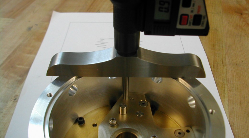
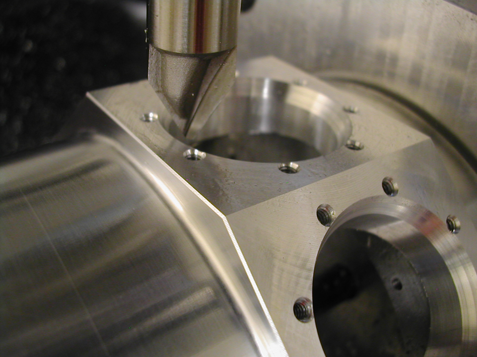
I’ve made a small test cut with my face mill and I’m measuring to calculate the final amount to come off.
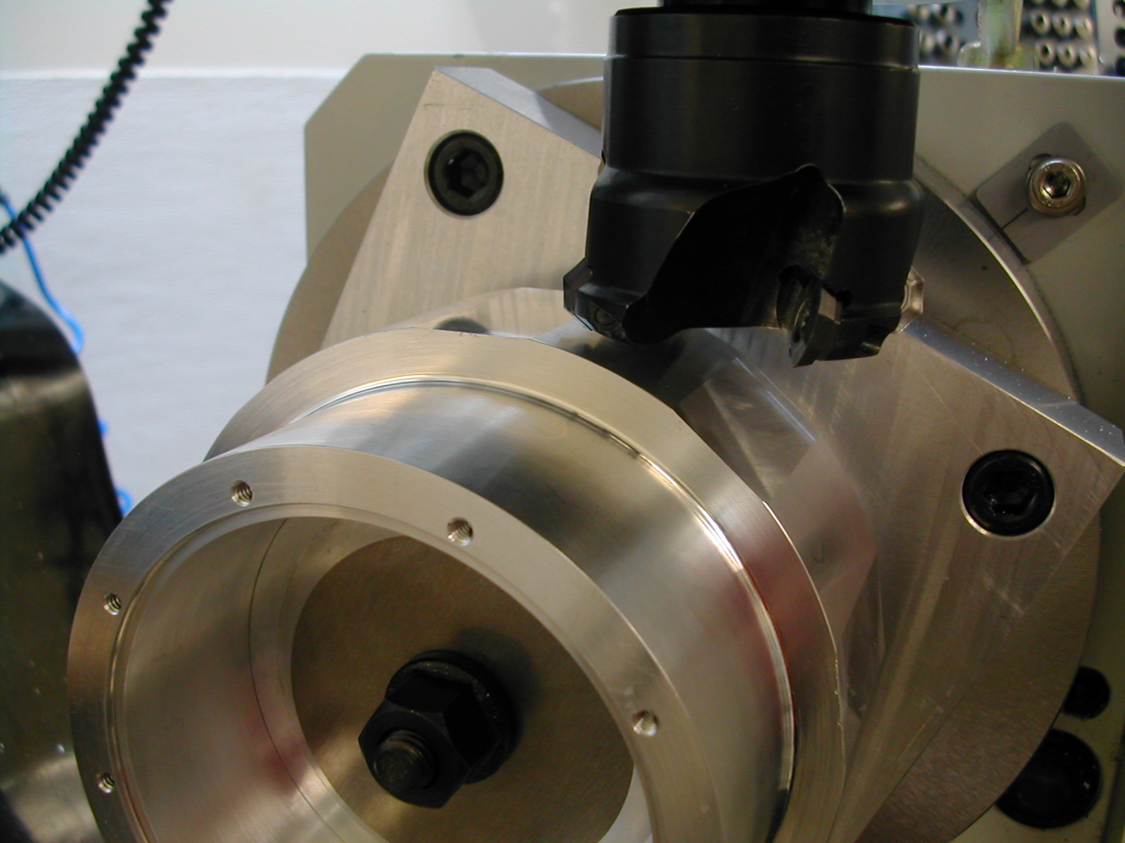 I then proceeded to make a series of small cuts (around 0.050″ per pass so as not to risk moving the part on the fixture) all the way around before changing depth, repeating this until the final depth was reached.
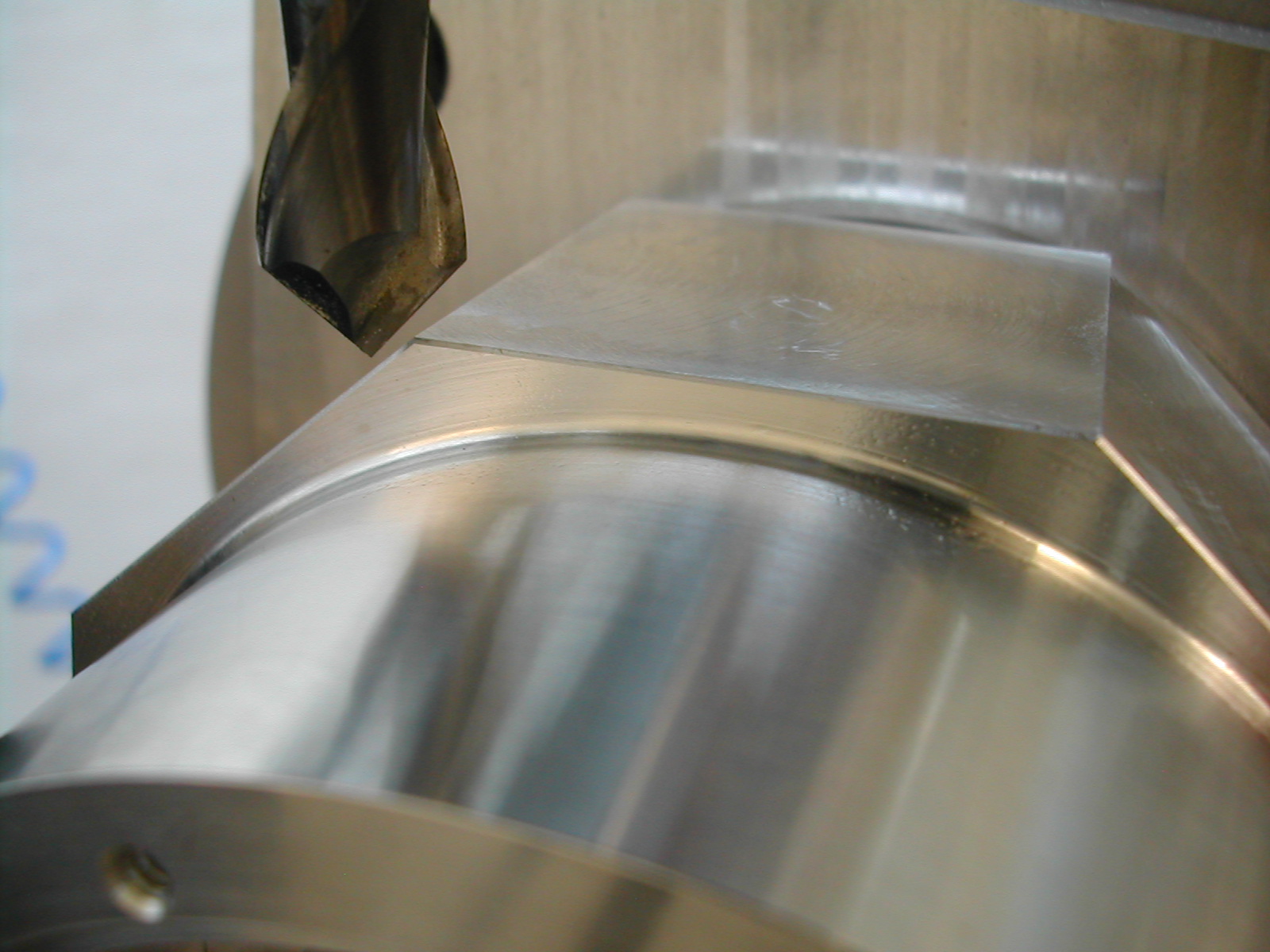 With all the faces at the final depth, I used a chamfer mill to break the front and rear edges of the cylinder facets.
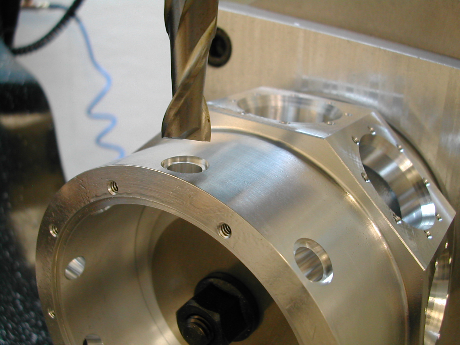
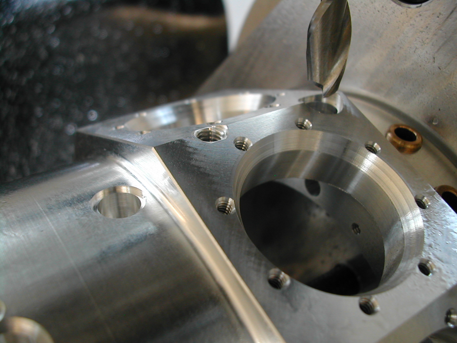
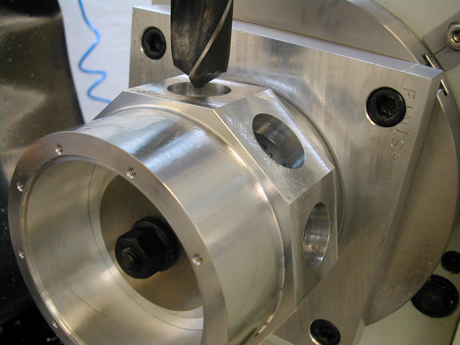 I worked my way up to a 1.0″ drill to open up all of the cylinder skirt bores.
 I then proceeded to bore all the holes to the same diameter before increasing for the next pass around until I reached the finish size. That’s my $300 eBay Wohlhaupter boring/facing head that puts any Criterion boring head to shame – I still can’t believe how smooth, easy, and accurate the tool-less adjustments are.
 Center drilling and tap drilling for the cylinder studs was fairly straight forward, but the corners of the fixture plate created some clearance problems when trying to use the drill chuck to hold the short #4-40 tap.
I ended up kluging up a sensitive tap chuck with a DA collet extension loosely held in a 3/4″ collet in the spindle. The DA extension was then turned by hand to run the tap in and out.
 This 30° chamfer is another modification I added. It’s an o-ring seat for a silicone 1/16″x1-1/8″ o-ring. This should seal the cylinder to prevent oil leaks and the silicone o-ring should be good to 400°F.
A regular 45° o-ring gland would have cut well into the cylinder head bolt circle, so I recalculated for a 30° gland keeping the same recommended percent o-ring compression.
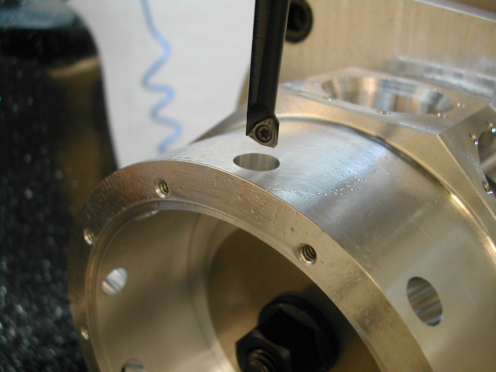 Here I’ve rough drilled the intake pipe holes and I’m finish boring them to size. I could have reamed, but I like the nice surface finish the boring head gives.
 I’m adding the 0.055″ deep o-ring seat with a 7/16″ endmill. I went a little shallower here because I’m adding a corresponding c’bore to the intake mounting plate.
 Next the #4-40 holes were center drilled, drilled and tapped for the mounting plates and that finished up the rear side of the housing.
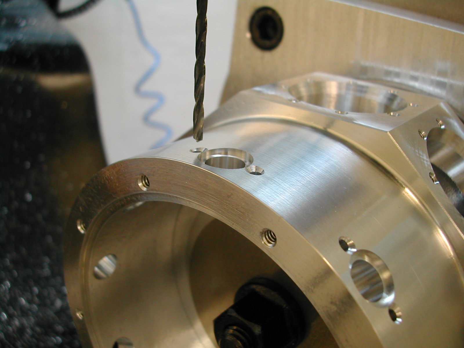
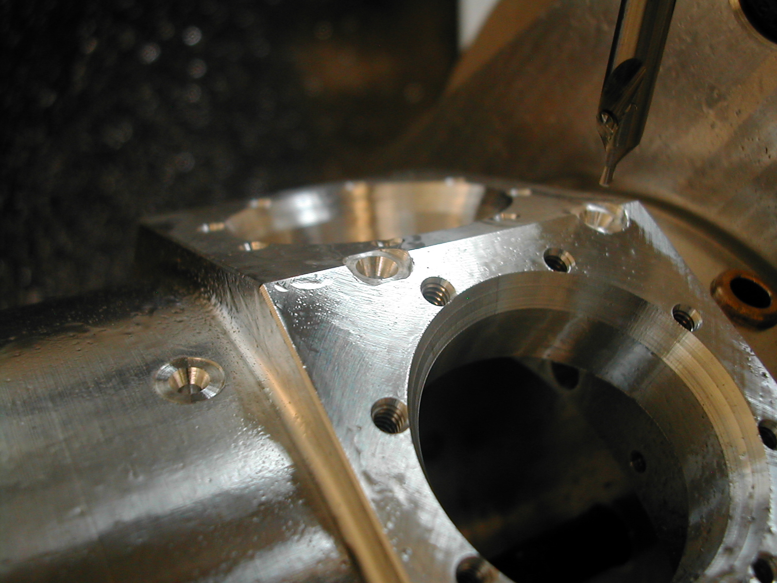
 For the front side of the housing, all of the tappet bushing holes were rough drilled to 0.238″, and then spotfaced with a 8mm end mill to clean up.
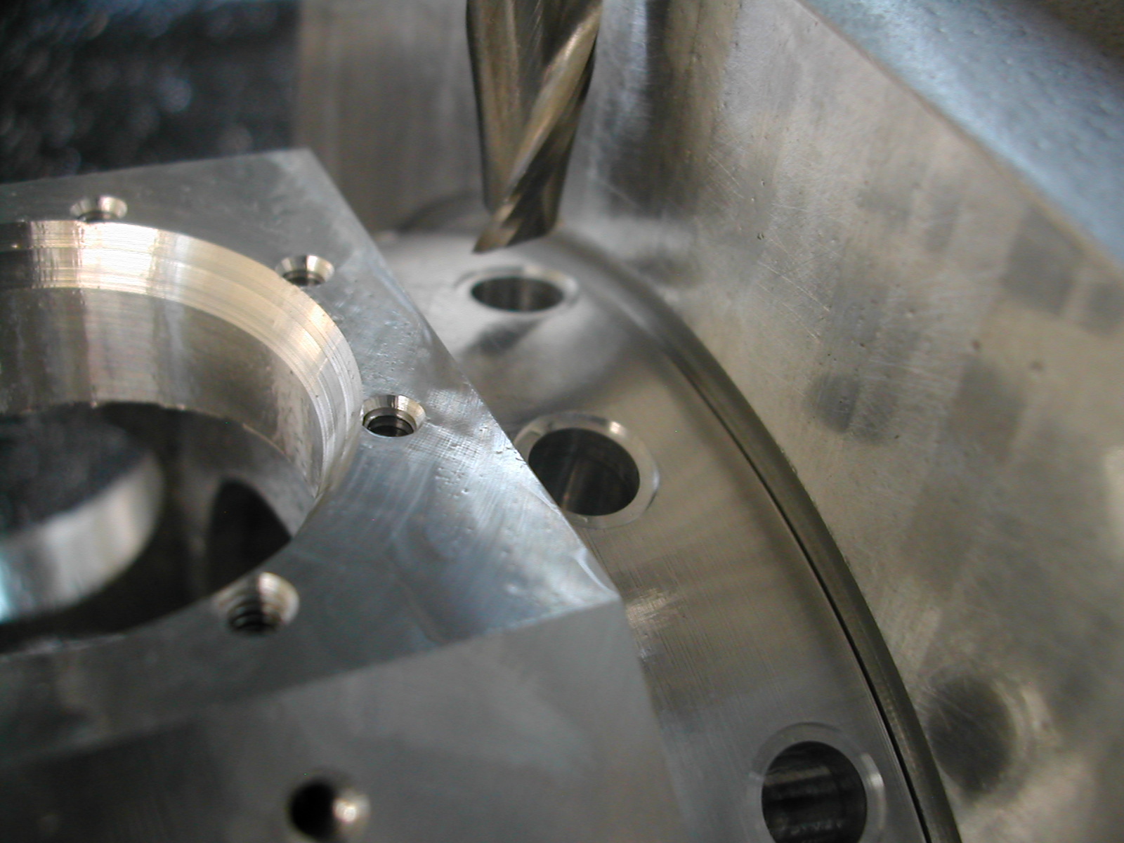
 After spotfacing, the holes were reamed to Ø0.250″.
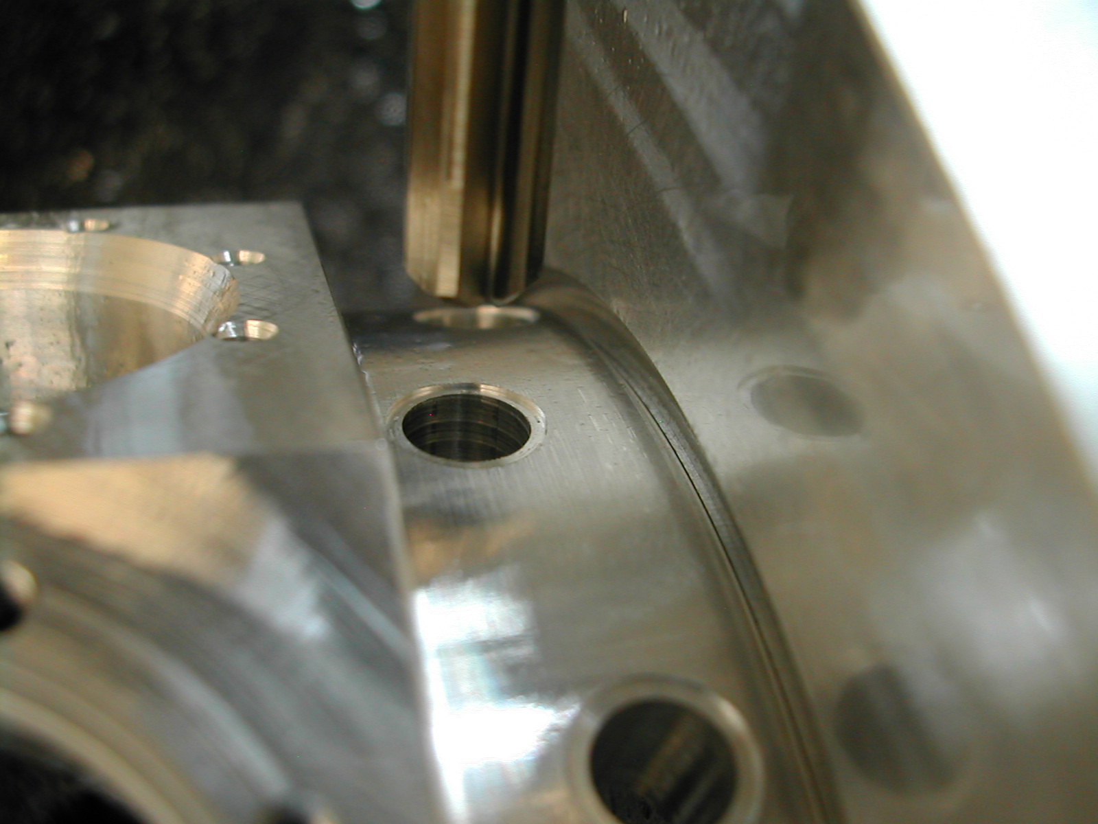
 The bushings were then lightly coated with Loctite 648 and pressed in using a mandrel driven by the mill quill.
 Excess retaining compound was then removed by first blasting with air to force it out of the crevice around the spotface, then washing it off with a spray of acetone.
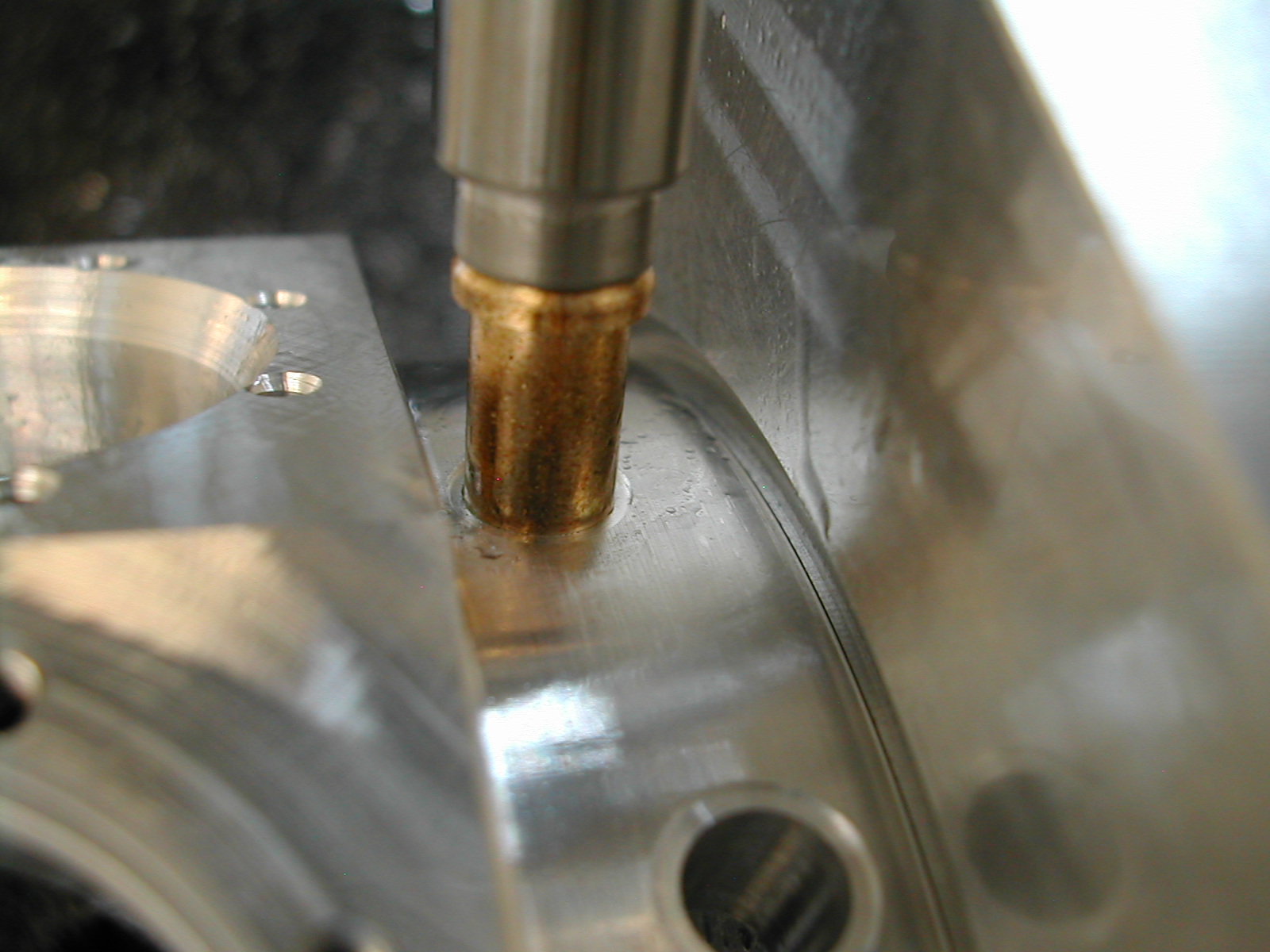
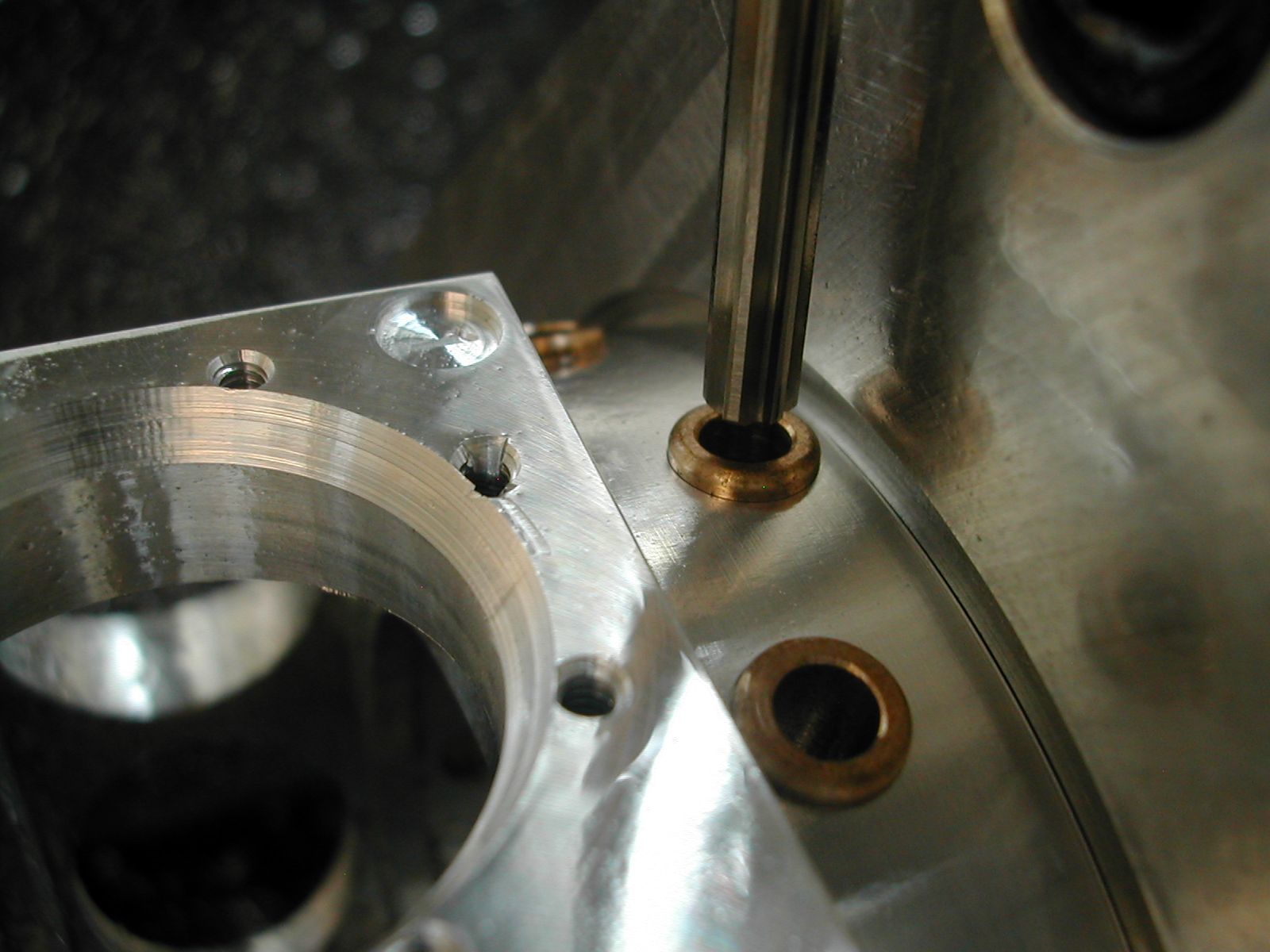 Once the retaining compound was securely set, the bushing were reamed Ø0.251″ for a sliding fit on the dowel pins I used for the tappets.
 On the bottom of the crankcase, the mounting and oil holes for my modified oil sump were next up. The surfaces were spotfaced and then center drilled.
 Followed by drilling, tapping, and reaming, and finally counterboring for the flanges on the sump oil pipes.
 The crankcase is complete except for the two oil pump connector pipes. These will be match drilled with the oil pump housing installed.
The oilpump housing is temporarily assembled to the rear main bearing and both are fastened into the crankcase housing in preparation for drilling the transfer pipe holes.
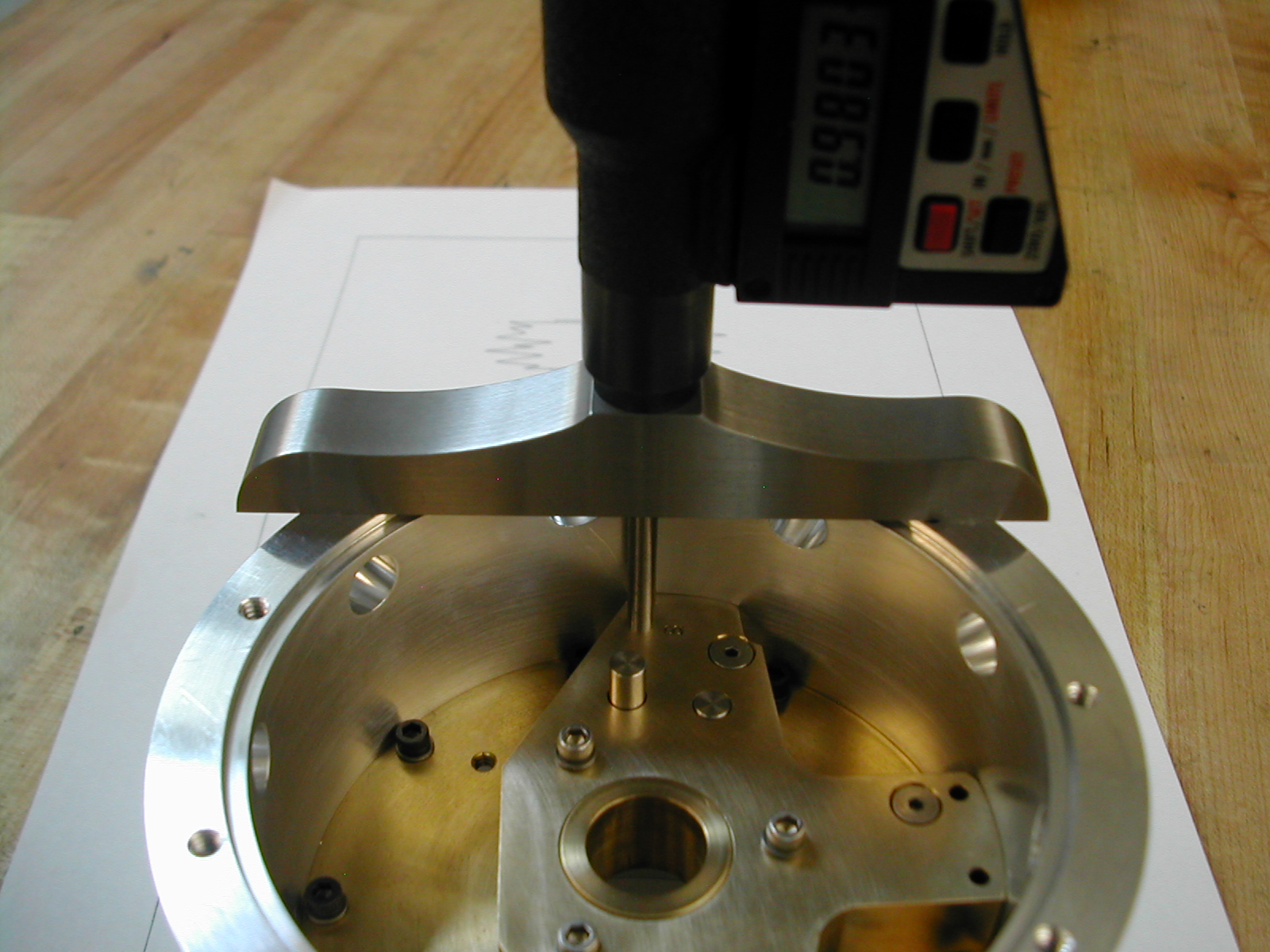 The distance to the top of the oil pump housing as well as the thickness of the housing are recorded so that the transfer pipe holes can be located in the middle of the pump housing.
TO DO
- Match bore transfer line ports.
Disclaimer and License
All material, including the CAD drawings, relating to the construction of the Hodgson Radial presented on this site is free to use any way you see fit. However, no guarantees are made regarding the accuracy or correctness of the material presented here.
Links Used On This Page
(CAD drawings are in AutoCAD 2010 Format)