
 One of the biggest problems with trying to do something like the Hodgson Radial here in China is finding quality materials. I’ve been lucky with my aluminum products since there is a big Alcoa plant in Kunshan not far from where I live that supplies materials for both the China and worldwide aerospace market. Unfortunately I’ve not been as lucky finding a supplier of quality ferrous materials, and the purported 12L14 material I procured for my cylinders is a case in point. While I was assured this material was “equivalent” to 12L14, it was very gummy to machine and did not act at all like a free-machining leaded steel.
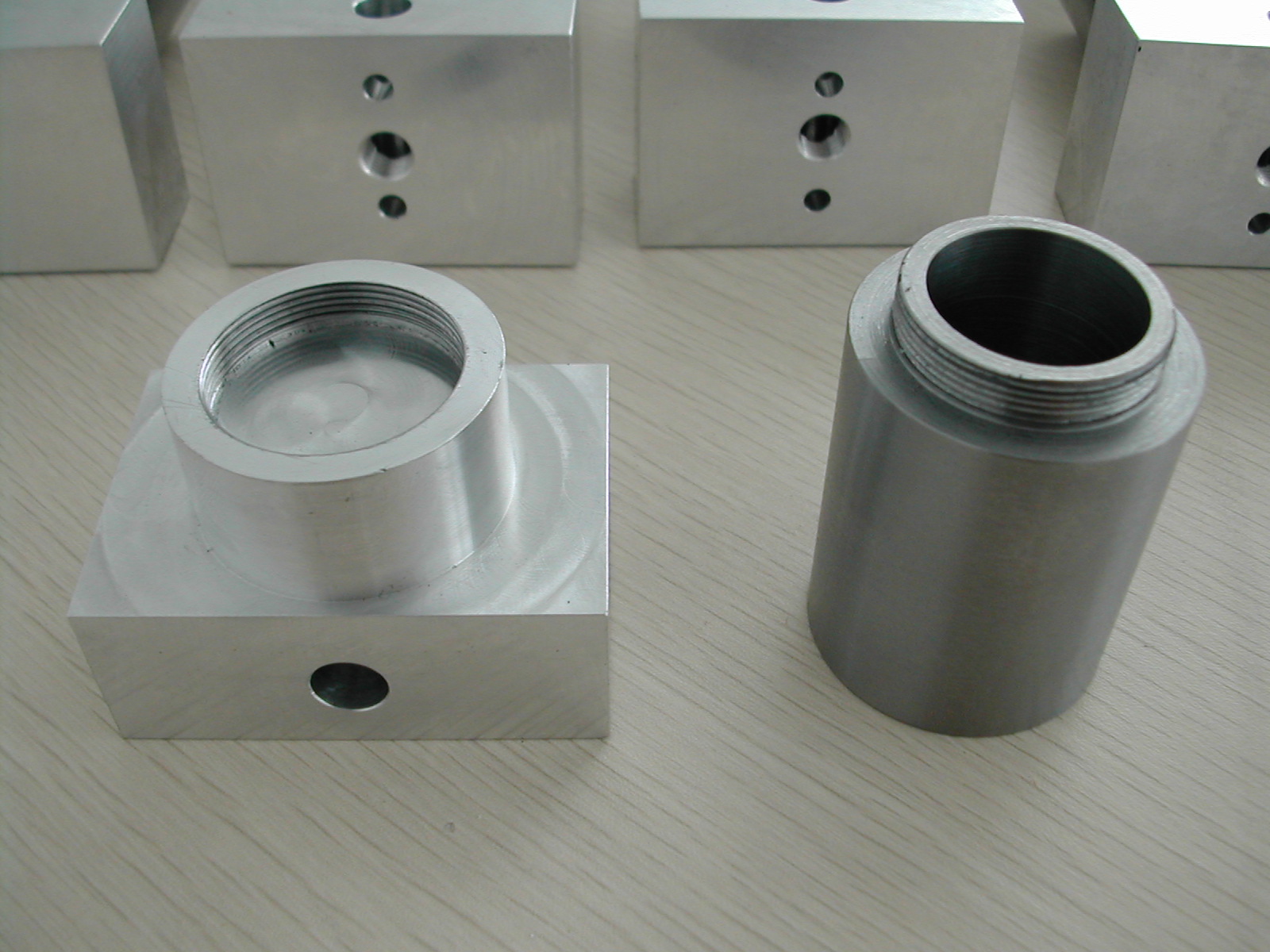 I sawed up 12 slugs of material for the cylinders, faced one end, drilled and bored them to 0.998″, and threaded them at the same time I was threading the cylinder head blanks.
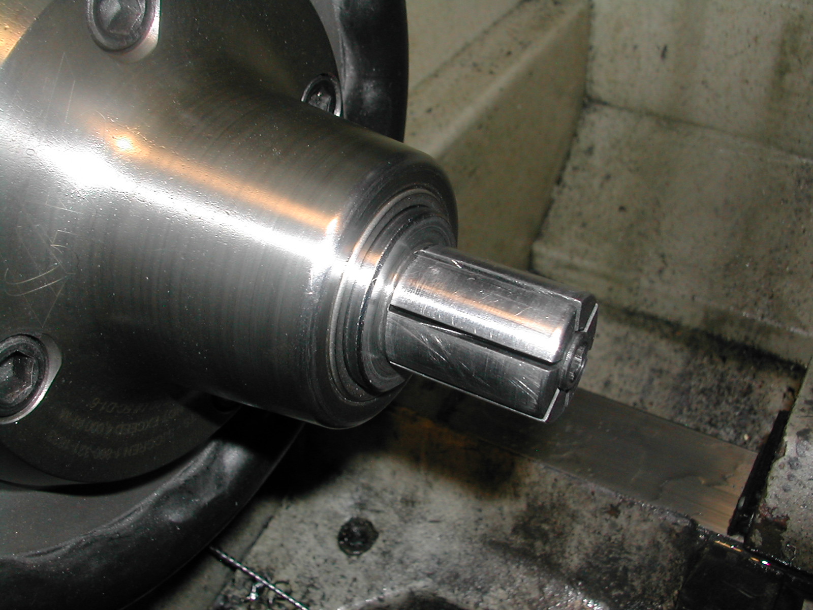 I turned a soft expanding collet to 0.997″ in the lathe. I did this instead of making tool C5 because it allowed access to perform end operations, such as the piston ring chamfer, on the blanks where the nut on tool C5 would have prevented this.
 While the ends of the blanks had been faced before turning the threads, I went ahead and lapped them quickly to insure no burrs would prevent them from seating fully on the expanding collet.
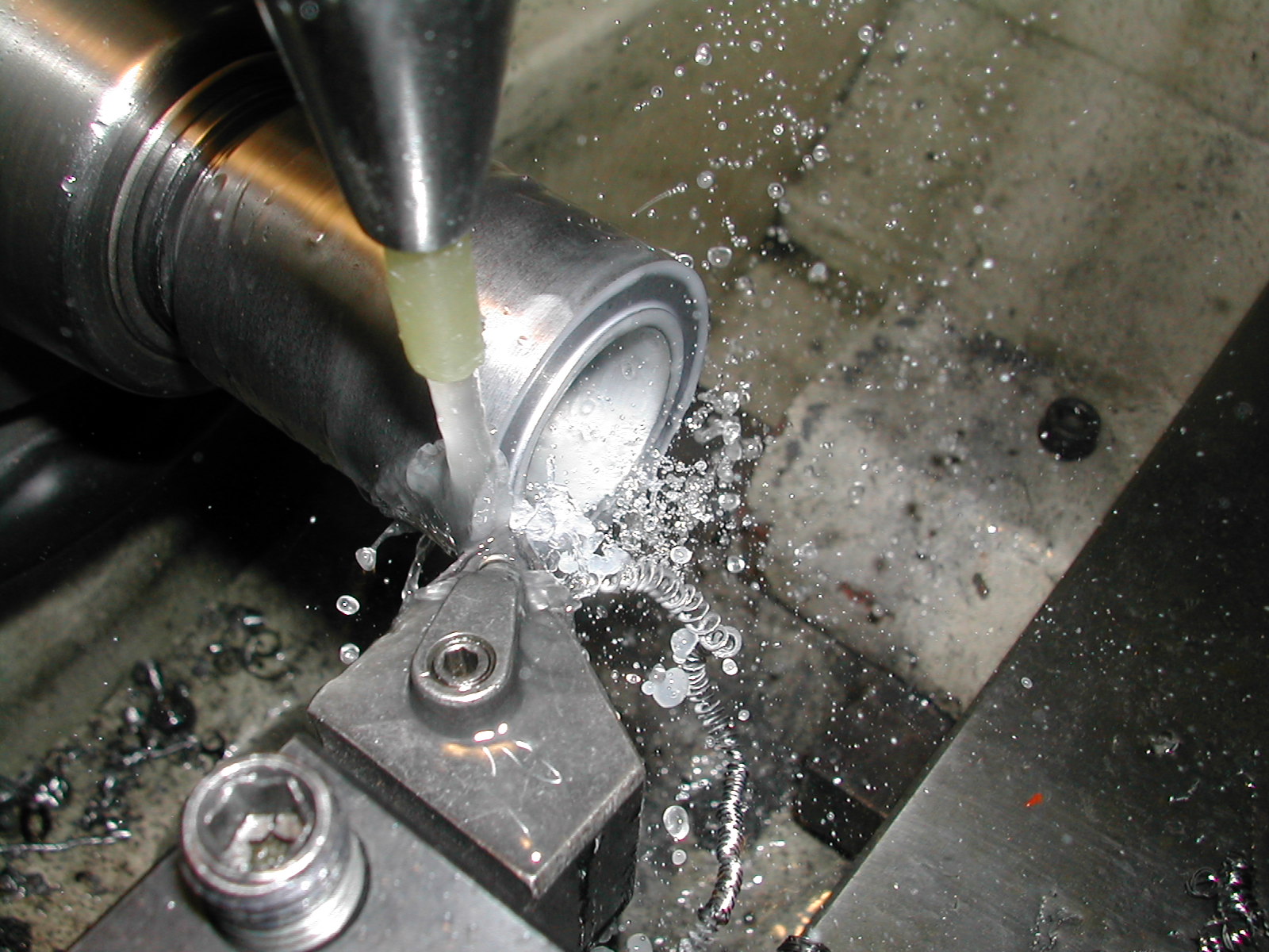 With the threaded head end of the cylinder firmly against the shoulder of the expanding collet, I proceeded to face the cylinder blank to the 2.156″ O.A.L.
It should be noted here that when using expanding collets, or regular collapsing collets, to run multiple parts, it’s important to keep the diameters on the parts consistent. Any variation in the clamping diameter from part to part causes the collet to pull in different amounts. So, in order to keep length variations in check when doing facing operations like this, you need to have consistent diameters.
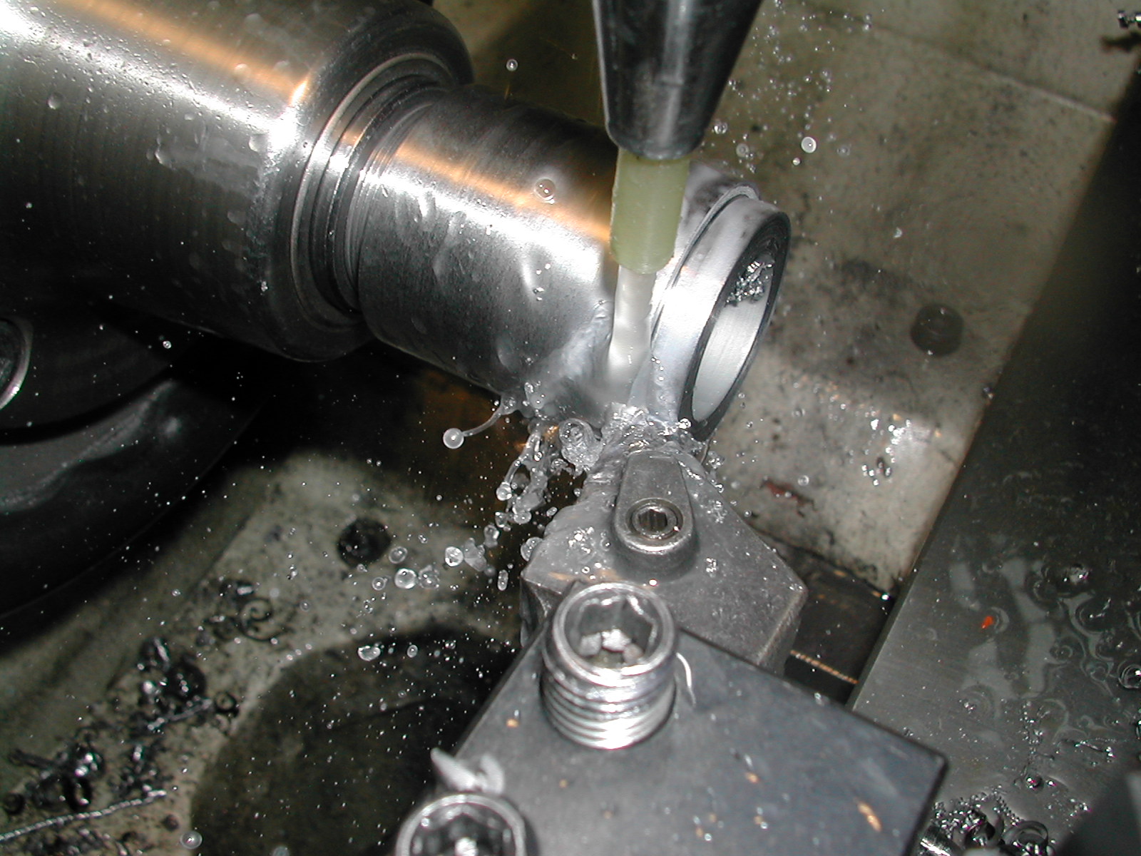 Next I’m turning the 0.656″ long cylinder skirt. The finish diameter of this portion is important so that the finished cylinders will fit properly in the crankcase. Since I have not made my crankcase yet, the actual size is not critical, but it is important to maintain the same diameter on all of the cylinders.
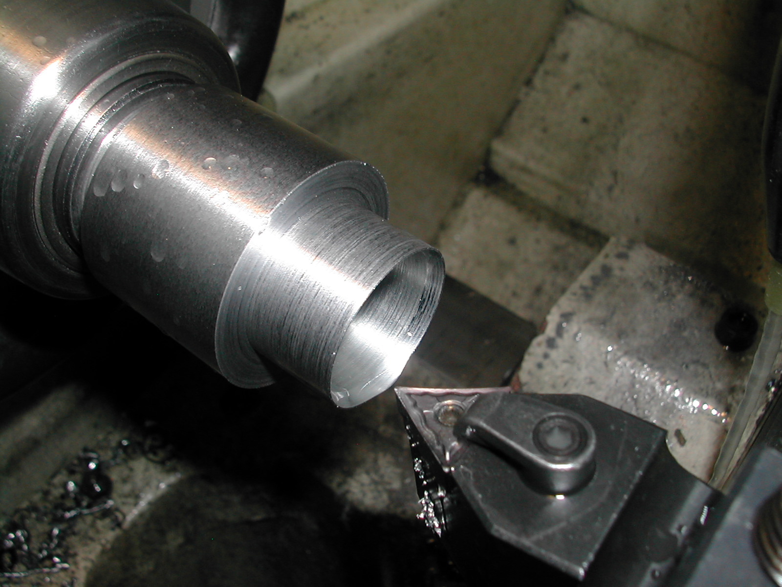 Since my setup and my lathe are fairly rigid, I went ahead and just plunged the 25° chamfer on the skirt end with a 60° insert tool cocked in the toolholder.
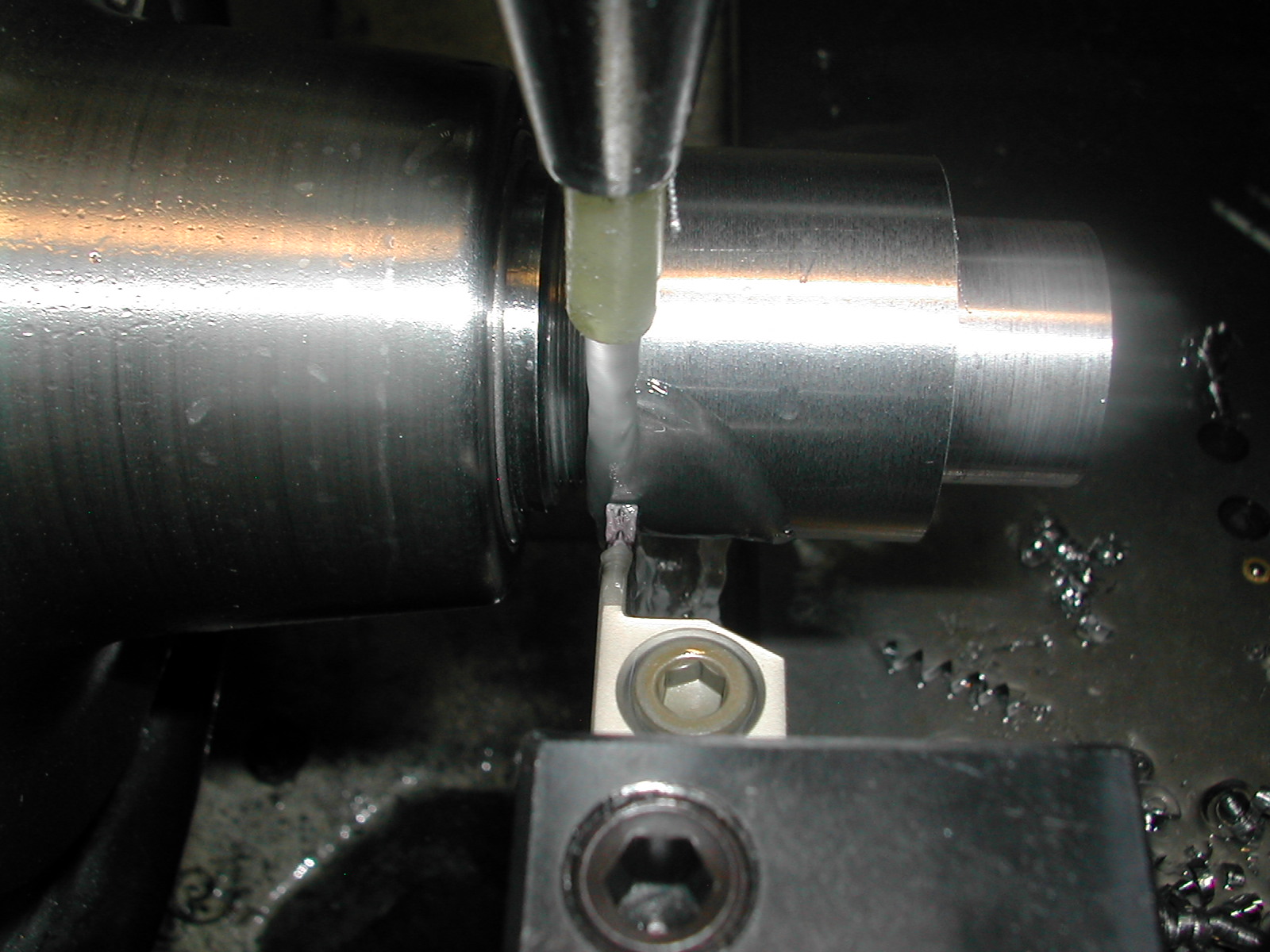 With a 3mm wide insert tool designed for both grooving and profiling, I began to rough out the fin area by plunging to a little over the finish diameter of 1.375″, stepping over 2.5mm and plunging again.
 Here I’ve whittled my way halfway across the fin area.
 Now I’m feeding back across the area I just whittled at the 1.375″ finish diameter.
 The same procedure used for the fin OD is employed again to turn the recess between the fins and skirt. You can see from the poor surface finish how gummy this material was. This is going to take a lot of polishing work to correct later on.
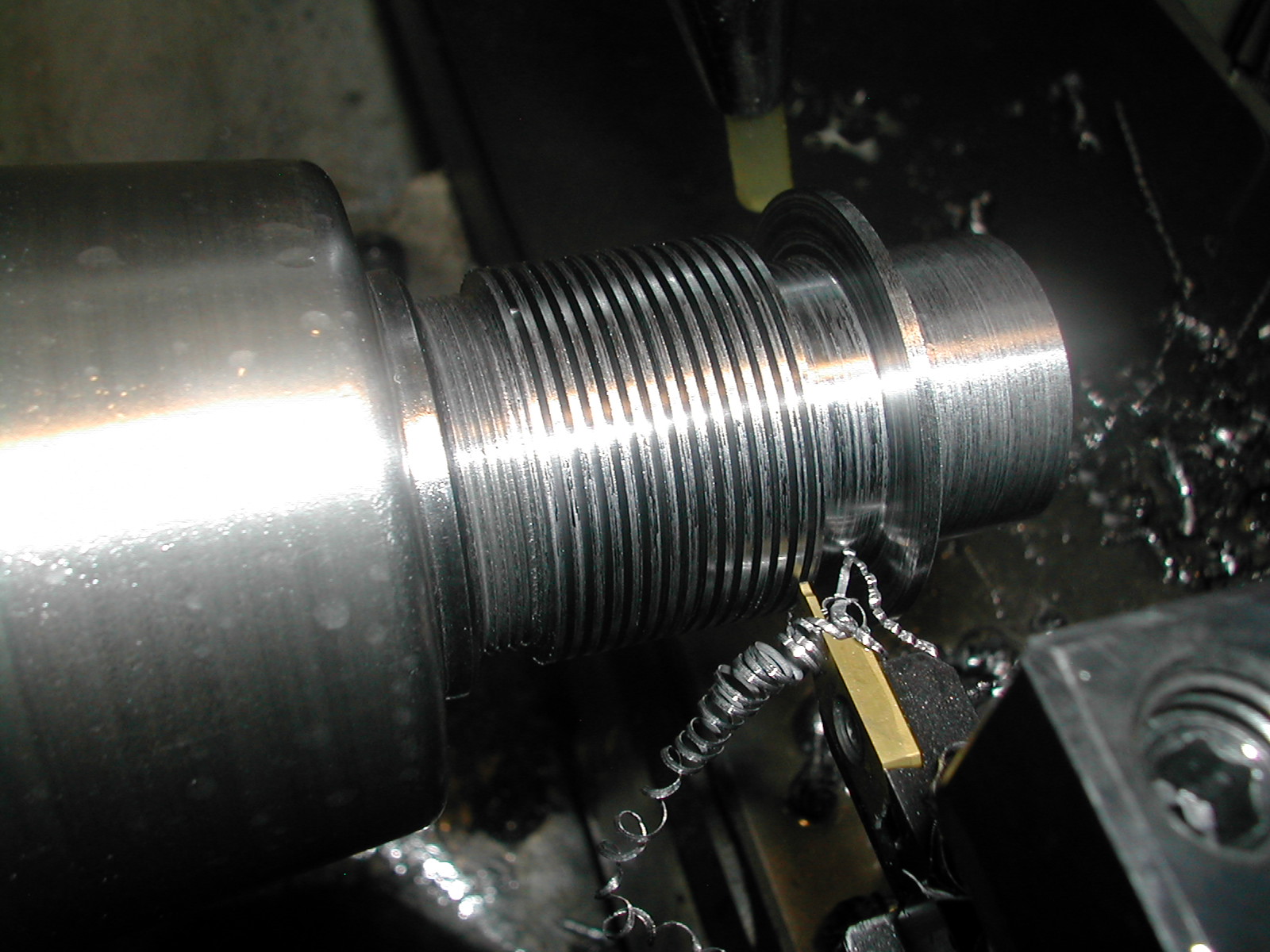
 With the profile of the cylinder complete, it’s time to start on the grooves. I took a 1.0mm wide parting tool and ground it down to the 0.032″ required for the fin slots.
The beauty of using inserts here was that if I broke a tool, I could grind another insert and slap it on without affecting my setup.
 Just past halfway on this set of fins. By this point, I was pretty sure this was not free-machining leaded steel, so I was very concerned with plunging these 0.032″ grooves 0.125″ deep into this mystery material.
Copious quantities of flood coolant kept everything turning smoothly so that one insert was enough to finish all 12 cylinders I was working on.
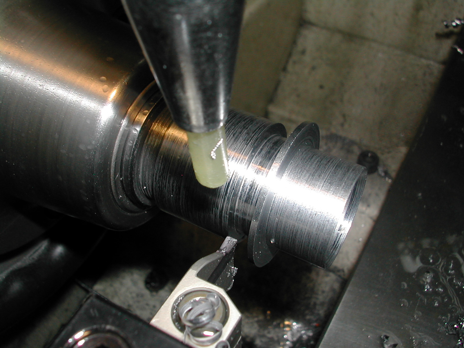
 And here’s the last of the grooves completed. While the surface finish on this material was terrible, the chips produced showed a fairly even cutting action.
 This is the Sandvik SMALR-1010K-3 tool holder with the miniature 1.0mm wide parting insert mounted.
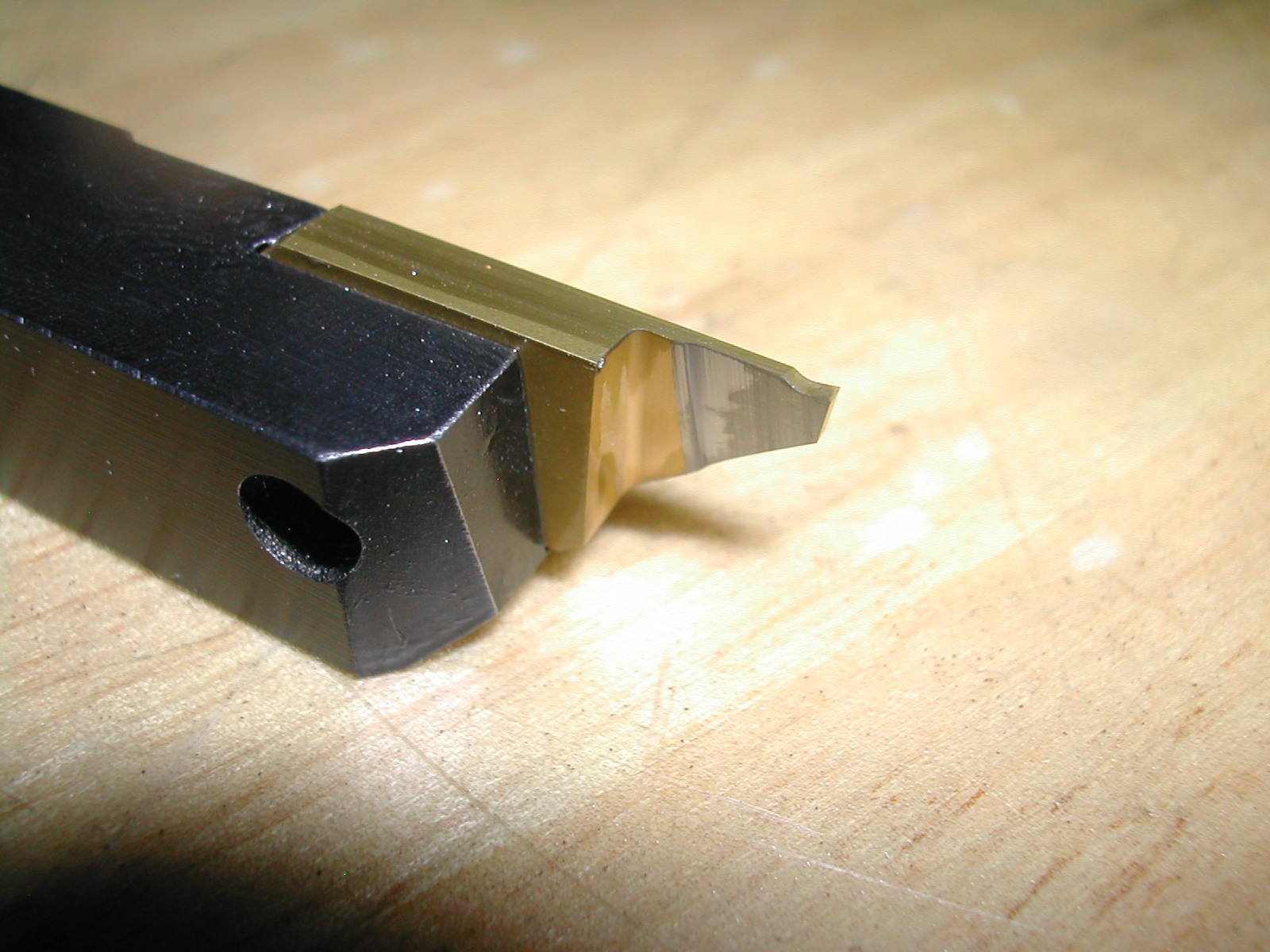 And here is the backside of that same insert where it was ground on a 600 grit diamond wheel down to 0.032″ wide.
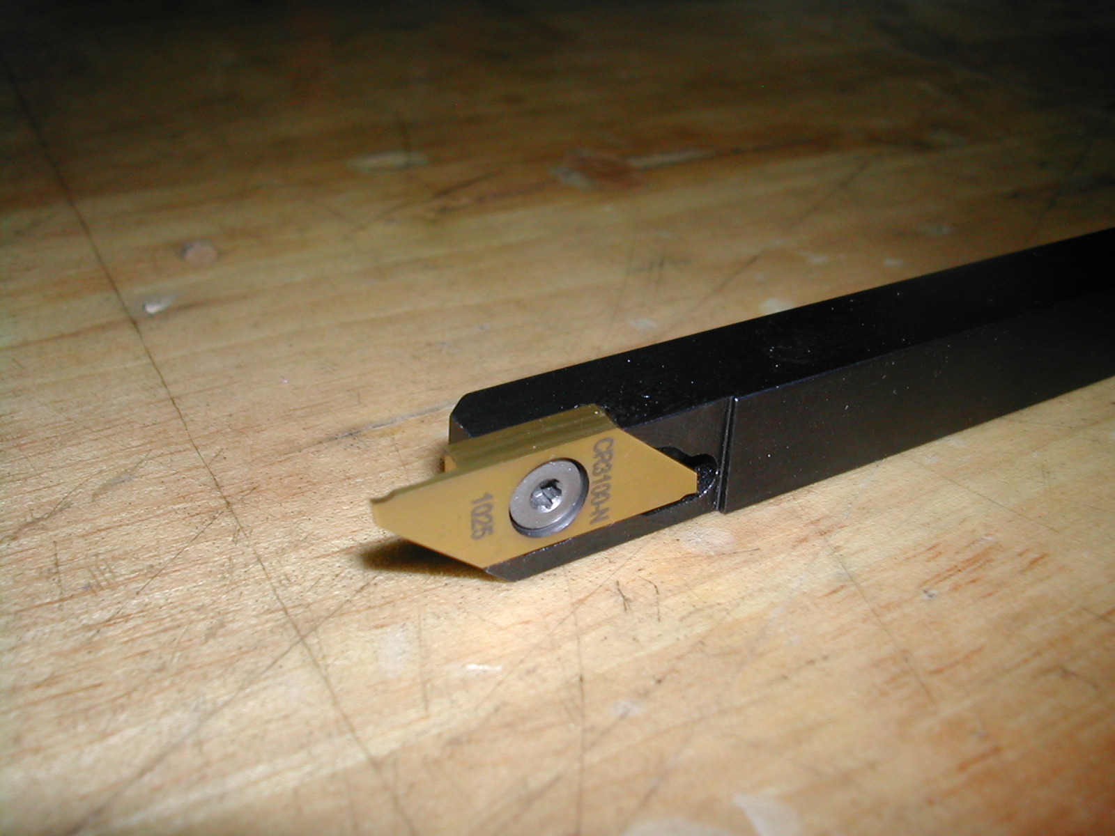
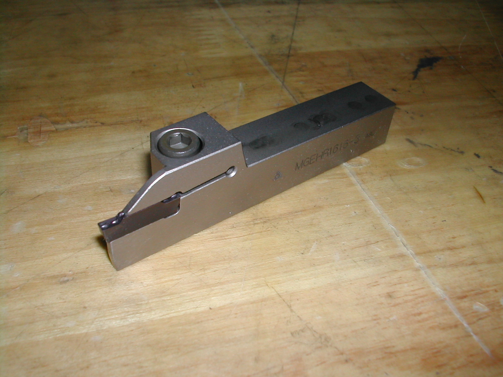 This is a Korloy MEGHR-1616-3 tool holder with a MGMN300-M insert. This profiling insert is 3mm wide with a .2mm corner radius made it easy to work on both left and right-hand faces on this part.
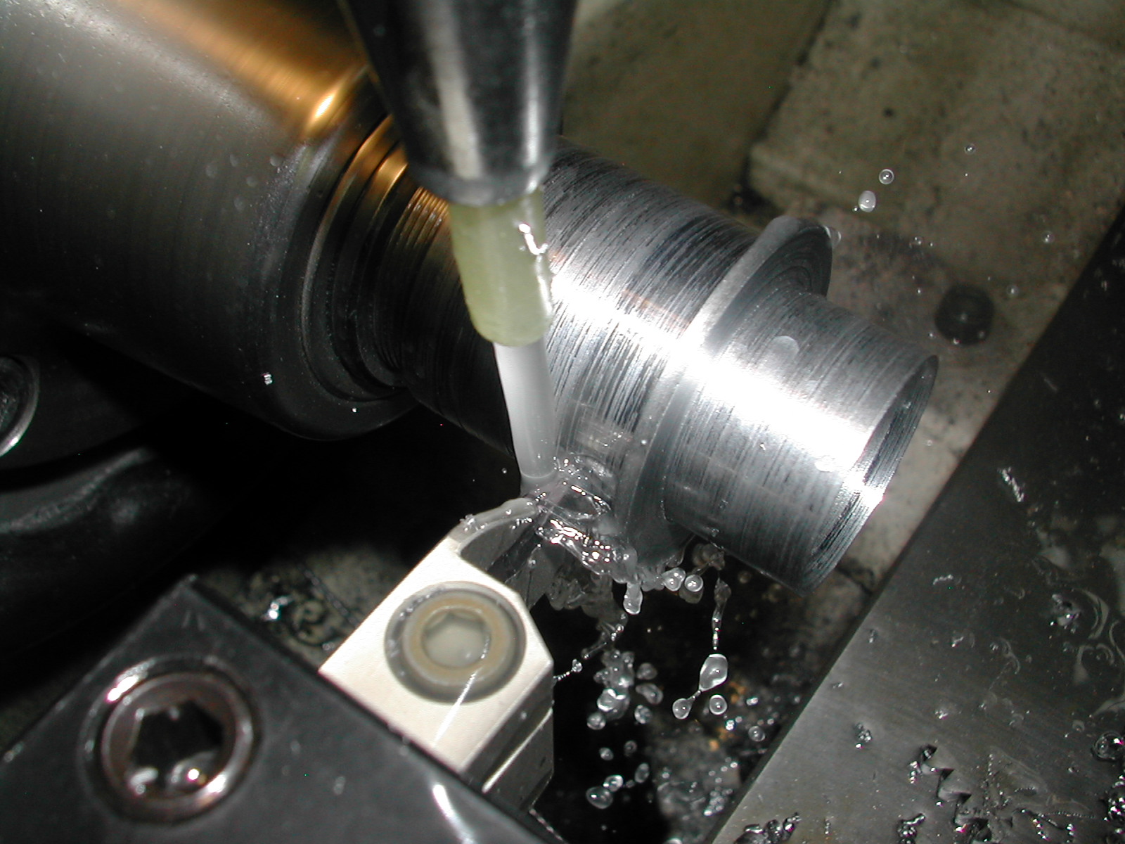
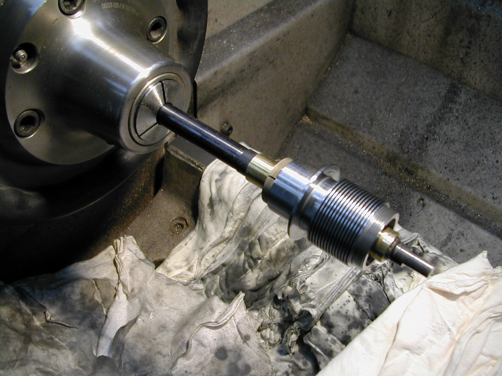 The last step was to remove the 0.002″ stock left on the bore. This was done with some 45µ paste and lots of oil.
 The lathe bed was protected with shop towels, and the part was lapped by hand. With the lathe running at 600rpm, it took about 20 minutes and 3-4 charges to lap each cylinder to size. All of the cylinders were lapped to 1.0000″±0.0002″.
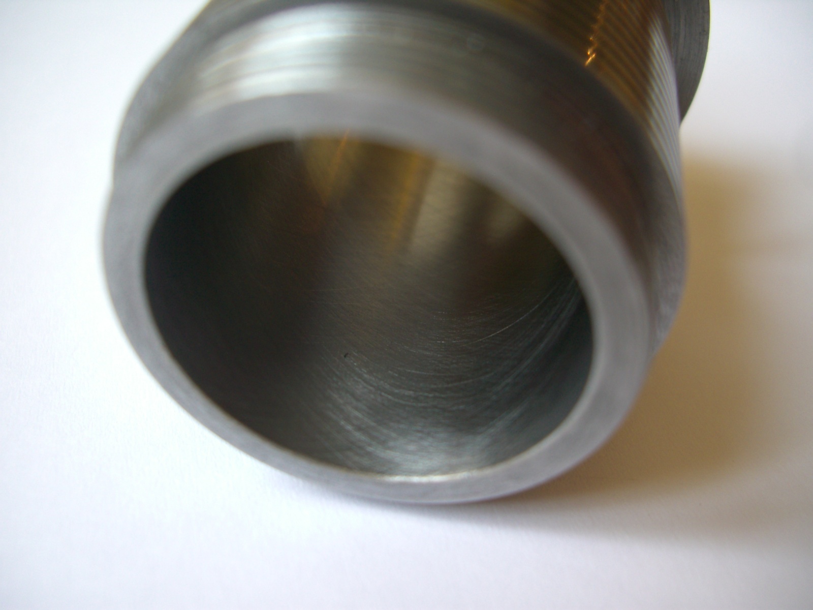 Once I got the hang of it, I was able to leave a nice 30° crosshatch in the bore.
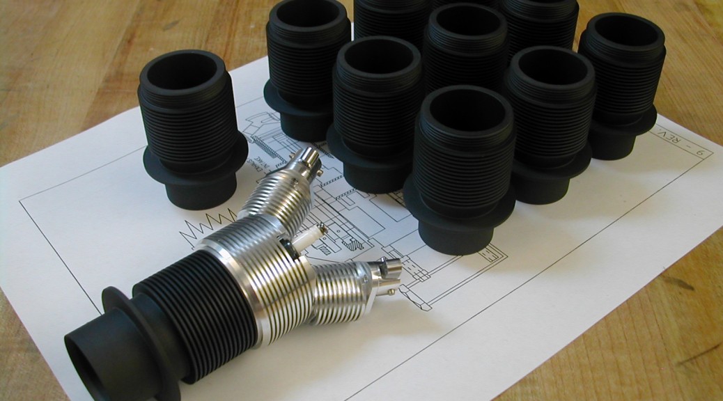
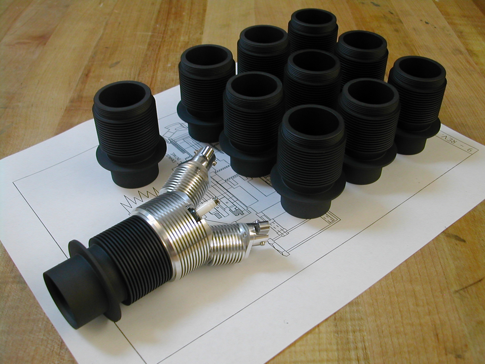
Manganese Phosphate (Parkerizing) treatment performed on all of the cylinders. I ask for no sandblasting, so guess what I end up with? At least they didn’t blast the bores too badly.
TO DO
- Fit to heads
- Drill aprons
Disclaimer and License
All material, including the CAD drawings, relating to the construction of the Hodgson Radial presented on this site is free to use any way you see fit. However, no guarantees are made regarding the accuracy or correctness of the material presented here.