
 This page is one of the longest in the Hodgson Radial log and probably reflects that this is one of the most complex parts. I chose Aluminum 7075-T651 for the head material and made a few changes to the process plan and the design of the head – most notably the method of retaining the valve seats. Follow along on this lengthy build log as I start construction of 11 heads.
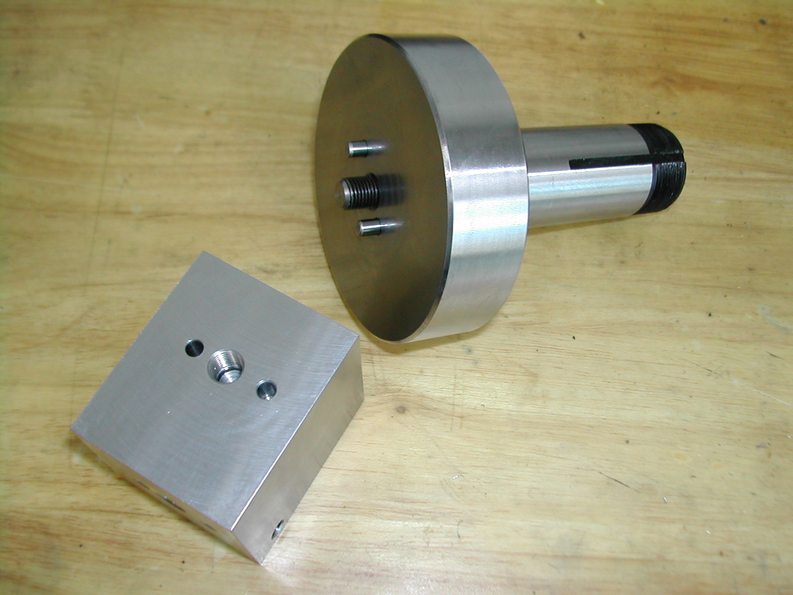 First off was the construction of tool CH2. Instead of affixing this tool to a faceplate in the lathe, I have chosen to use a 5C “pot chuck”. This photo shows the pot chuck and the steel blank for tool CH2.
You can also see from this image were I’ve added two 3/16″ dowel pins to act as registration pins and drive dogs – not wishing to rely on the 3/8″-24 bolt to do either of these tasks. The pins are asymmetrical around the central threaded hole forcing the tool and the later head blanks to only mount one way. It was hoped this, along with the key in the 5C chuck would help insure concentricity as the parts were removed and remounted.
 Here’s the setup in the lathe with the blank for tool CH2 mounted. The pot chuck is removed from the 5C chuck to access the 3/8″-24 SHCS securing the part.
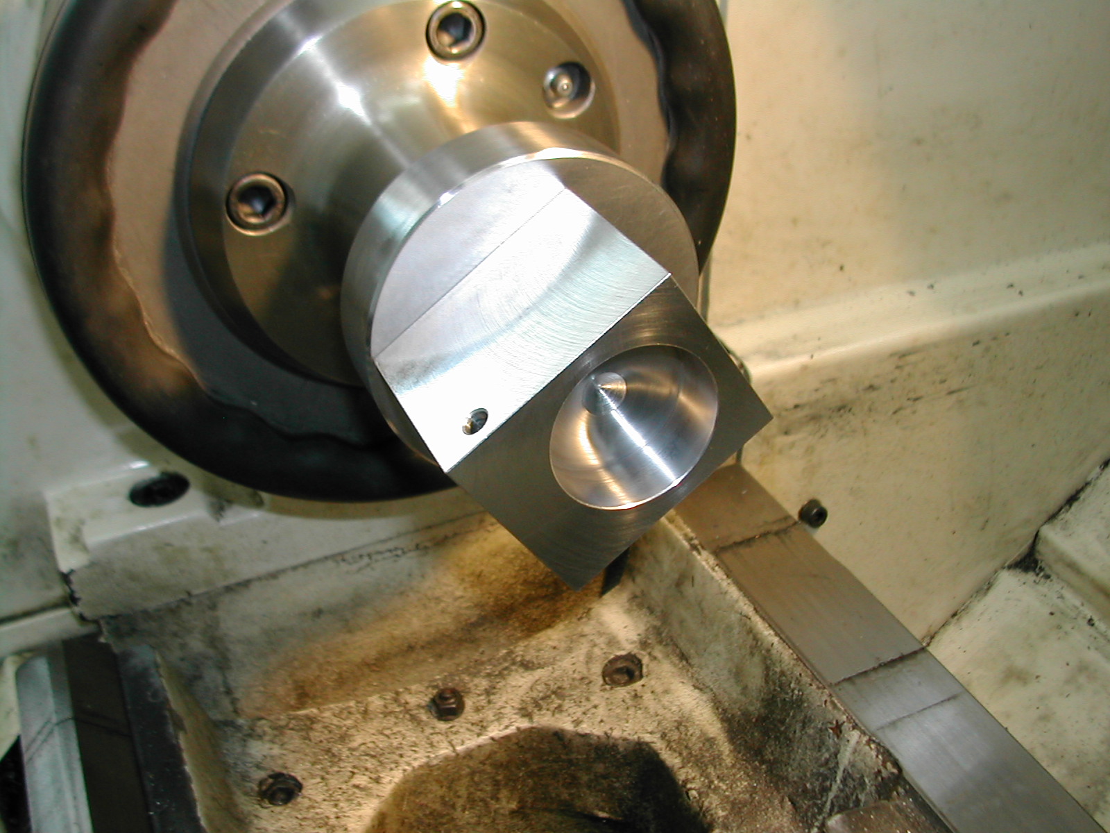 The 1.564″ bore has been drilled and bored to finish size. not much lathe work on this tool so we’ll head back to the mill to finish it up.
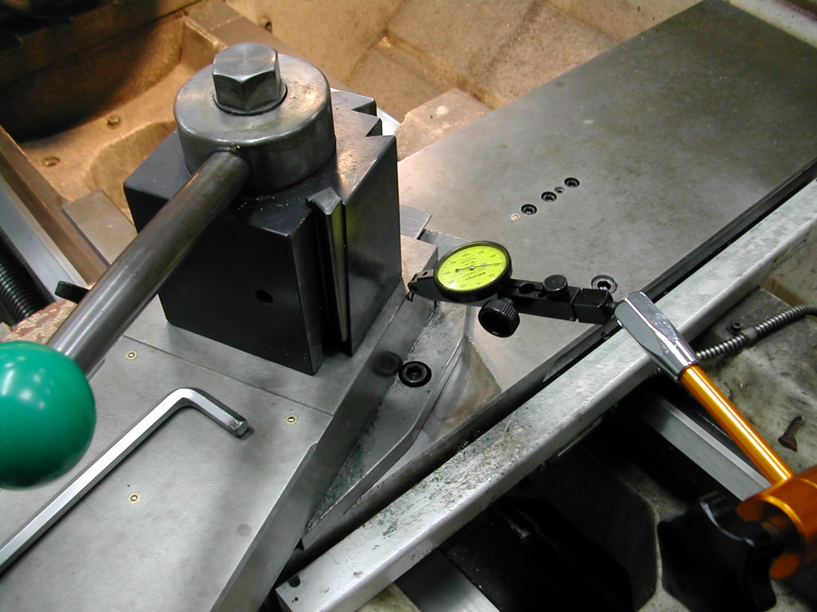
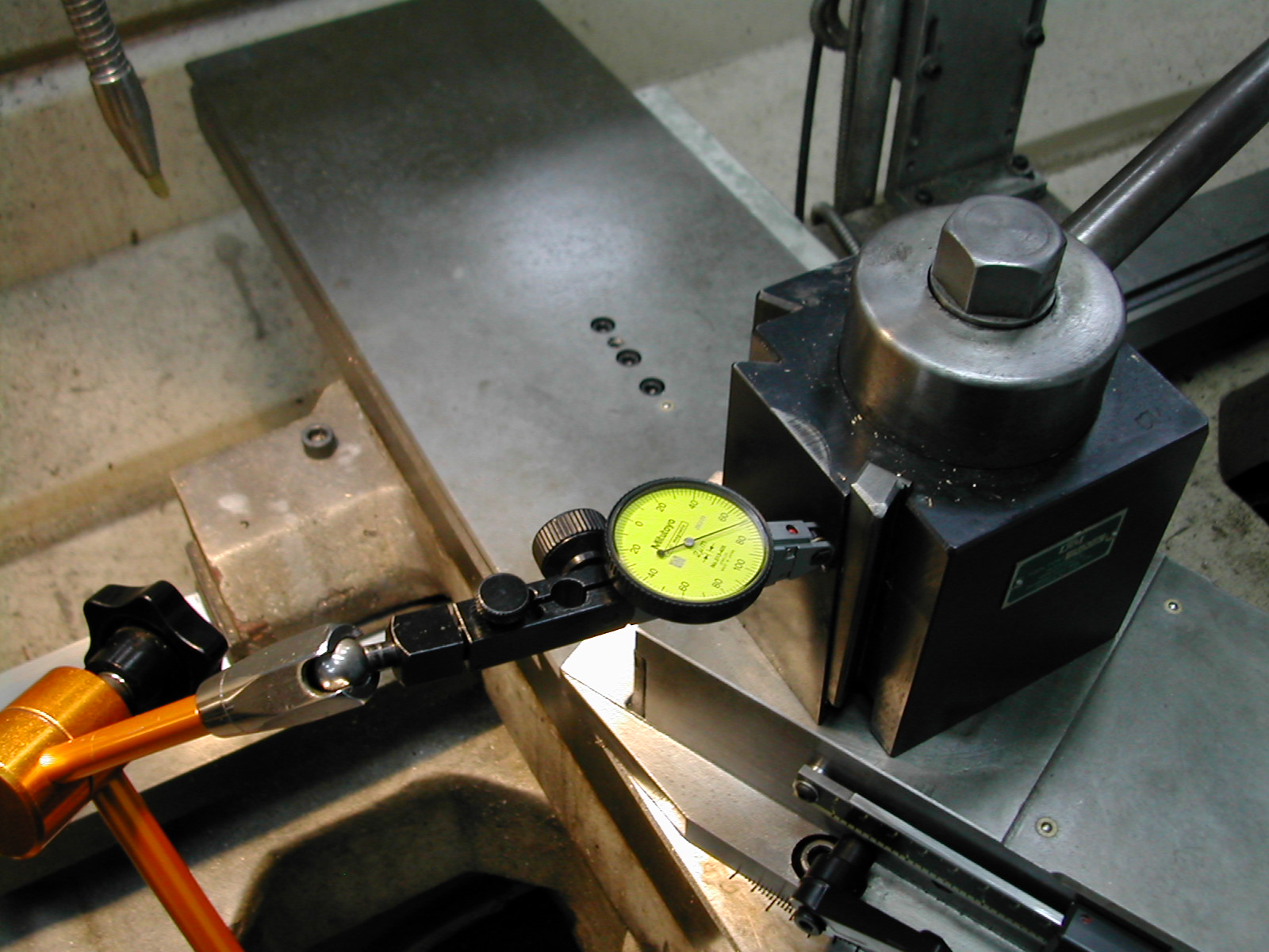
 Milling the 25° angle was a critical operation. I used a dial indicator, some trig, and the DRO, to get the blocked clamped as close to 25° as possible since many future operations depend on this angle.
A dial indicator was chucked in the quill, and the part was clamped at approximately 25° using my combination square’s adjustable head. The quill was lowered to just touch the indicator to the blocks surface. The mills X axis was then moved so the indicator was near the other edge of the block and the knee was then raised to return the dial indicator to it’s previous reading. The arctan of the DRO’s X and Z values was then checked to see how close to 25.0° I was. After adjusting the blocks position a few times and repeating the above, I called it quits at 25.02°.
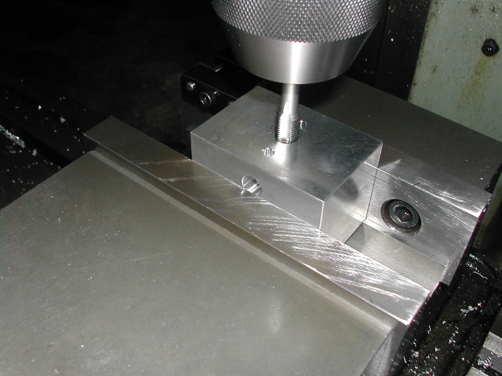 With tool CH2 complete, I began preparing the eleven 7075-T6 head blanks. After squaring the stock to 1.75″x1.75″x2.50″, the 0.375″ cross hole was drilled and reamed. This was followed by drilling and reaming the drive pin holes and then drilling and tapping the central hole for the clamp bolt.
 Here are the 11 blanks waiting to be turned into heads. Before starting the lathe work, I roughed out the lower part of the heads using the rotary table on the mill. I rotary milled the O.D. to 1.6″ in diameter and to the finished 0.762″ depth (drawing shows 0.764″). While the blanks were still on the rotary table I also rough milled the thread pocket to 1.190″ diameter and to the finished 0.250 depth.
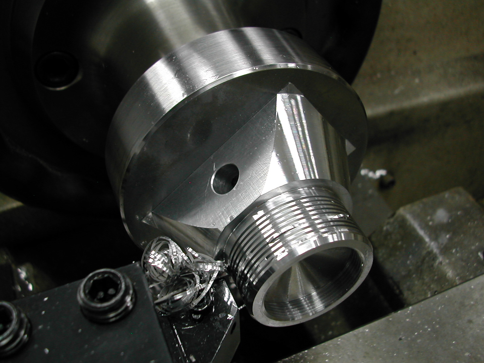
 Over at the lathe, I went ahead and put the internal 1.250″-24 thread on all of the head blanks. I took a little time out on the heads to go ahead and rough-out and thread the cylinders blanks as well.
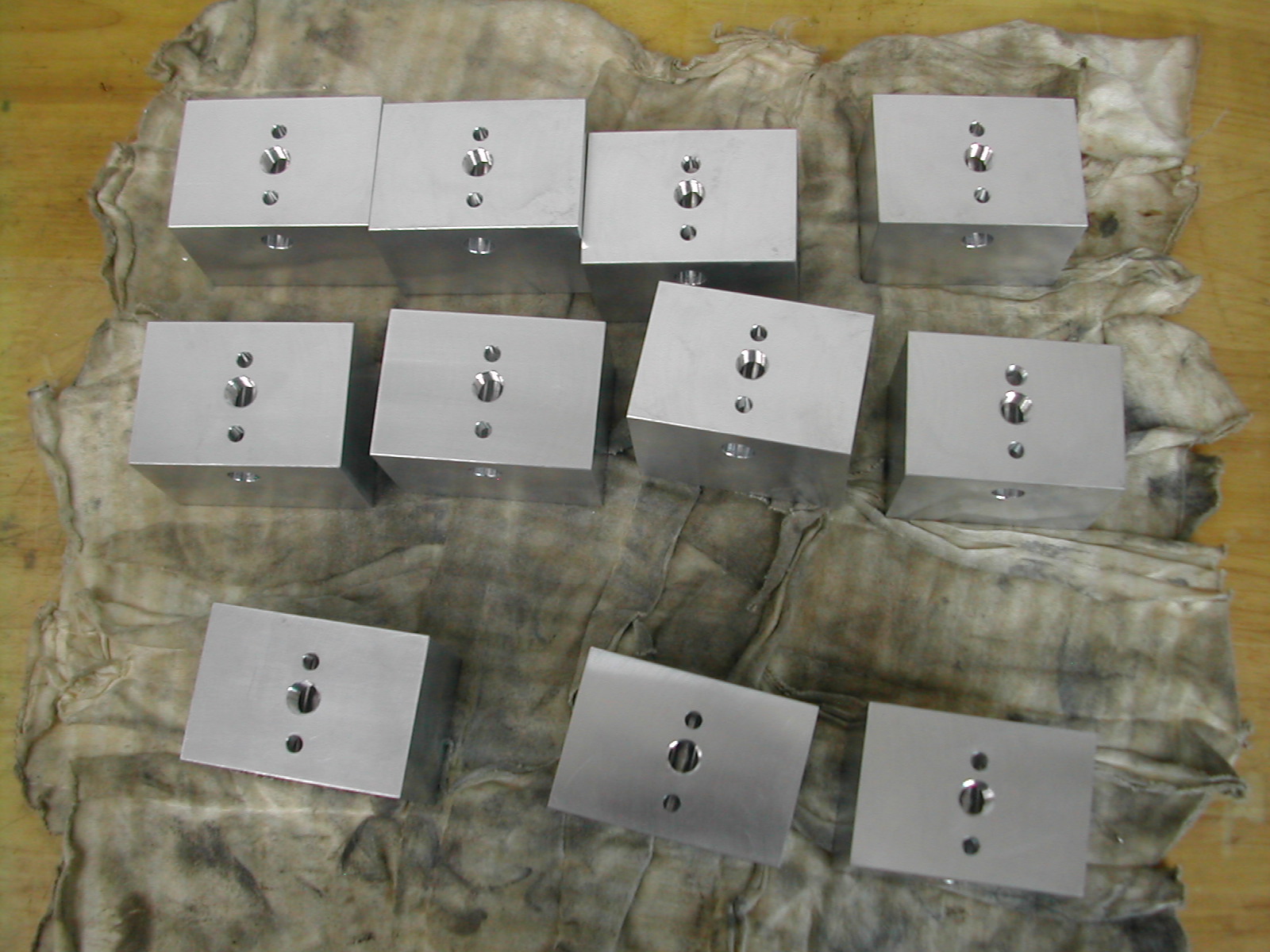
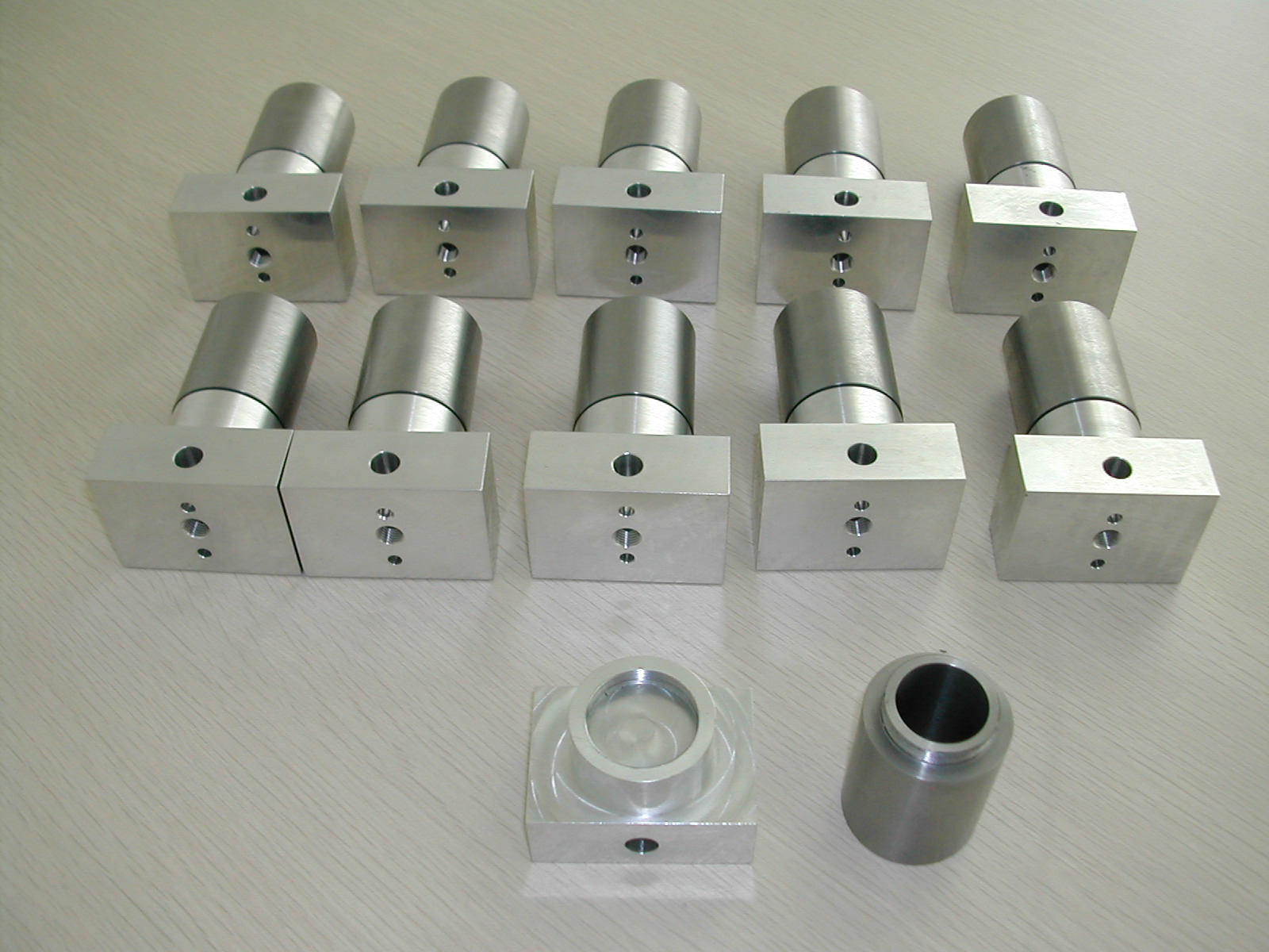 Here’s my 11 head and cylinder blanks. I’m making 9 sets for the engine, with one extra set-up part and one extra set for a cut-away display to be made later.
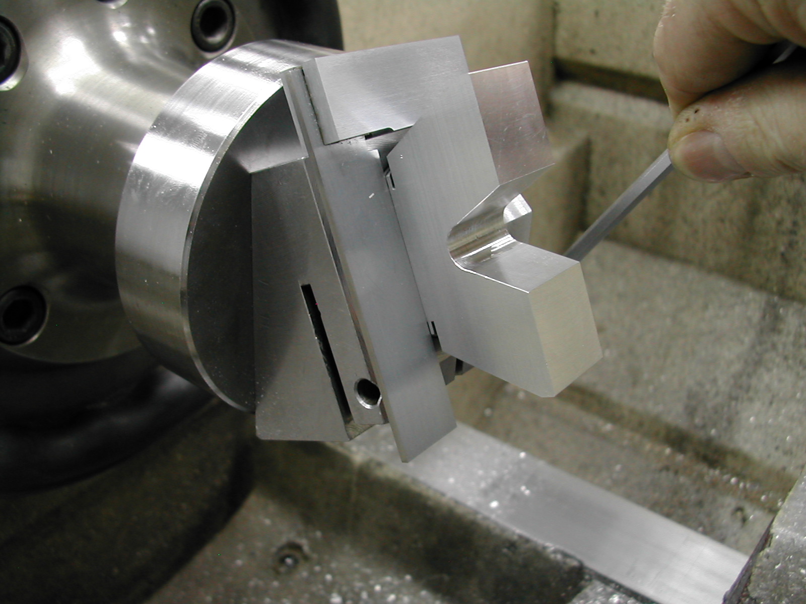
 The next setup in the lathe is to create the combustion chambers. I’m again using a dial indicator along with the DRO to accurately set the crossslide to 25°. I’ve made a “D”-bit to create the actual conical combustion chamber, but I’ll need to use the crossslide to blend in the thread relief.
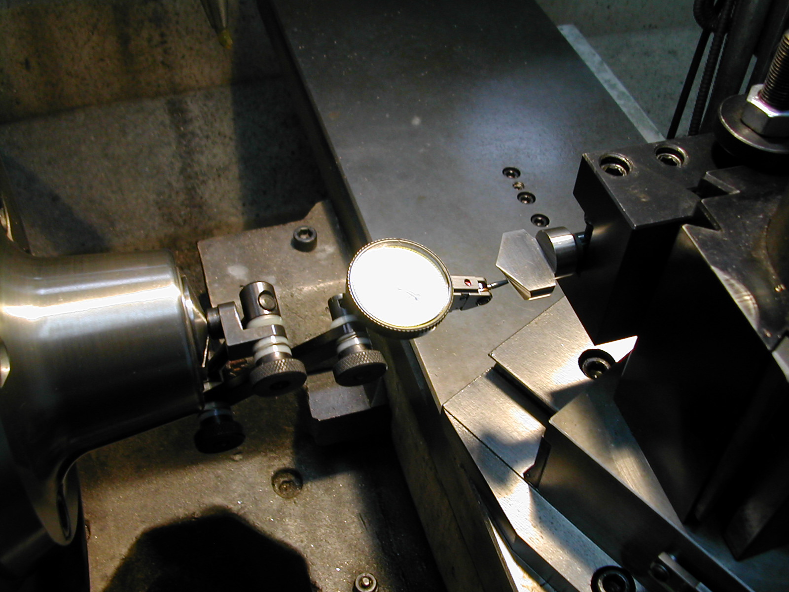
 With the crossslide locked in at 25°, the next step is to insure my toolpost is orthogonal with the lathe axis.
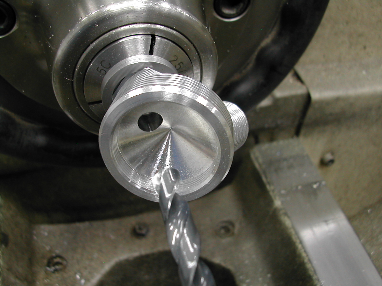
 Now it’s time to begin presetting my tooling. I’ve mounted my “D”-bit in a toolholder instead of a drill chuck in the tailstock so that I can accurately control the depth of the combustion chamber.
Variations in the combustion chamber depth will mean I’ll have to do individual setups later on when installing the valve seats and I don’t want to do that. I’m using my dial indicator here to center the “D”-bit with the spindle’s axis both in height and in X.
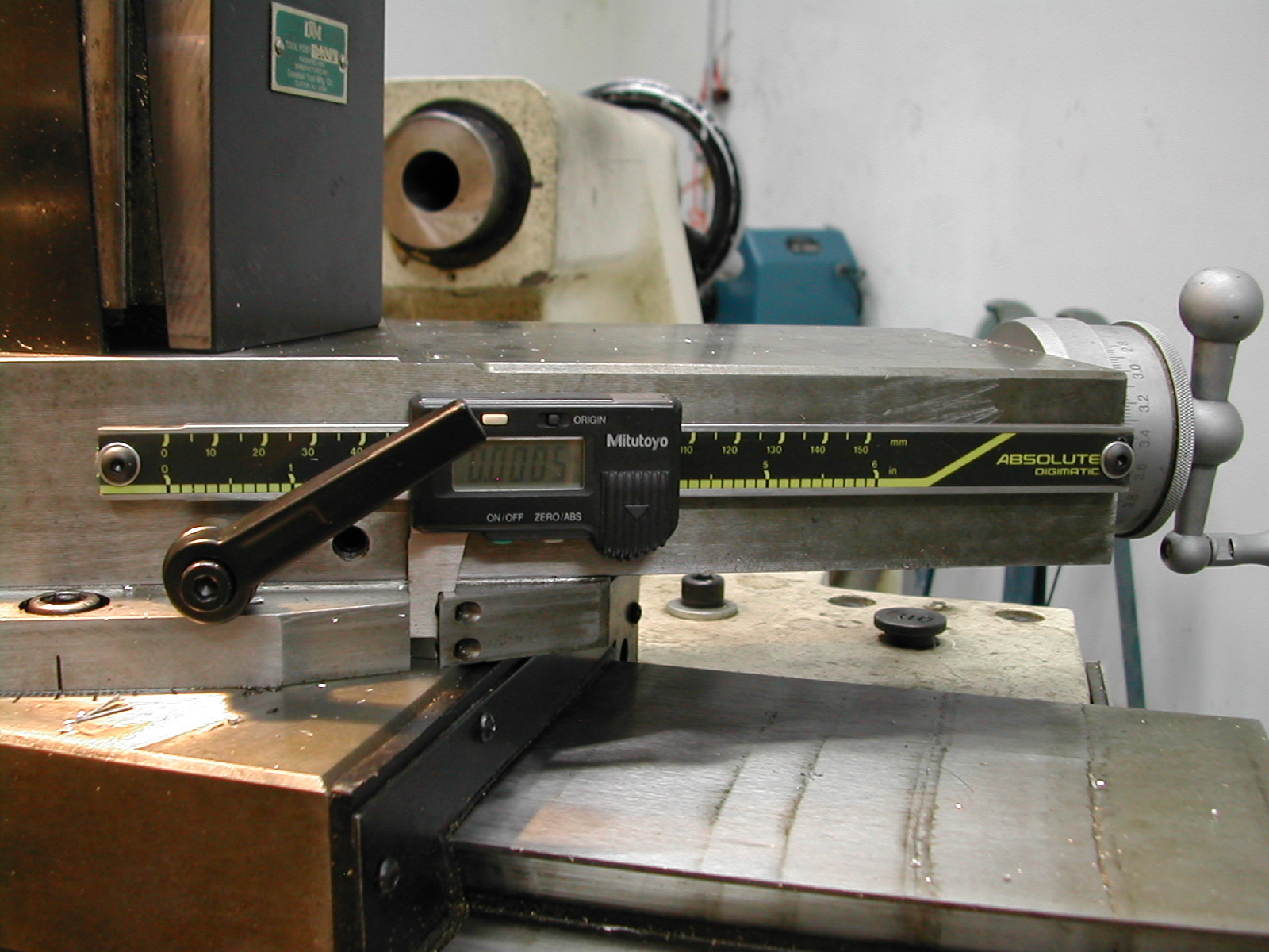 I had previously equipped my crossslide with a digital readout made from an old caliper whose jaws had become worn. This will make it very easy to zero my tools when blending the thread relief. The crossslide dial is graduated but it’s in metric. Being able to switch between metric and inch units as well as set arbitrary zero points makes this a very nice addition.
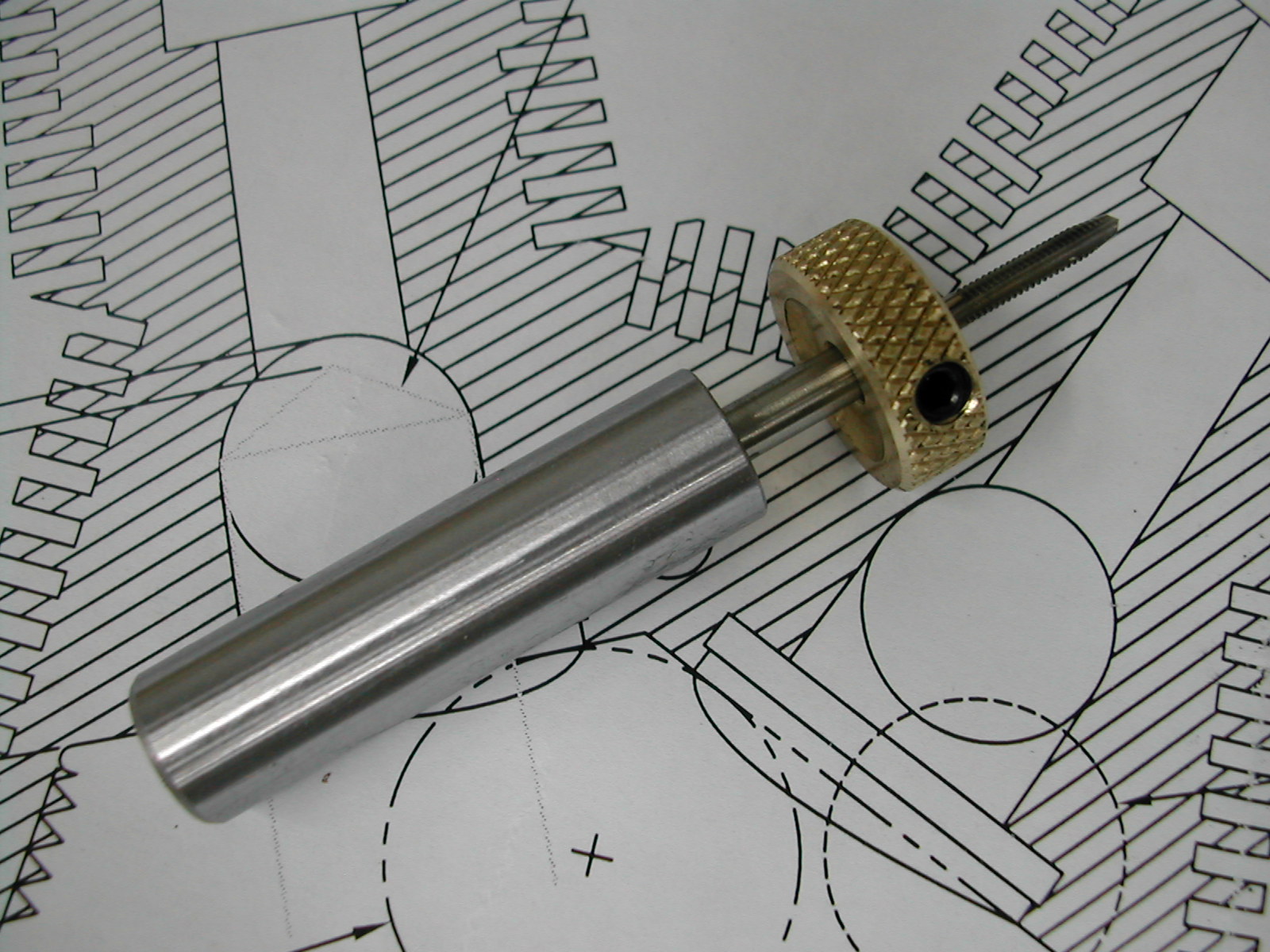
 Here’s a better shot of my “D”-bit I made to generate the conical combustion chamber. This could have been easily made from some O-1 or A-1 toolsteel, but I happened to have an old 32mm single lip countersink that was past it’s prime. First I ground the O.D. down to 1.200″, then split the end down to center removing the old single flute at the same time. Next, I ground a 130° included angle on the countersink. I mounted the c’sink in a 5C collet block in the mill and used the indicator/DRO method to check the angle as I progressed.
Once I had the correct angle, all that was left to do was to relieve the cutting edge.
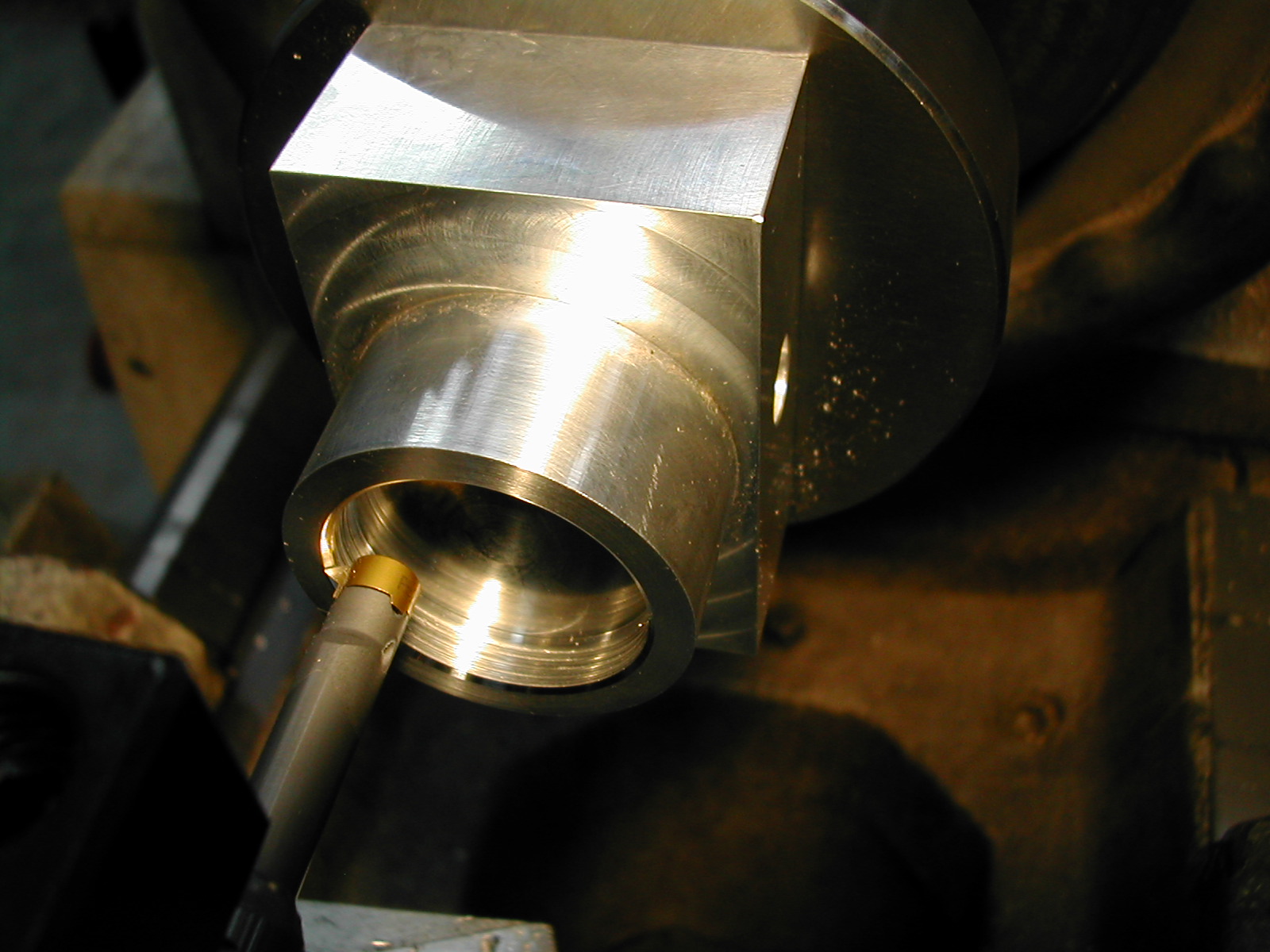
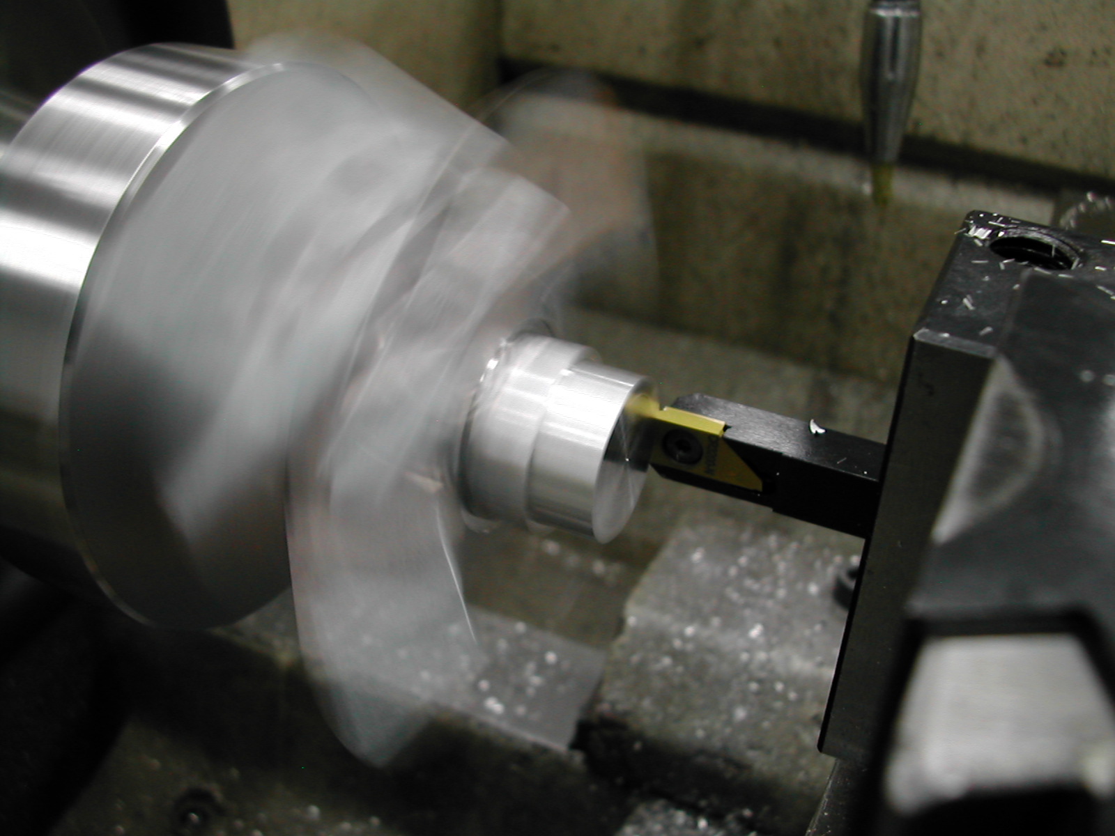
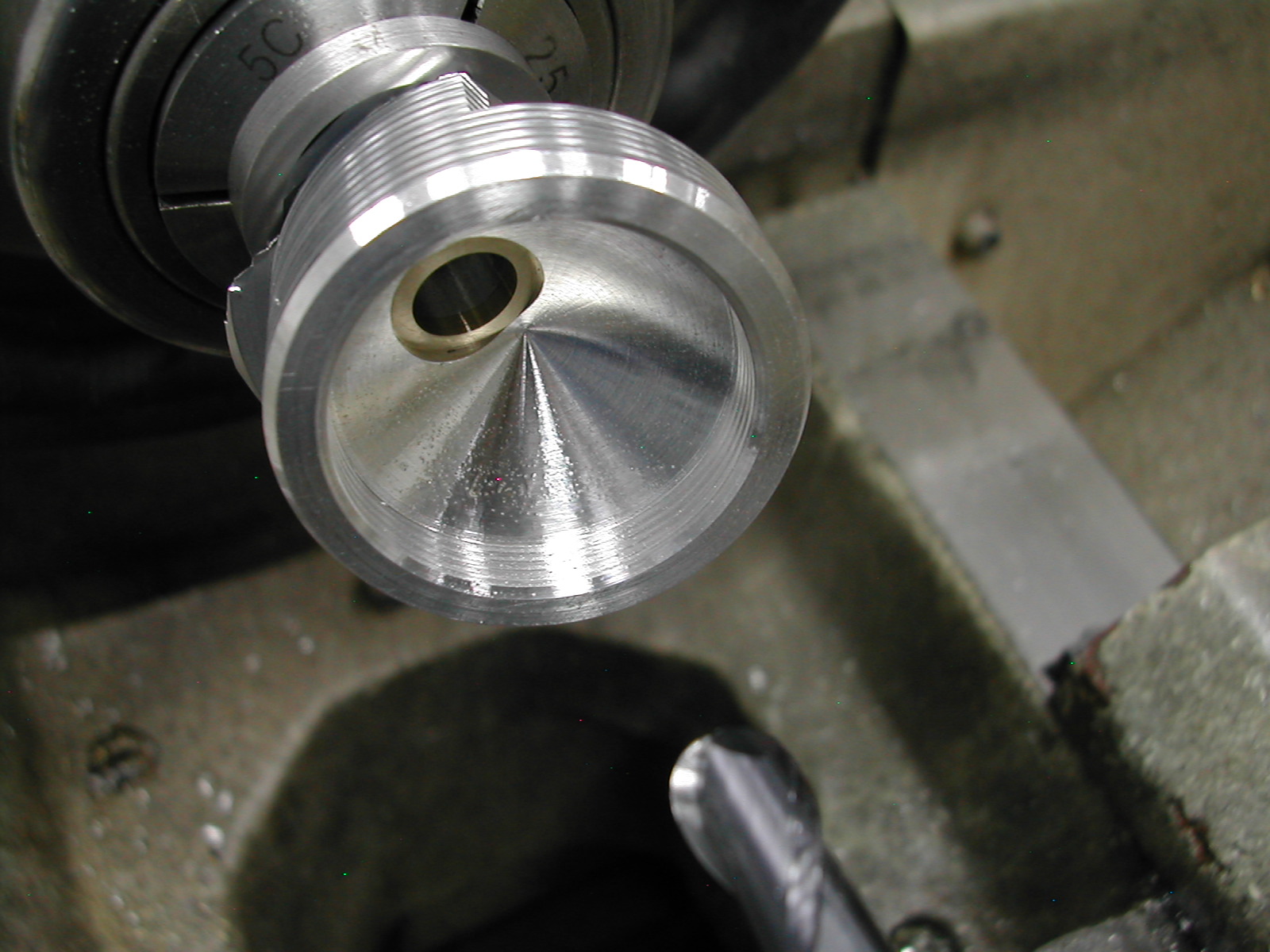
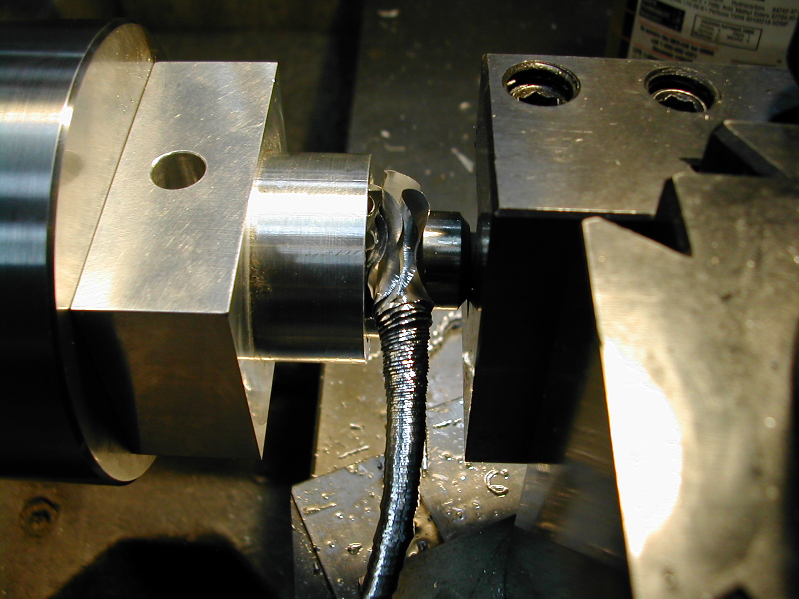 With the lathe running at 400rpm, you can see that the “D”-bit produced a very nice curl! Later on, you’ll see that it also generated a very nice cone with a great surface finish.
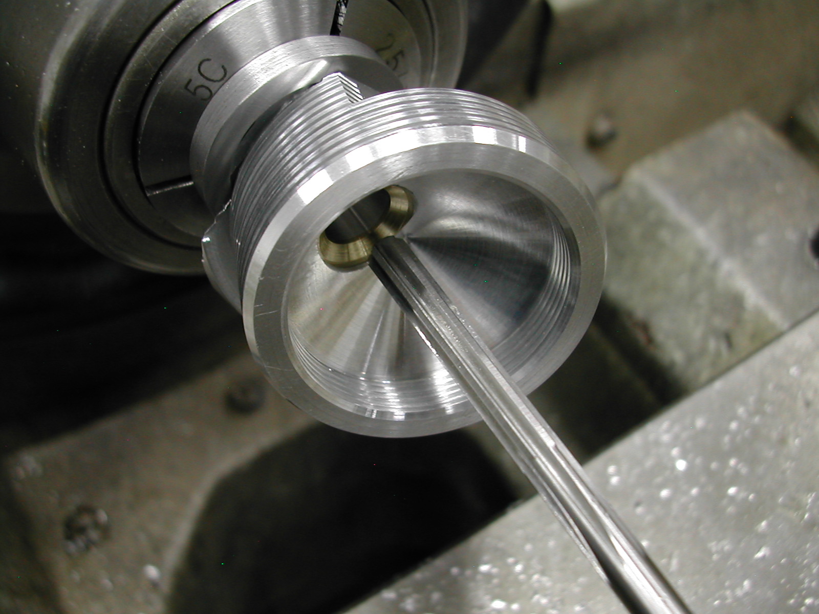
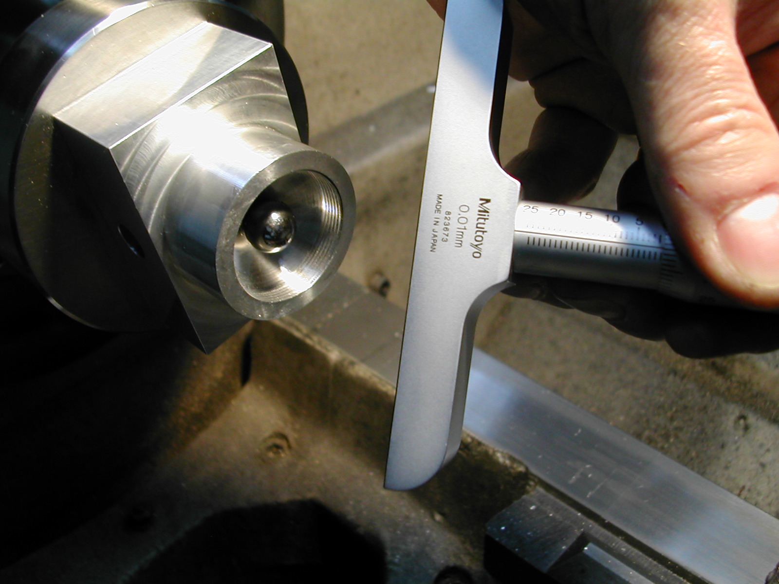 I’m checking the depth of the combustion chamber using a depth micrometer and a ball bearing. No, the lathe is not standing on it’s end – the ball bearing is held in the combustion chamber with some sticky grease while measuring.
 Next up was to add the 0.03″ thread relief and blend it into the conical section. This was one area where the drawings were not entirely clear. Here’s an 055 Head Crossection AutoCad 2010 sketch of what I went with. The 0.469″ circle was just the ball bearing that I happened to have handy.
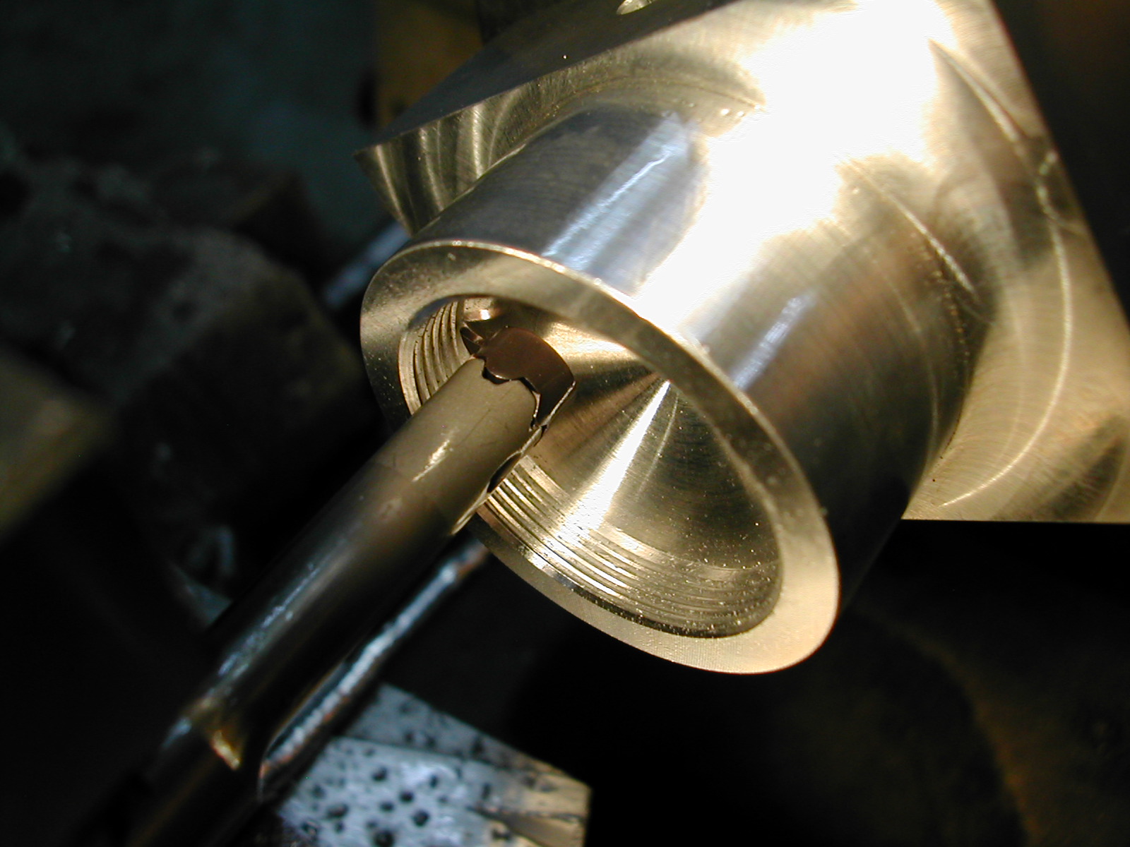
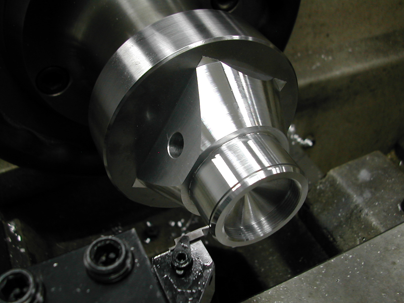
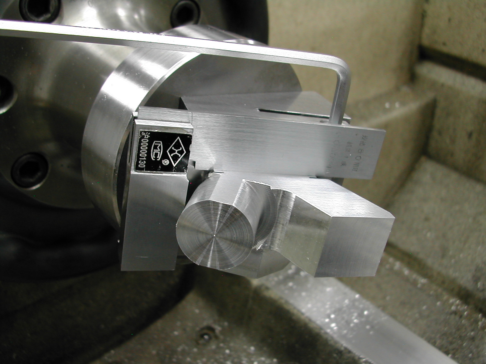
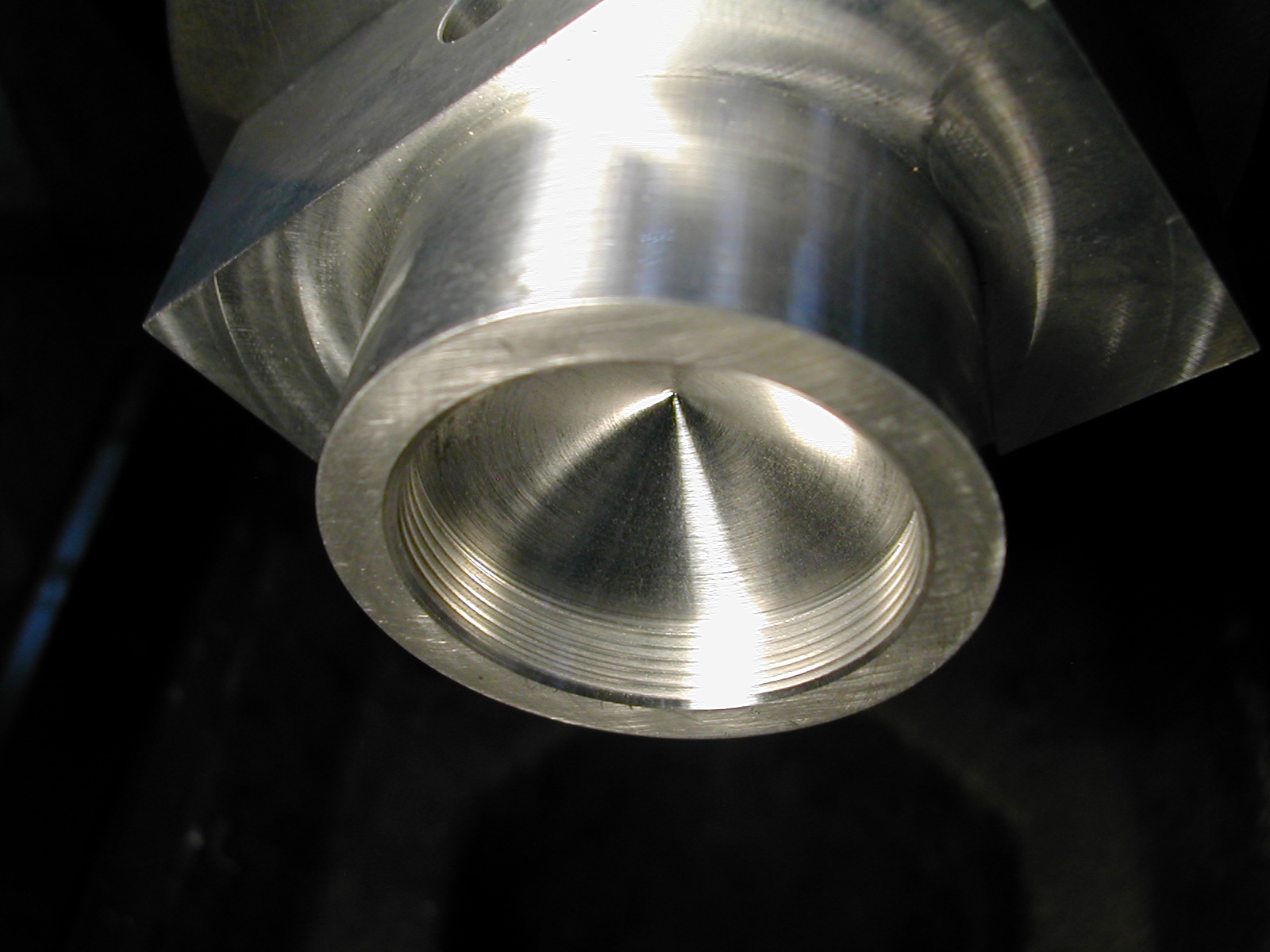 This is a shot of the finished combustion cavity.
 And here are the 11 heads with finished combustion cavities ready to begin on the outside details.
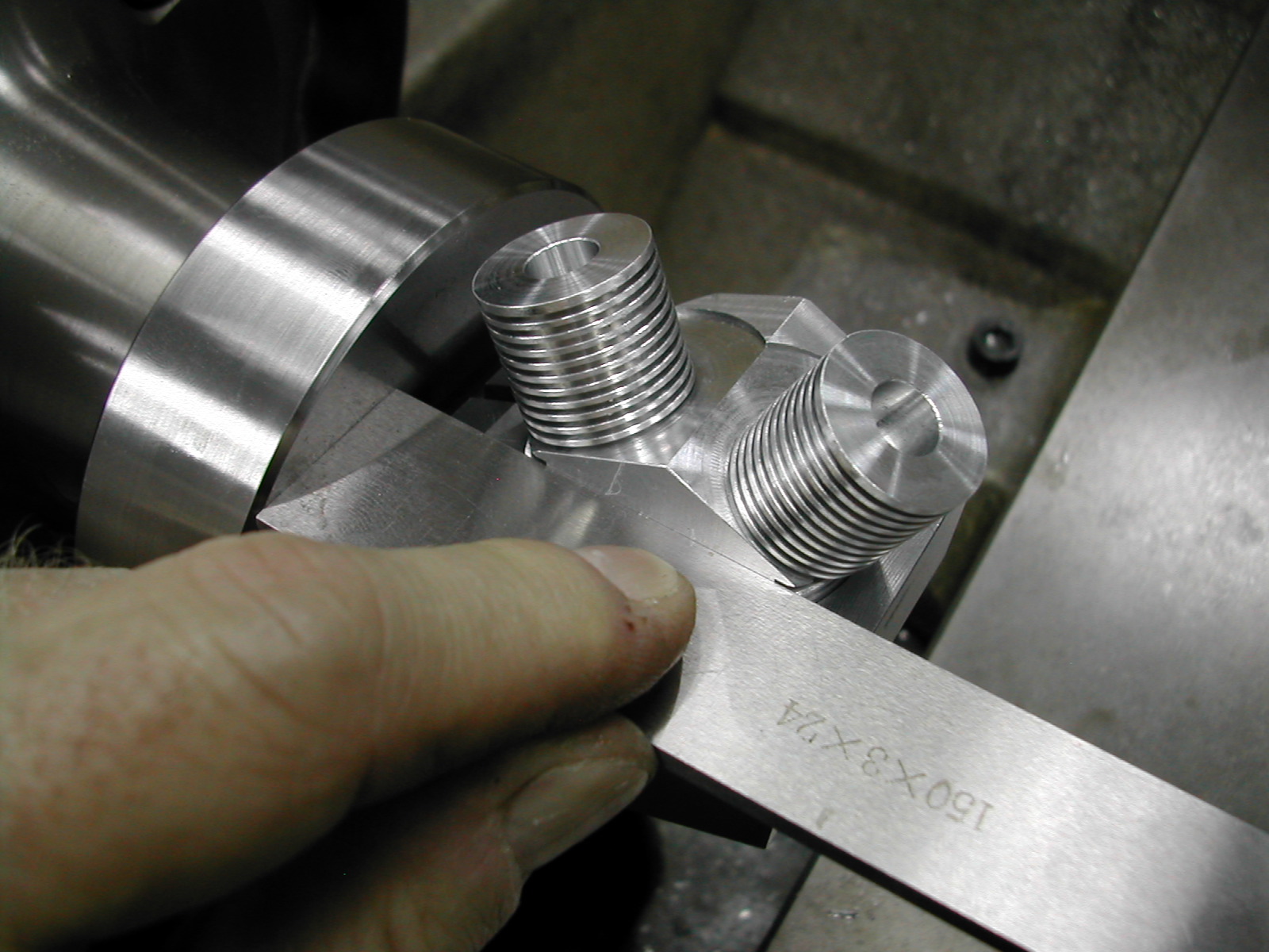
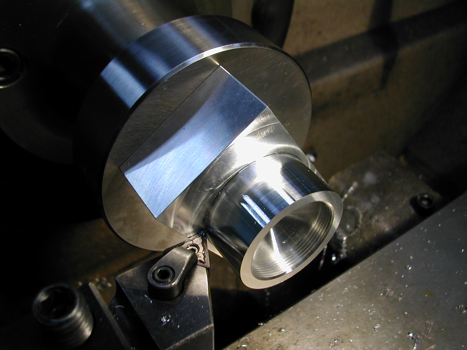 The next step was to turn the skirt OD to the 1.563″ diameter and verify this was a nice fit in tool CH2. The drawing shows the depth of this surface as 0.764″, but 10 fins and 11 slots @ 0.032″ are actually 0.762″.
 Since this was just a roughing cut, setting the crossslide to 25° using the graduations was close enough. At the corners, this angle will run past the face of the block so I machined as close as I could get without running into the faceplate. The small slivers left are easily knocked off with a file.
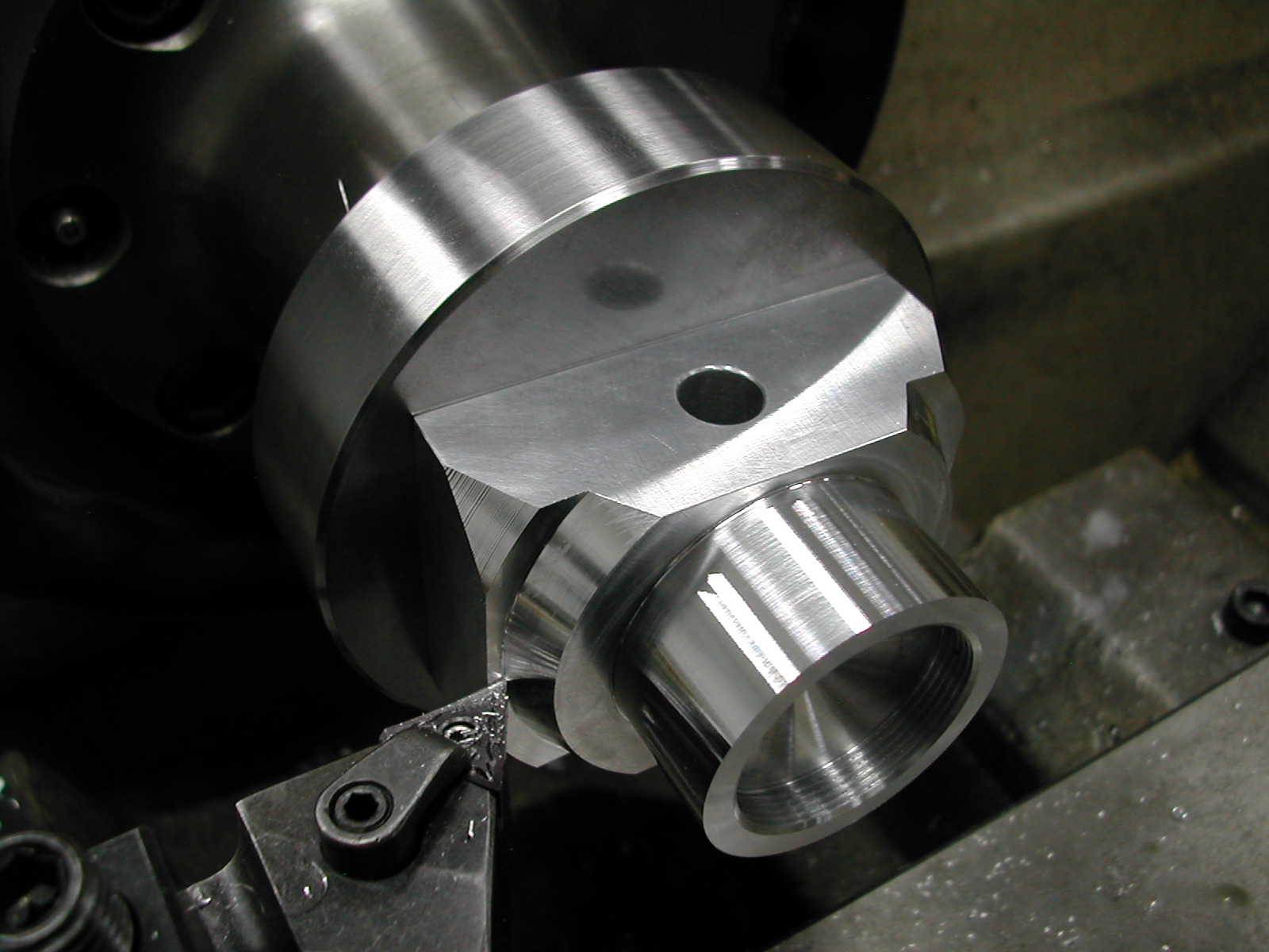
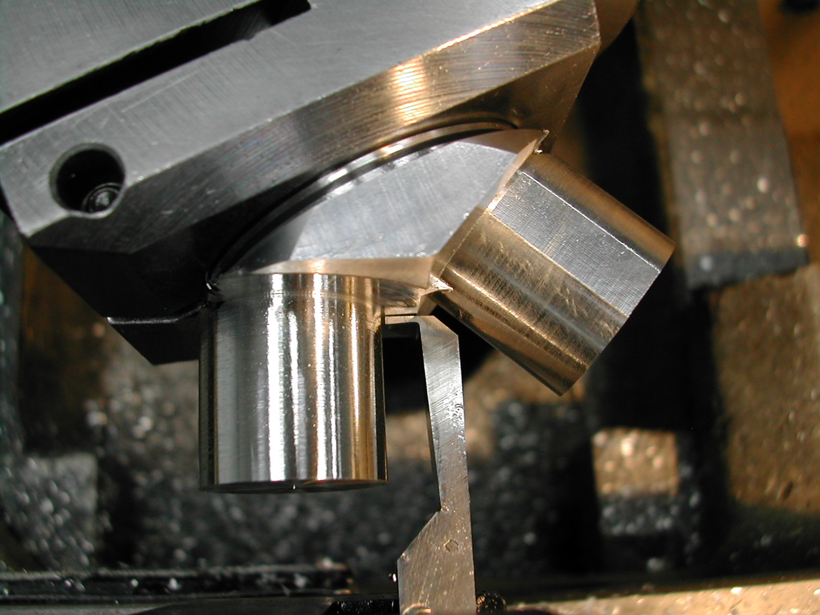
 Since the 30° chamfer was small, I was able to plunge it with a TNG insert without chatter so I didn’t need to keep switching the crossslide angle back and forth.
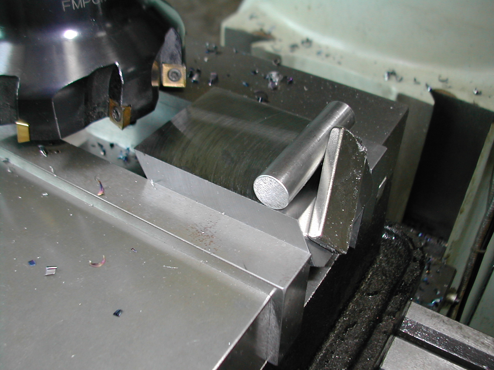
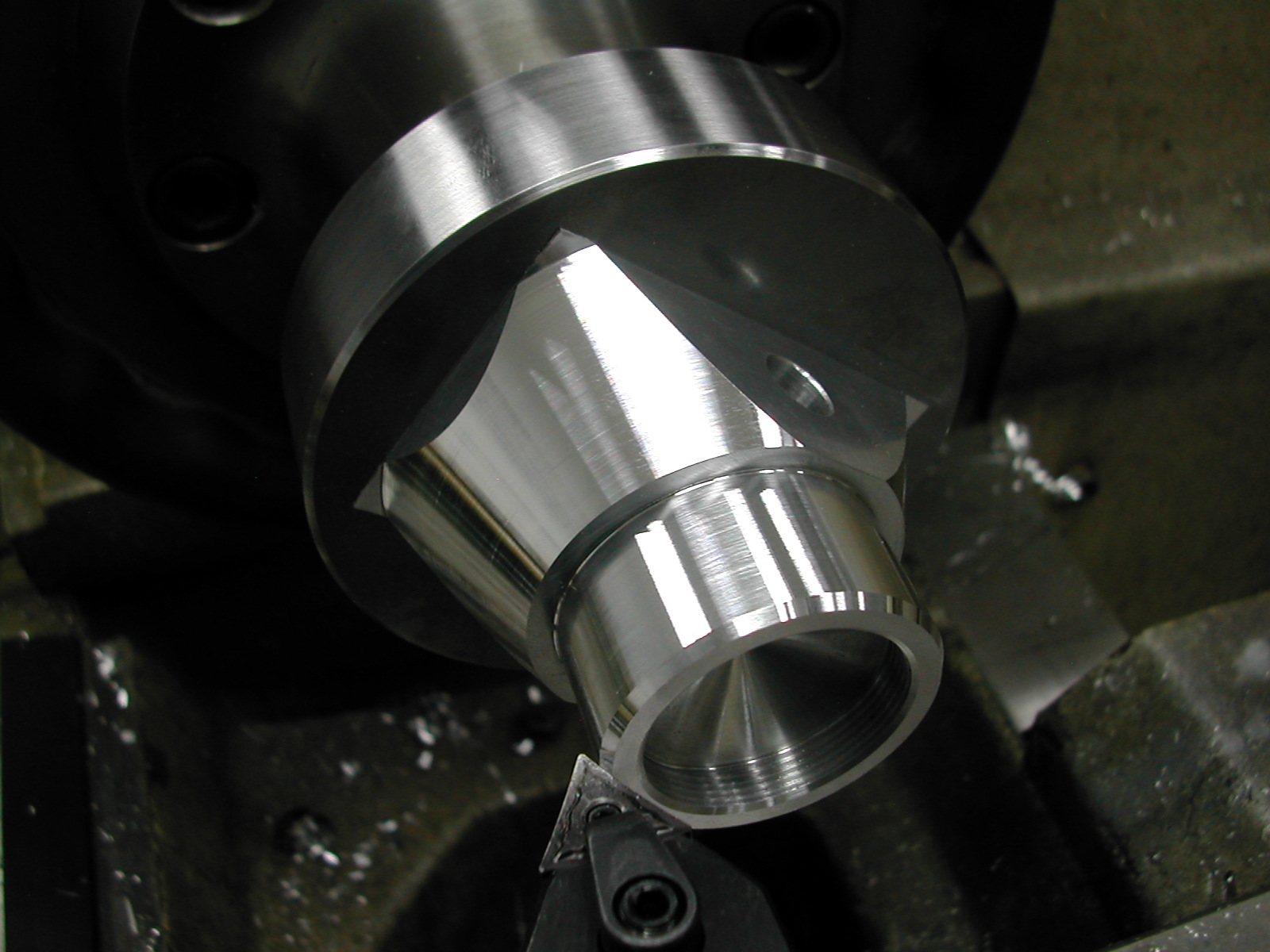
 Now we’re finally to the point where we get to see some visually striking changes occur with the addition of the cooling fins.
 Almost done with the fins on the first part. Ten more blocks to go and we’ll be heading to the mill for some more roughing out. The drawing states there are 10 fins and 10 slots, but there are in fact, 11 grooves to cut.
At this point these grooves are easy to deburr. I used a strip of 600 grit paper folded down the middle with the abrasive sides out. This slipped right into the grooves and the spring in the fold knocked the corners right down.
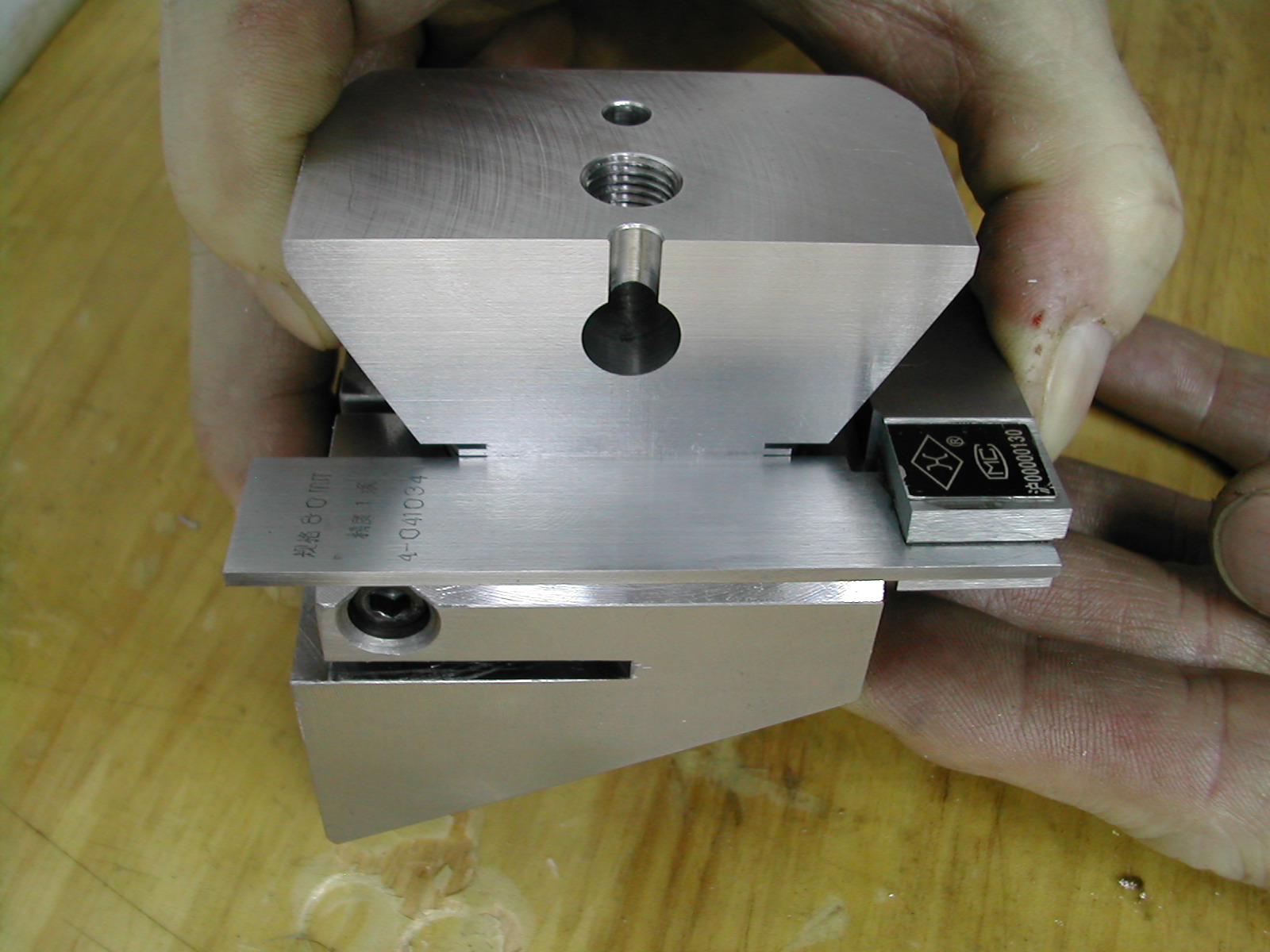
 Now we begin roughing out the valve towers. The first I’ll be making is the cut on the backside to create the intake/exhaust flange area. So, we need to set up tool CH2 with the top square to the mill. Side to side is not super critical so I’ll just use a machinist’s square instead of indicating the top. Front to back is the most critical here because this sets the plane of the exhaust flange and we want that perpendicular to the crankcase. Fortunately, the vise jaw handles this.
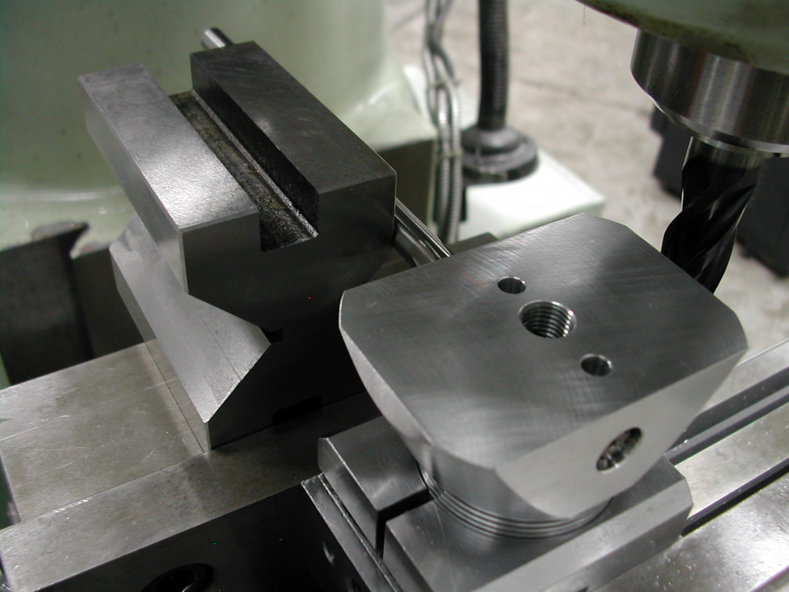 At this point, it’s not very easy to square the head with the mill, but luckily it’s not very critical at this point either. I’m using my 0.375″ reamer and a V-block to roughly align the hole between the valve towers to the mill, and a 0.250″ spacer is installed in tool CH2.
Once we make this first cut, it will be much easier to register the head in the fixture, and it’s only after we make this first cut that it becomes important to accurately align the head in subsequent cuts.
 This is the start of the intake/exhaust flange area. I’m 0.005″ above finished height in Z and I’m whittling towards the 0.406″ dimension 0.050″ at a time.
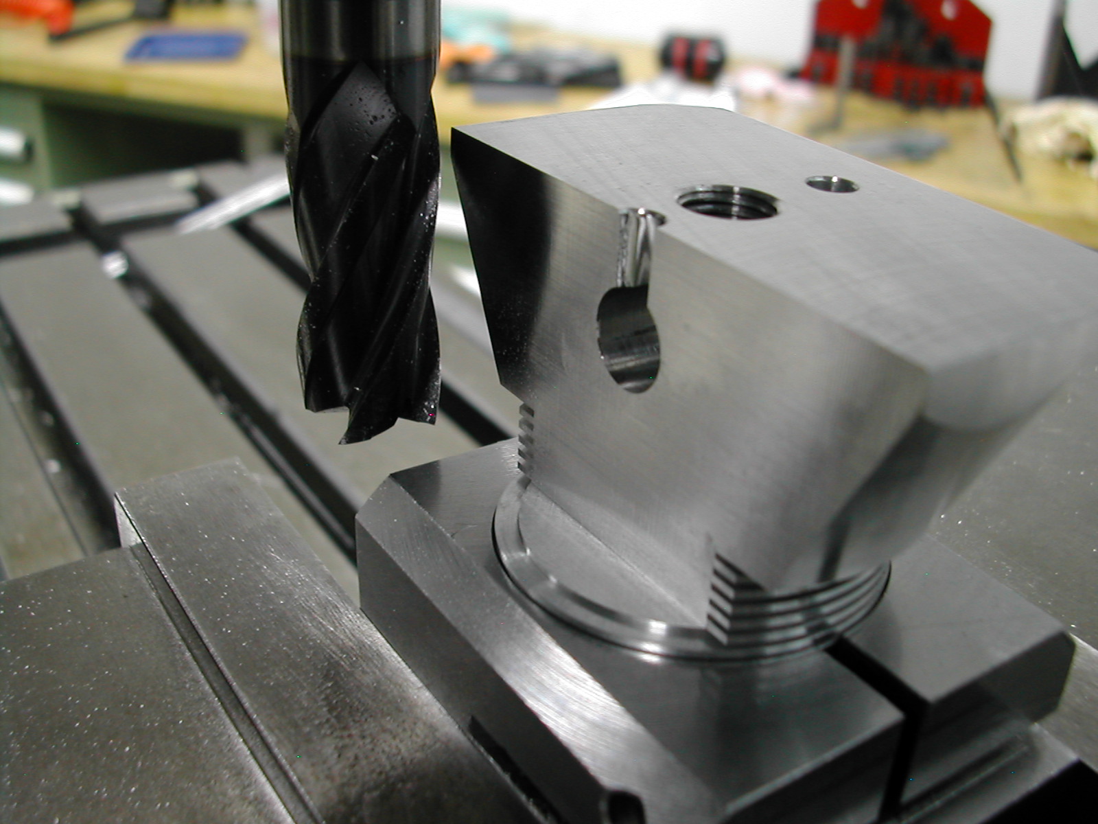 It’s kind of hard to verify when you’ve reached 0.406″, but if you accurately squared your stock and held the 1.750″ dimension, you can measure from the front surface of the blank and mill ’till you reach 1.281″. Measure from the center of the head in case the block is slightly skewed in respect to the mill axis.
This is the only cut we’re making in the mill that’s important to try to maintain the specified dimension, and you want to shoot for a good surface finish as this is a finished surface that mates with the exhaust gasket. When you finish this cut, repeat the procedure on the remaining head blanks.
 Now we’re ready to begin wasting on the front side. All surfaces generated with these cuts get further material removal later, so accuracy is not overly critical at this point. Here, I’m aligning the intake/exhaust flange cut made previously with tool CH2 in preparation to making the 25° cut on the front side.
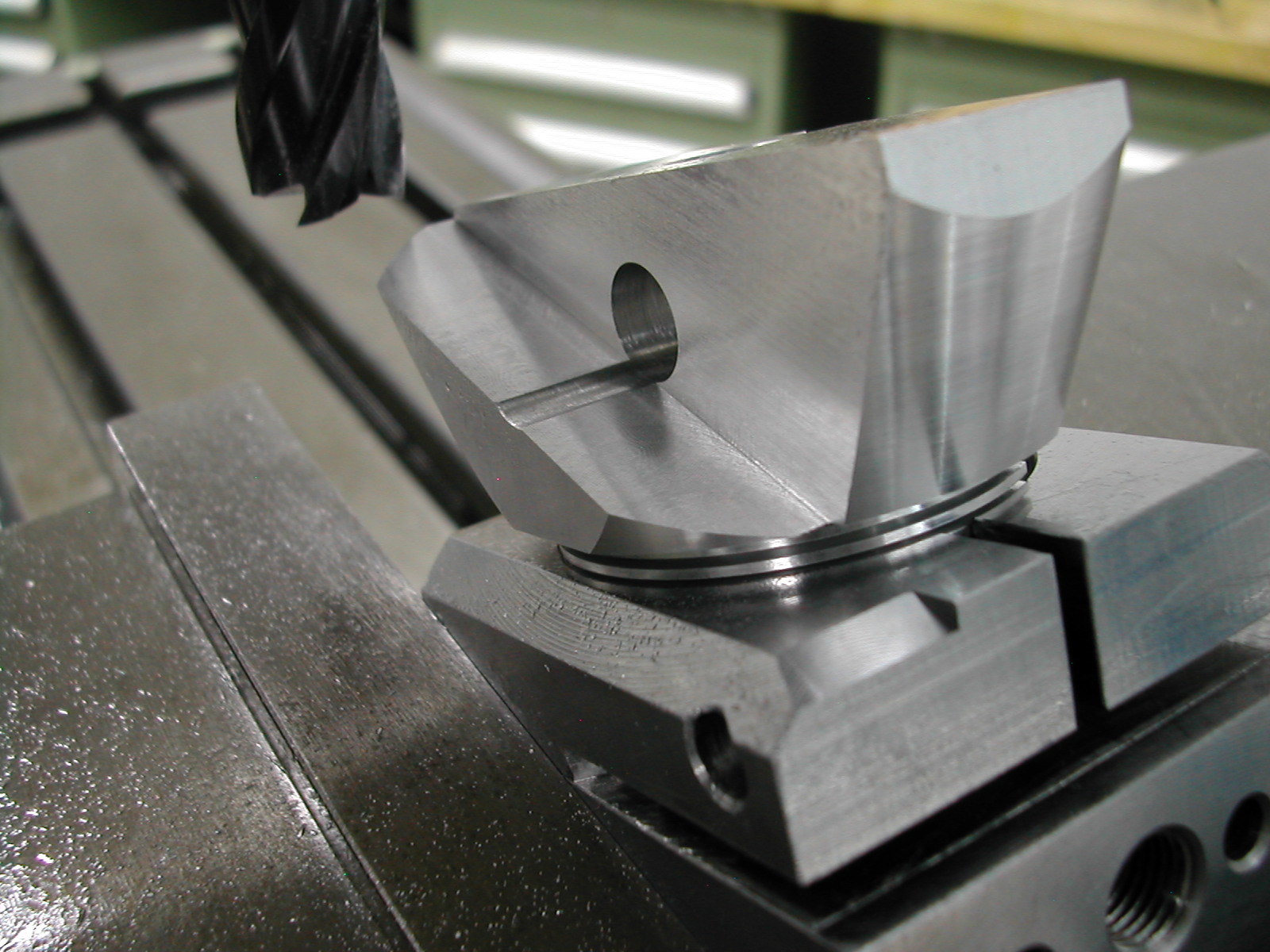 With tool CH2’s 25° angle resting on parallels and no shims installed, we make the first cut following the same whittling procedure used on the back surface. You can take tool CH2, with the part still firmly clamped in, out of the mill vise to easily check the 1.589″ depth.
The 0.406″ dimension is now easily checked by measuring across to our previous cut and shooting for 0.812″. Repeat this cut on all the head blanks before proceeding.
 Rotating the part 180° in tool CH2 and again aligning it with the machinist’s square before tightening, sets us up to cut the remaining 25° wasting cut.
You’ll use the same depth and Y axis numbers you used on the last cut. Don’t worry if the finish plane of this surface does not match up perfectly with the previous cut.
Now do the rest of the blocks.
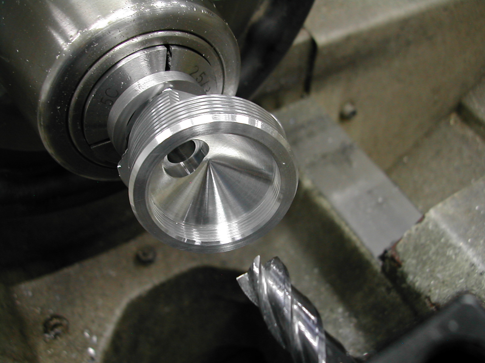
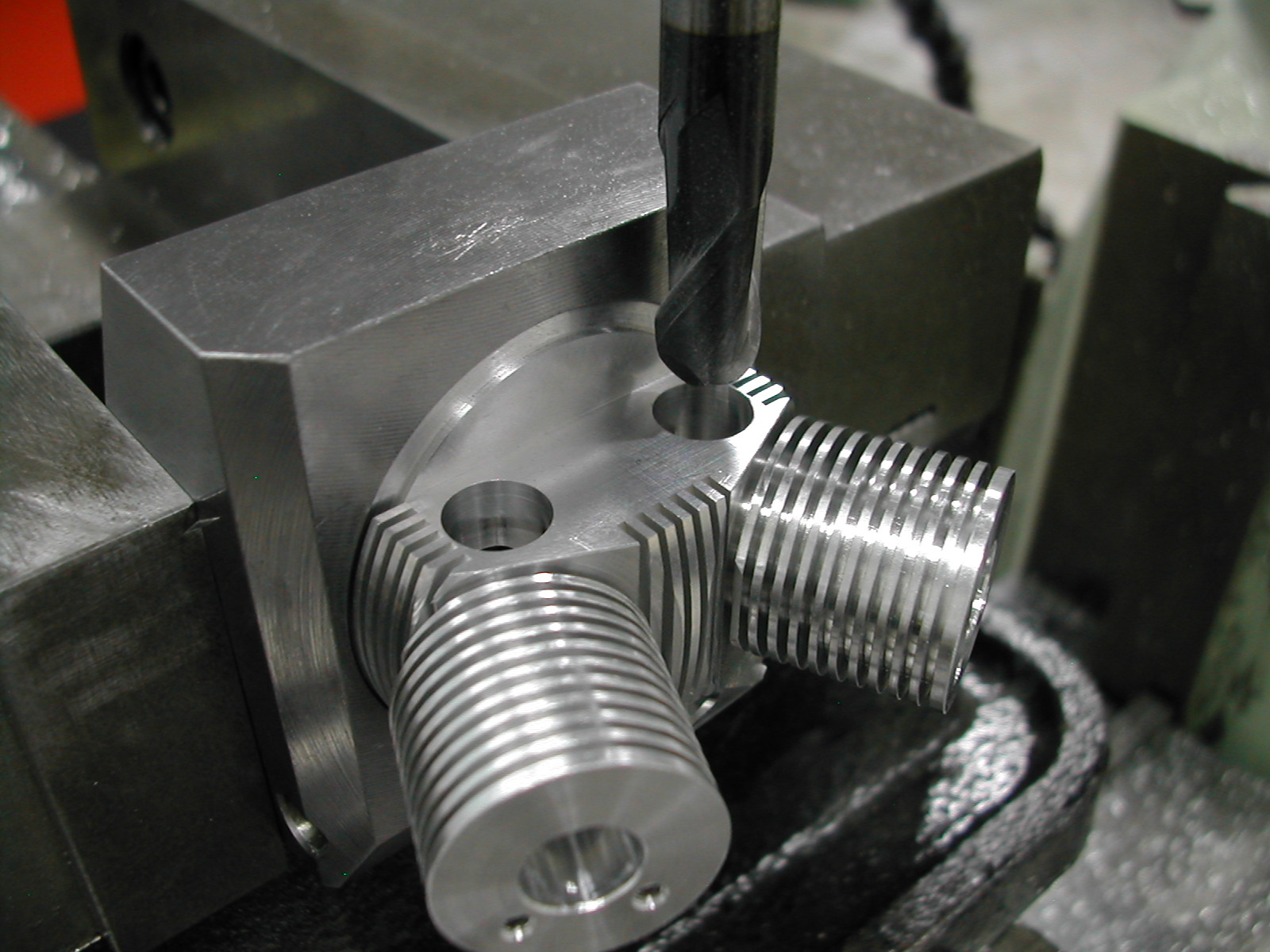
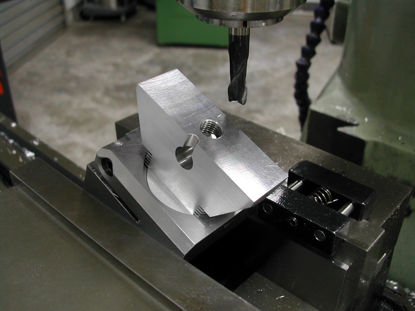 With just about any endmill smaller than 0.375″ go ahead and clean out the material on the first side between the valve towers.
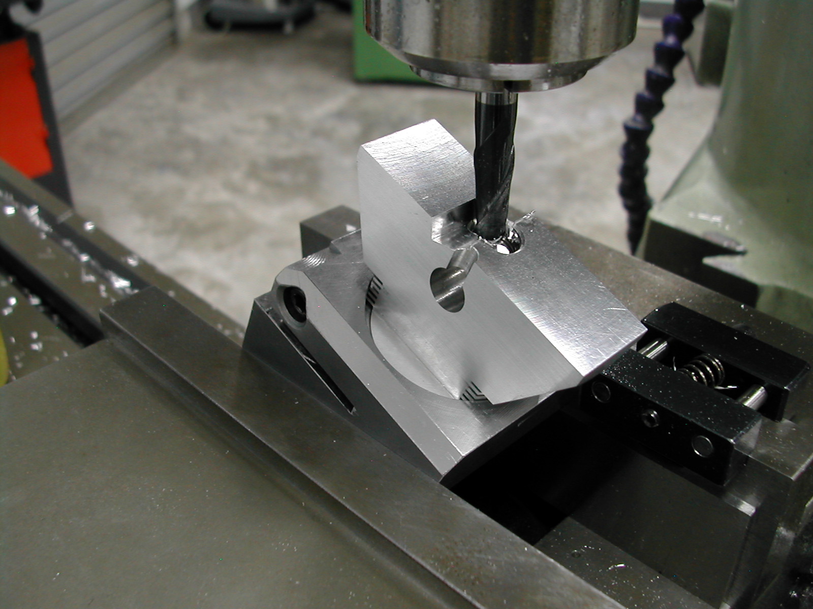 Machine down to approximately the center of the previously drilled hole and tangent to the side.
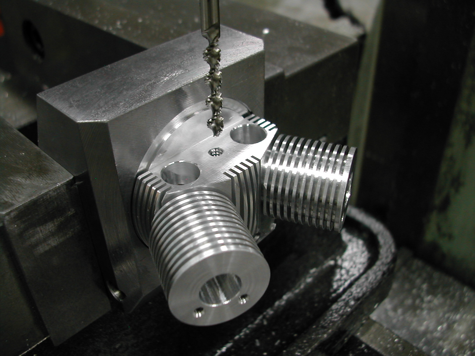
Here, you can rotate the part and clean up the other side before moving on, or you can clean out this one side on all the blanks before moving on and doing the other side.
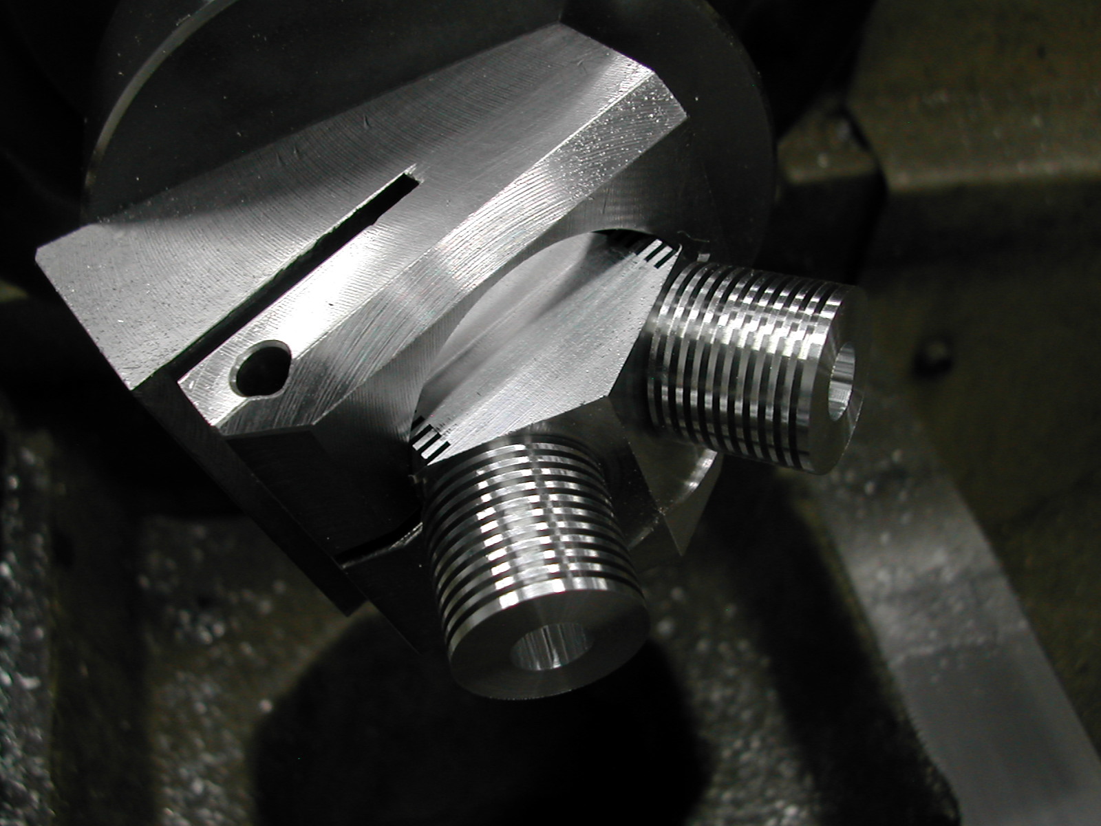
 With the removal of the material between the valve towers, we’re done at the mill for now. The next step will be at the lathe to begin turning this “V” into real, finned valve towers.
 Mount CH2 on the faceplate and without any shims, align and clamp one of the cylinder heads in the tool with either of the valve towers in-line with the spindle centerline.
 Begin by facing the top of the valve tower to a little longer than the 2.281″ dimension, checking with a depth mic as you go along. We’re just roughing in this first tower so we want to leave a little to clean up later.
 Now, I’m roughing in the O.D. to the 0.85″ finish diameter starting from an initial outside diameter measured to the outside edge of my tool of about 1.23″. I’m also stopping short of the 0.719″ length to leave some material when I come back to finish machine this tower.
The process I use here is to plunge with my tool starting at the large diameter to just short of the depth. I then back out, reduce the diameter by just shy of twice the width of my tool and plunge in again. This is repeated until the diameter of the valve tower reaches the 0.85″ dimension.
 Here is the first valve tower roughed out. I’ve got my cutter positioned at the 1.23″ outside range of my roughing cut in this photo.
 With the head flipped so the other valve tower is inline with the spindle, I’m ready to begin roughing and finishing the second tower.
 For the second tower which I will be finish-machining in this setup, I’ve already faced the top to the 2.281″ dimension. Now, I’m starting to round out the tower with a much larger starting radius. In this case, with the tool at the finished depth of 0.719″, I begin interfering with the other roughed-out tower at about 1.46″ in diameter. That’s what I’ll use to start plunging and whittling this second tower down.
 The process for cutting this tower is the same as previous. On each of my plunge cuts in, I’m stopping at 0.715″ deep. On the last pass when I plunge the O.D. of the valve tower to the 0.781″ finish dimension, I feed into the final depth of 0.719″ and then feed away from the valve tower to the 1.46″ large diameter to clean up this face. This final 0.004″ pass will remove the slight chatter you see in this photo left by the roughing cuts.
You’ll want to make sure you do a pretty good job of holding the 0.781″ finish O.D. on the towers since you’ll need to grip on this diameter in later operations.
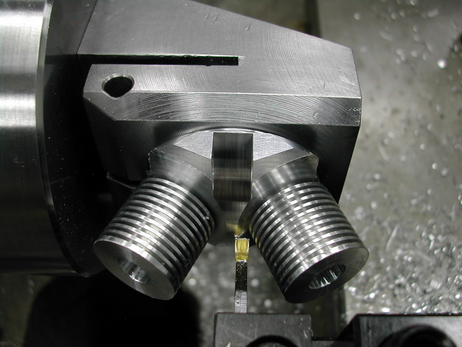
 With this valve tower now at the finish O.D. and length, I can begin putting in the fins. Starting with the fin just touching the previously finished 0.719″ surface, I put in 5 grooves at 0.240″ off of the diameter followed by 6 grooves 0.156″ off of the diameter.
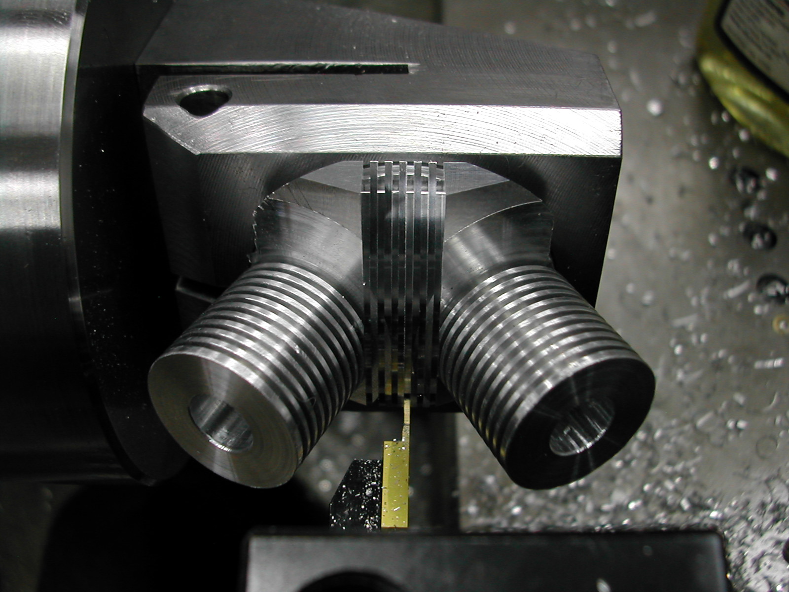
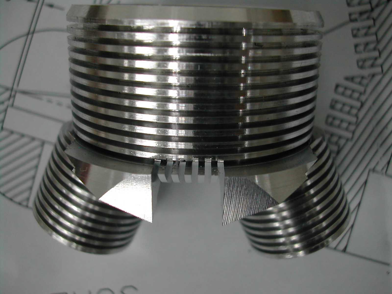
 Here’s the last of the valve tower grooves going in. It’s going to be tough to deburr these fins since we can’t get a strip of sandpaper in here with the spindle moving. Looks like it will be a couple of hours getting acquainted with the needle files.
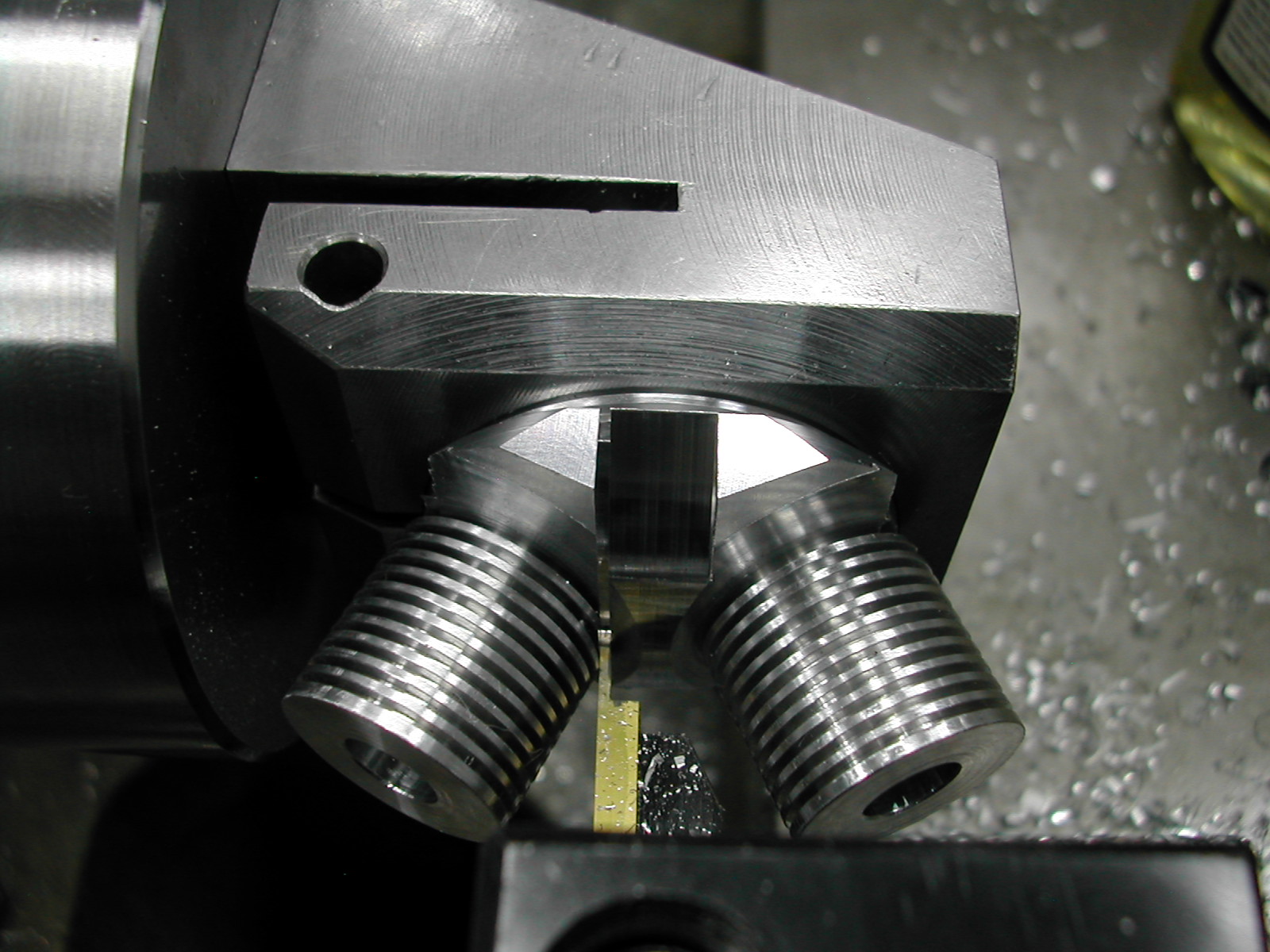
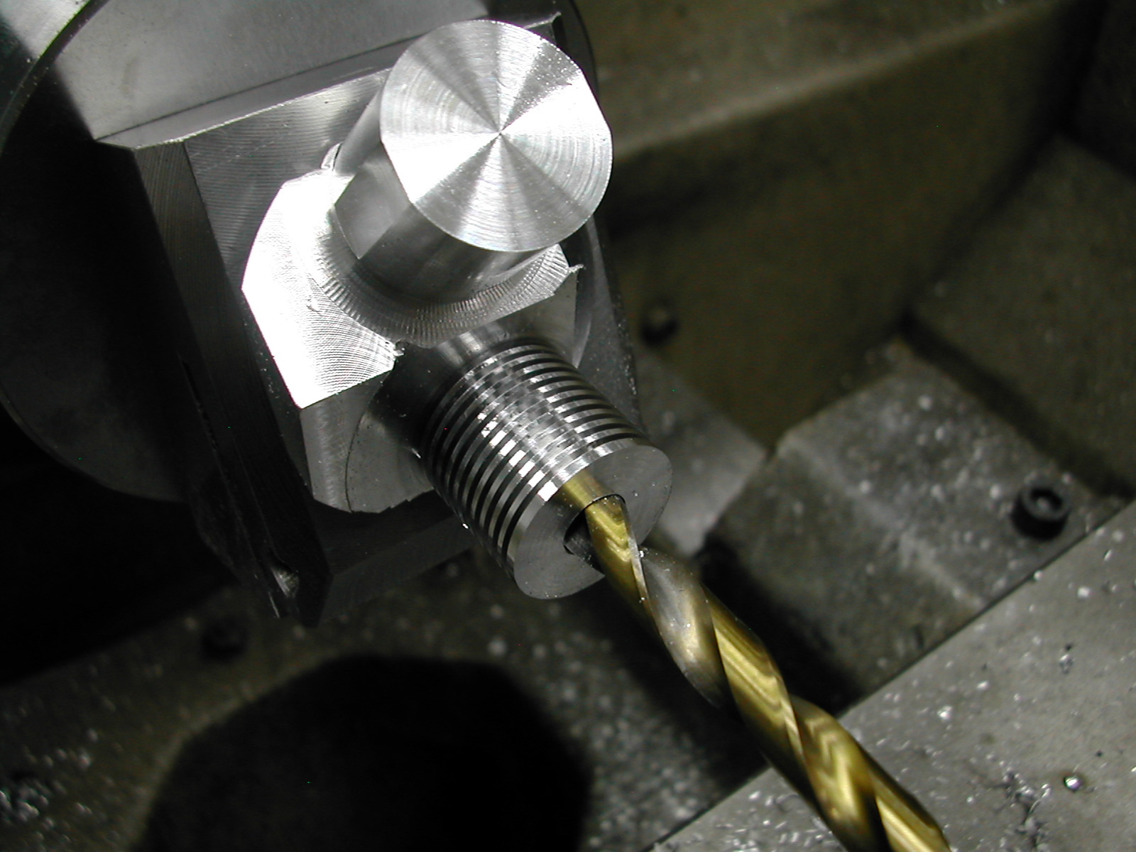 Center drill and then drill with a 5/16″ bit to rough out the valve spring hole.
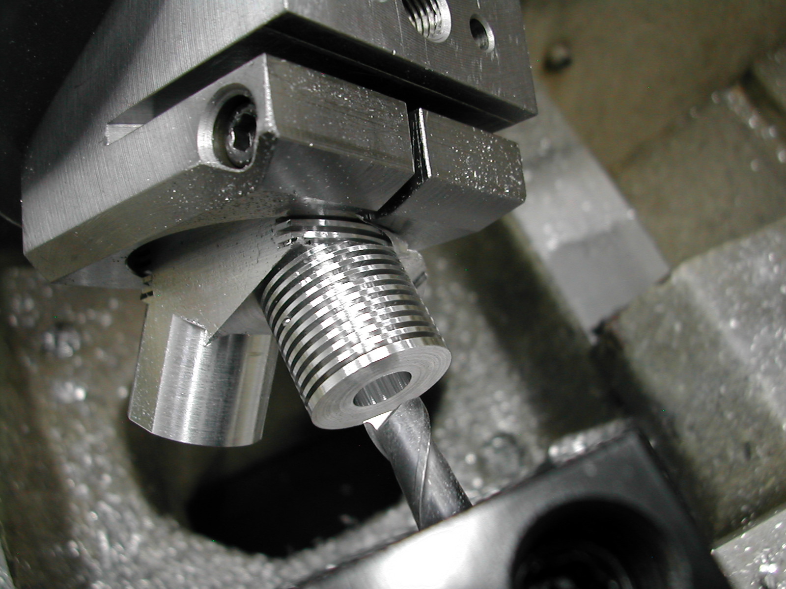 Now, I’m finish boring the valve spring hole to the final depth of 0.343″. Using a 5/16″ endmill for this gets me a flat-bottom hole at the same time.
Now that the second valve tower is finished, it’s time to go back to the first one that was just roughed-out and finish it. The reason why I left this roughed-out tower a little longer than the 2.281″ finish length is because when we rotate this first tower back into place we might not get it in the exact same location.
 By leaving a little extra on top and taking the finish cut after the tower has been rotated the final time, we insure that the top of this tower is exactly perpendicular to the finish O.D.
Begin by facing this tower to it’s final length, then start turning this valve tower where we used the 1.46″ diameter to start the finish turning of the previous tower.
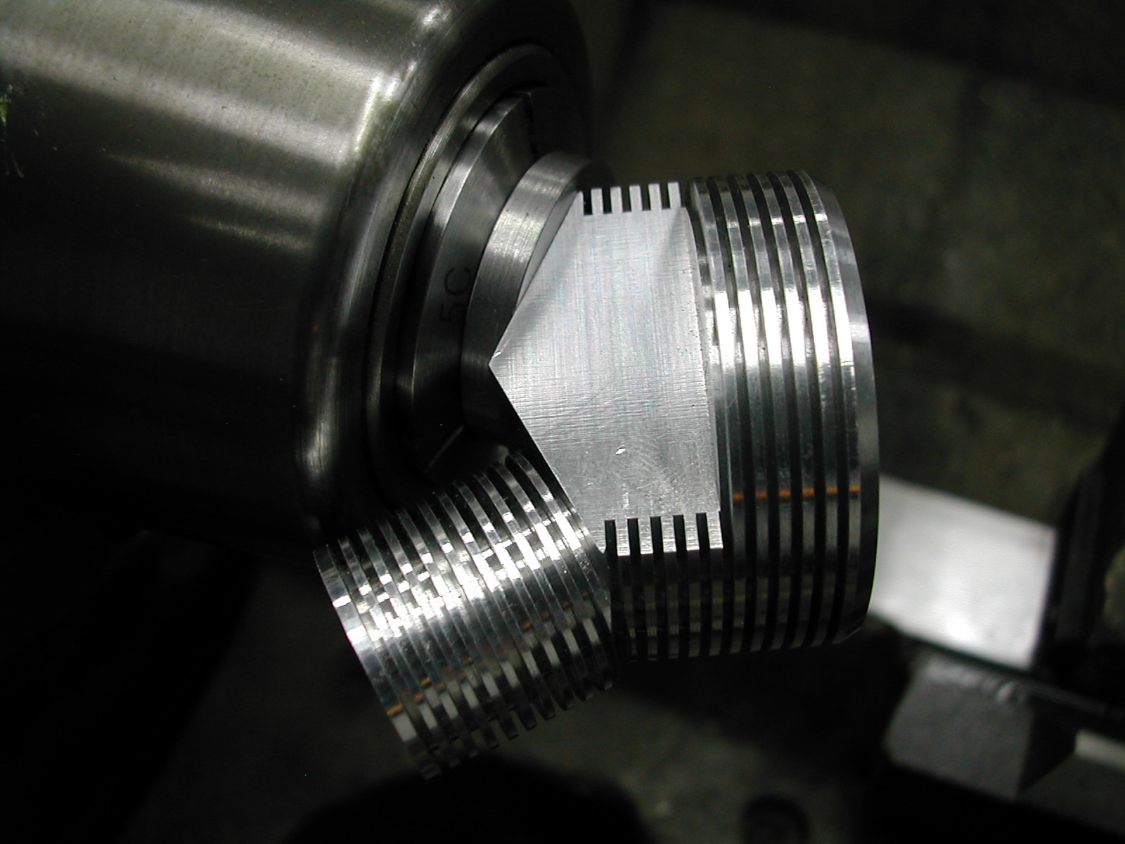
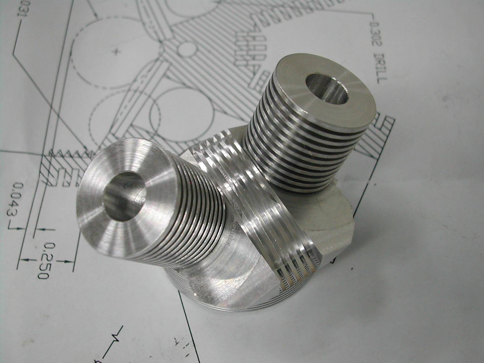
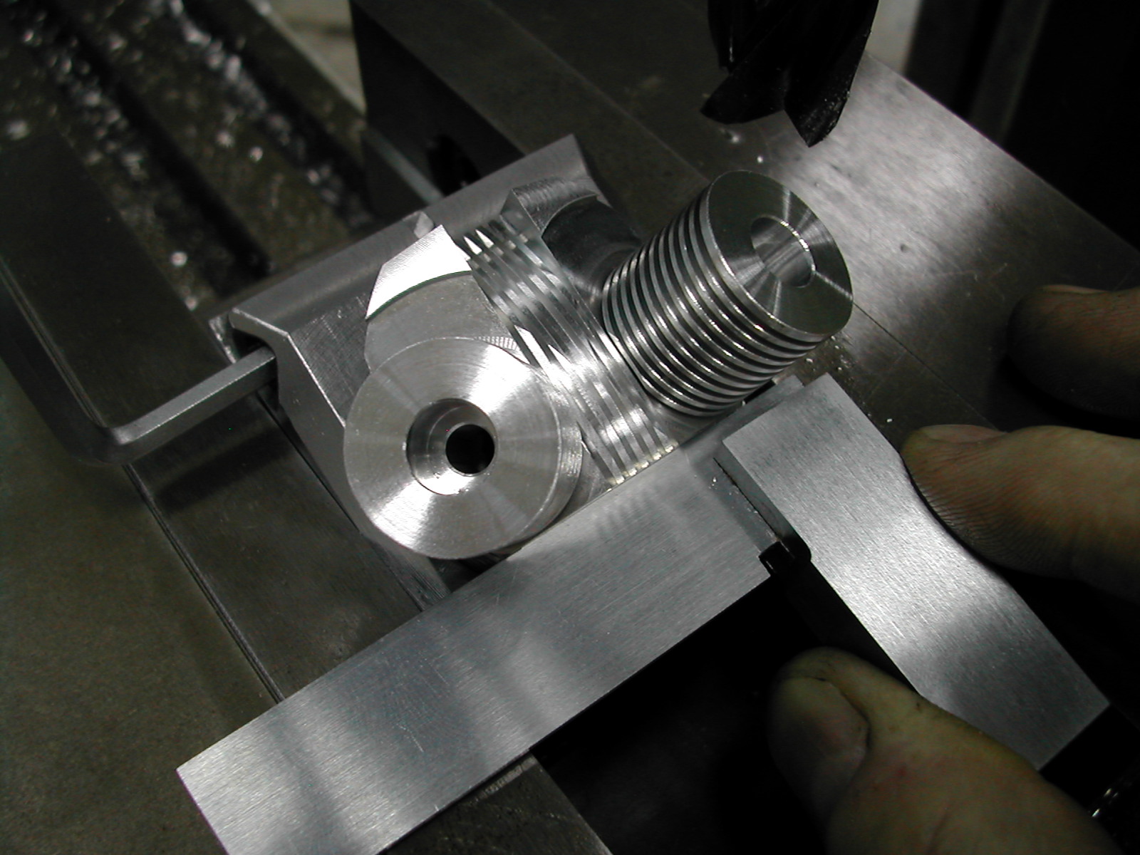
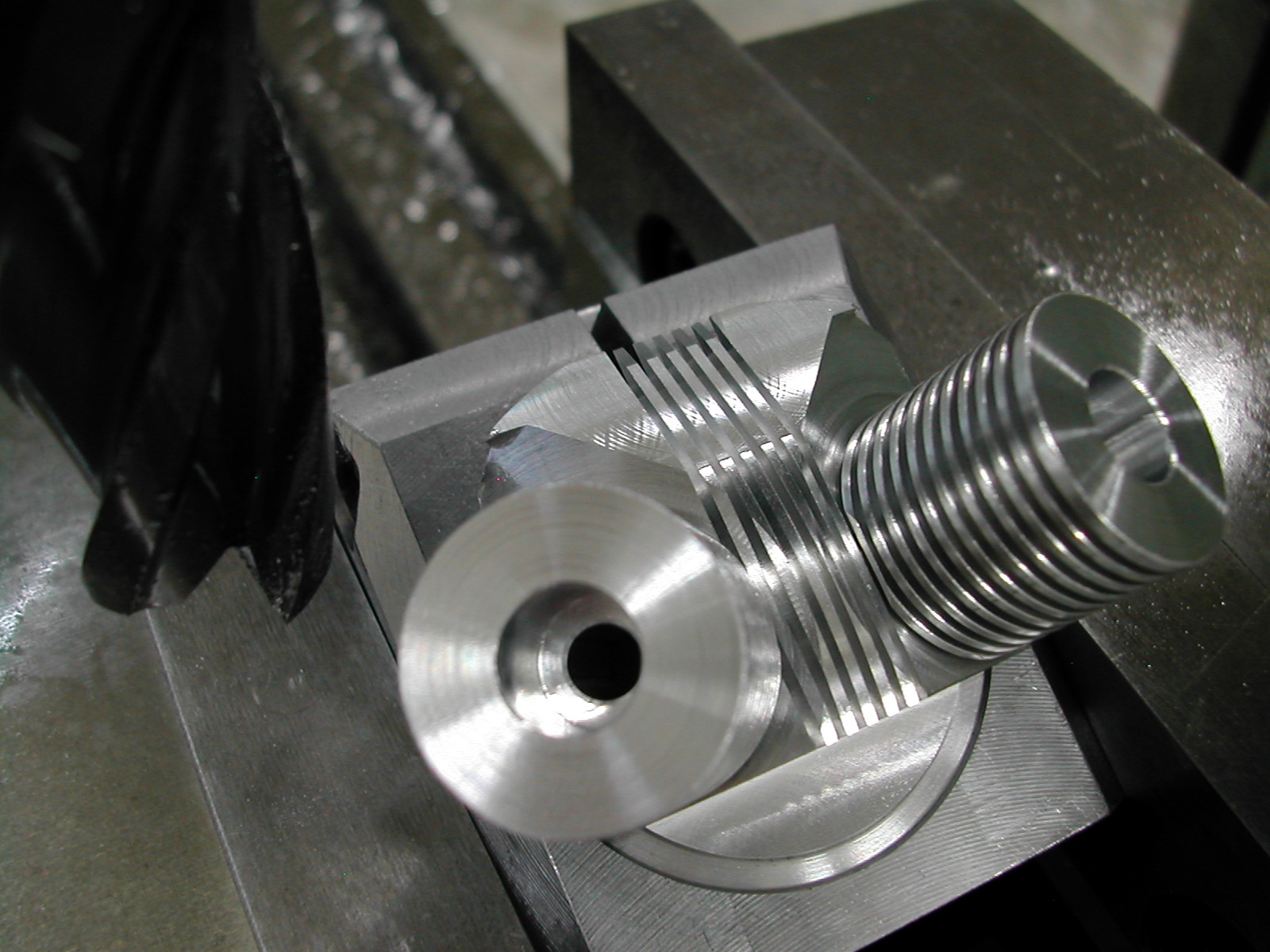
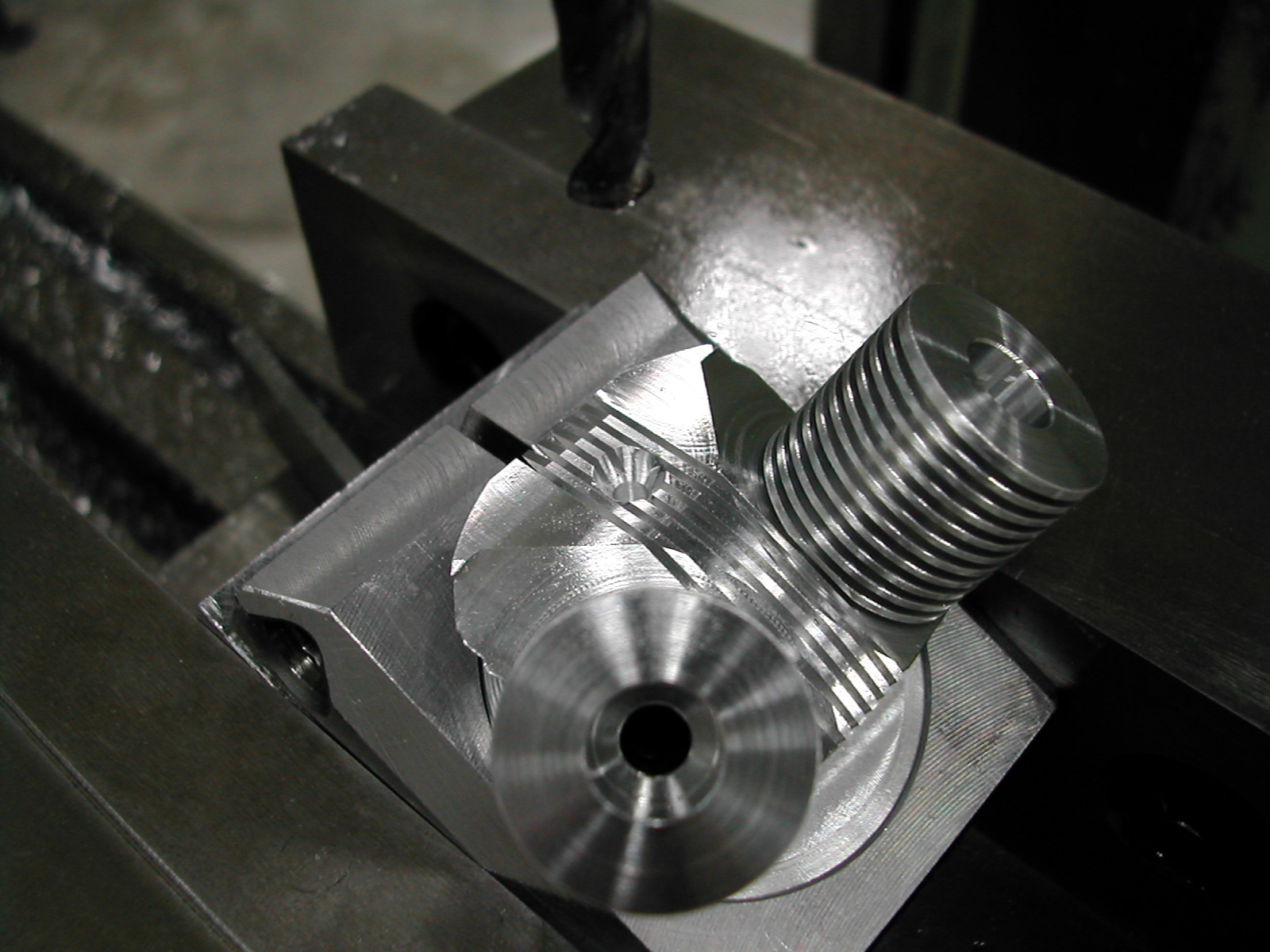
 The first head with both valve towers finished! I have another ten more to get to this point before I can move on, then some quality time with the needle files to deburr the valve tower fins so the parts will fit easily into the 5C collet for the next step.
At this point, I begin to change the order and, in a few sections the substance, of the original process sheet provided with the plans. Here is my revised process plan (055 Head Operation Sheet) I will be following from here on.
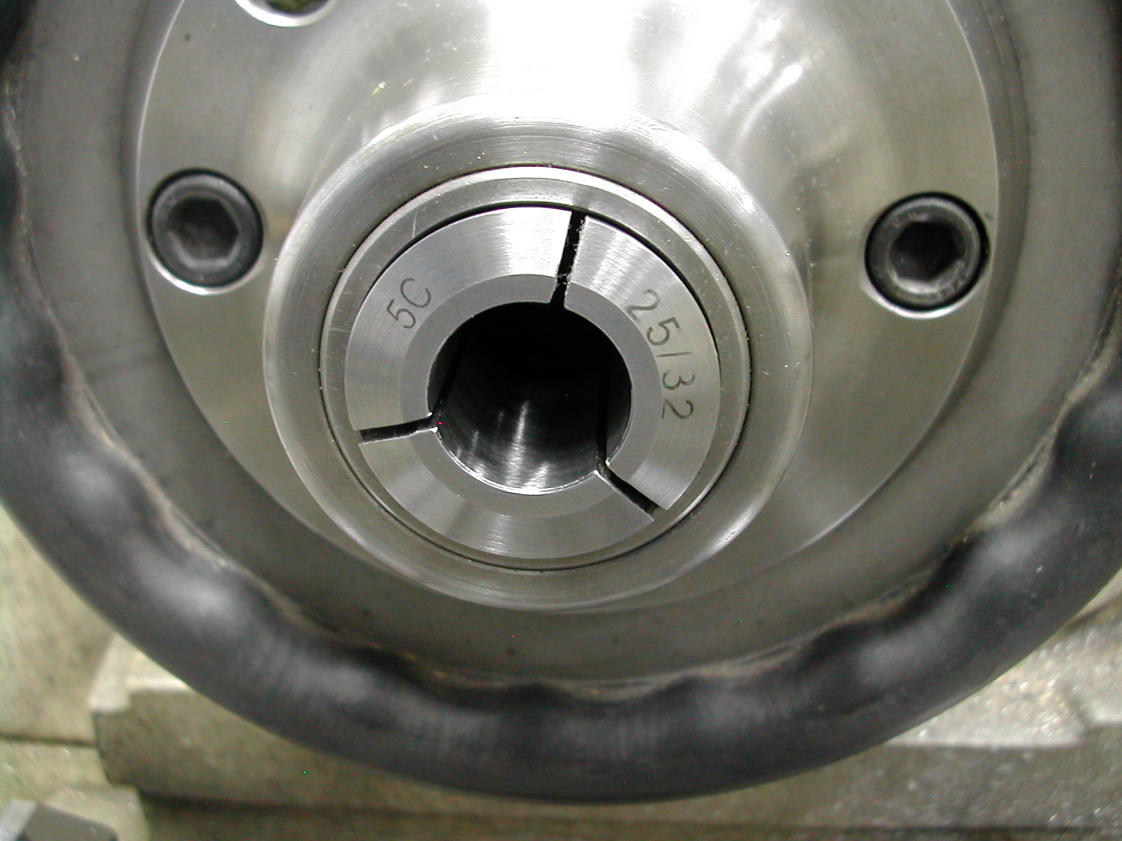 To work on the internal portion of the valve towers, I modified a 25/32″ 5C collet to have a flat on the end. A light cut with a carbide tool and a little lapping produced a nice flat with which we will register the head.
 Because of the large outside diameter of my 5C collet chuck, I needed to make a small spacer to move the head away from the collet so the second valve tower would clear the chuck.
I changes the order from the original process sheet and machined the internal portion of the valve towers before the top cooling fins so that I would have a nice flat surface on the top of the head to register against the 5C collet.
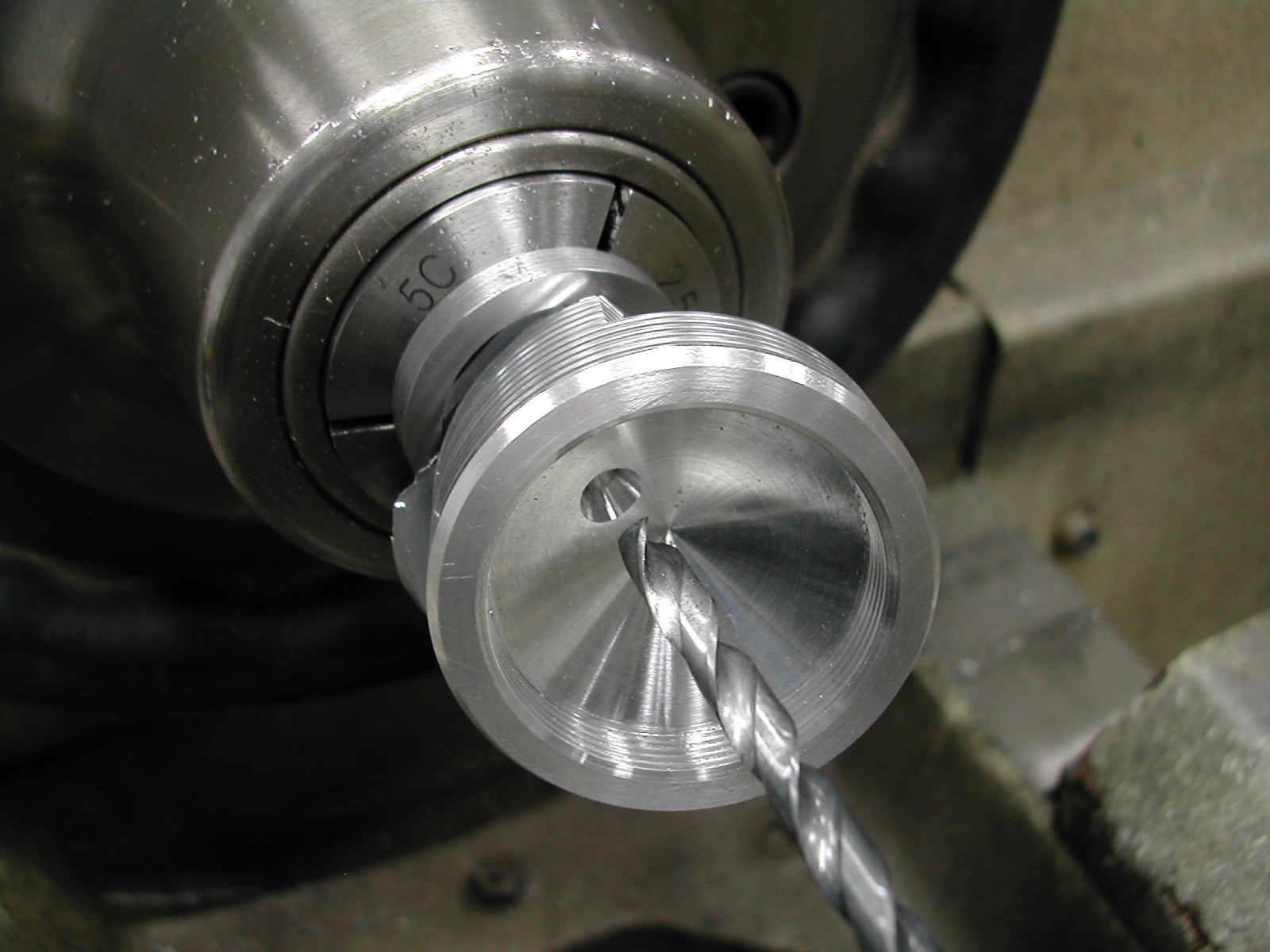 With the head chucked up, I proceeded to centerdrill and then drill 0.177″ (#16) through.
 This was followed with a 0.302″ drill 0.393″ deep to provide clearance for our valve seat swaging tool.
 Then the valve seat cavity was roughed out with an endmill to the required 0.078″ depth, but a little under size on the diameter to allow the next tool to clean it up to the final O.D.
The depth on this cavity is a little tricky to check because of the conical combustion chamber so I finally used my CAD drawing to measure the distance from the bottom of the cavity to the top of the valve tower. I then removed my head from the 5C collet to check this 1.141″ dimension.
 I then finish bored the cavity O.D. to 0.470″ and added the 0.010″ per side undercut.
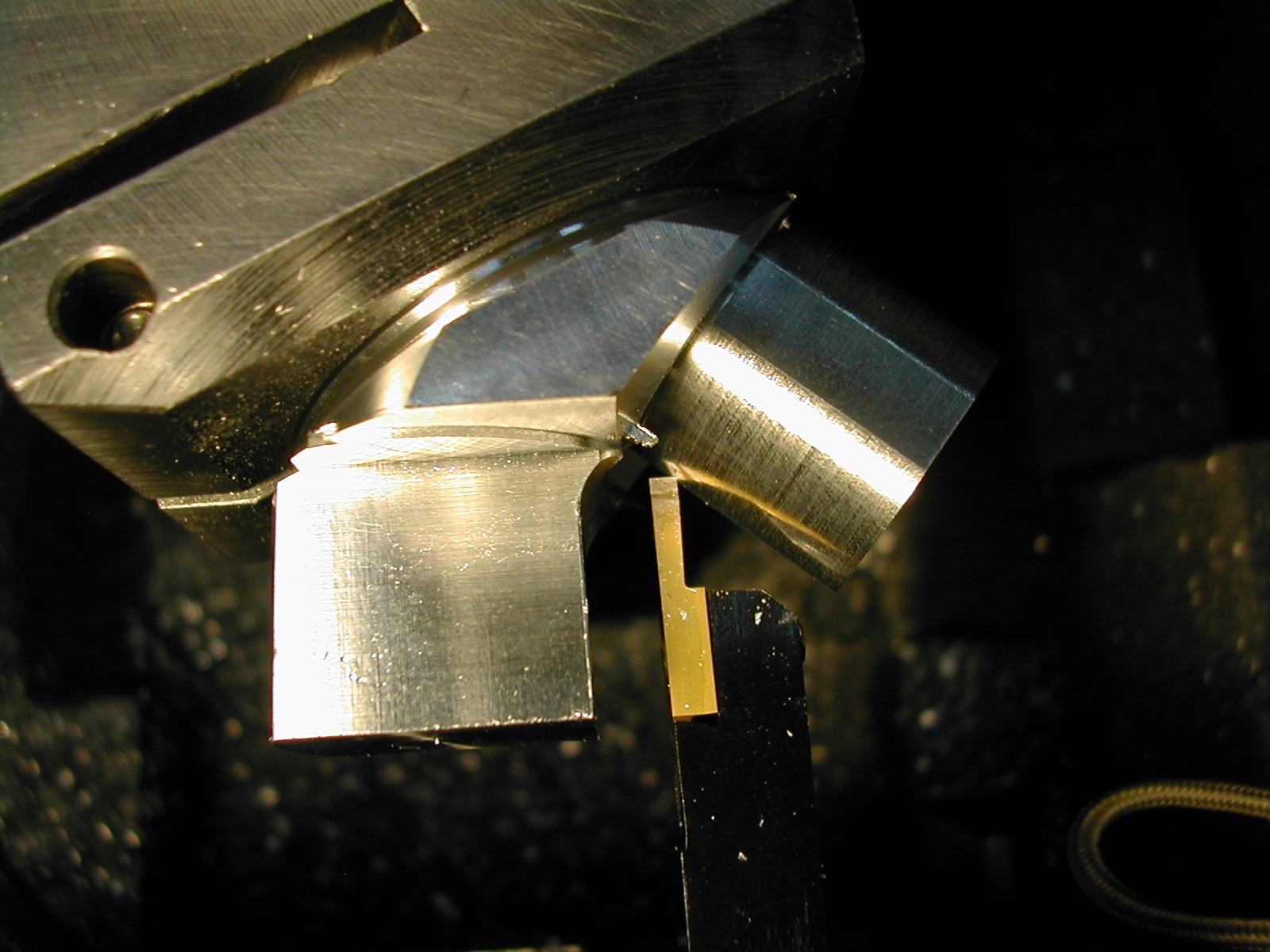
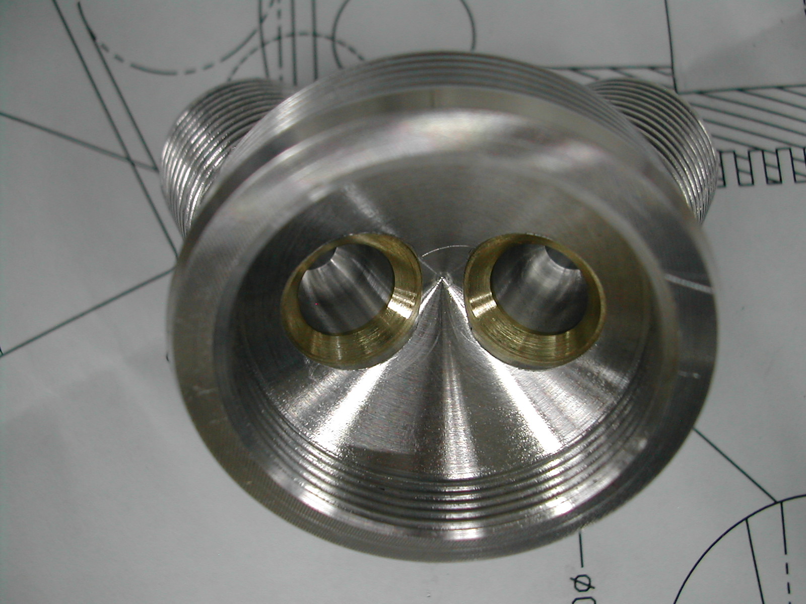
 Here’s the finished valve seat pocket.
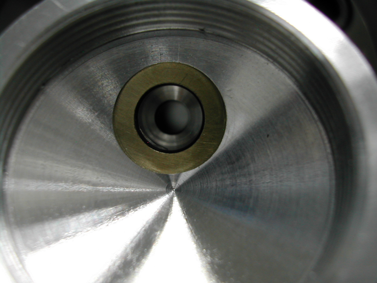 The valve seat has been swaged in place. For details of this operation, see the valve seat log.
Instead of just 0.002″ press fit as in the original design, swaging the seats in place gives a press fit on the O.D., a 0.003″ crush on the flange on the valve seat, as well as the added security of the overhang. Not only does this insure the valve seat will not fall out while the engine is running, this extra tight fit allow us to finish machine the valve seat in-place.
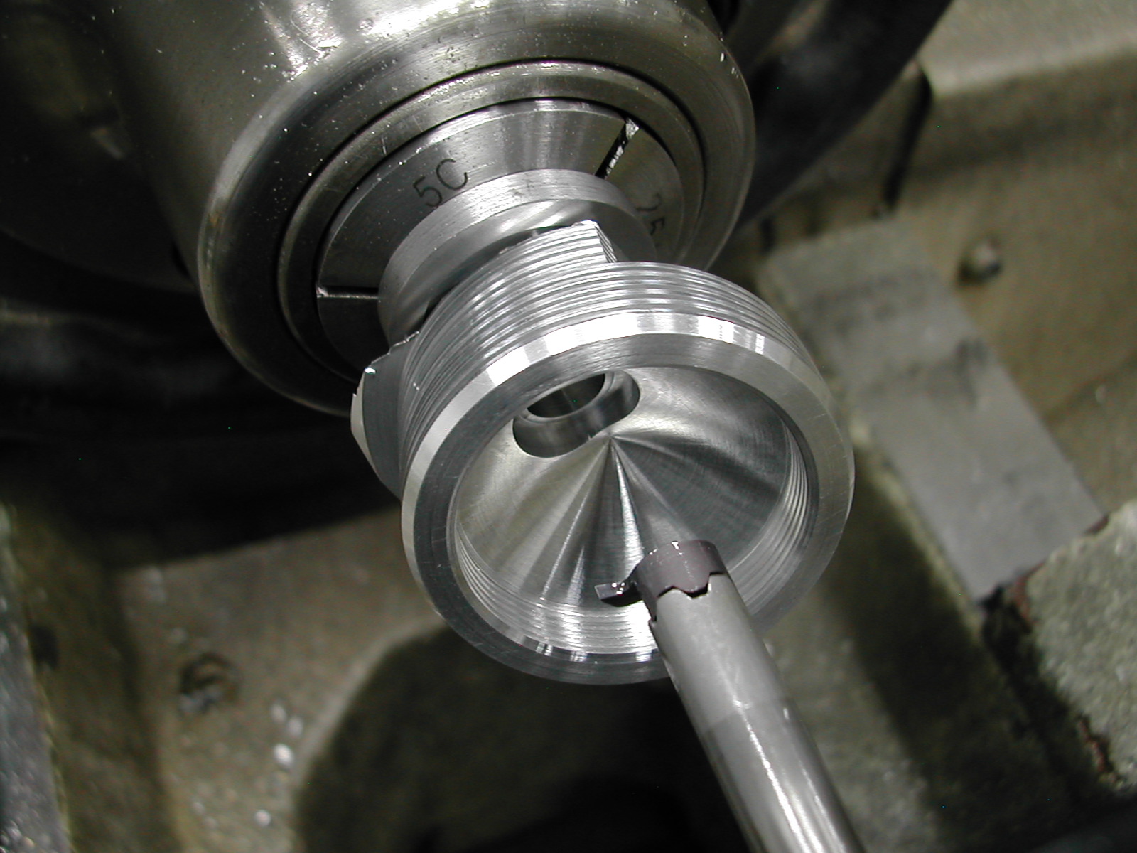
 With the seat in place, I plunged the valve plenum with a 5/16″ ball-nose endmill to 0.431″ deep. Machining both at the same time insured there is no mismatch between the two which could hinder airflow.
 The 45° angle on the valve seat was also machined in place with a 90° countersink. Once again, machining the seat in-place insures that the seating portion is concentric with the valve stem bore.
 The final step was to ream the valve stem bore to 0.1875″. Then, start the process again to finish the second valve chamber.
 One head with two valve chambers finished. Since we no longer need a flat surface on the top of the head, well add the top cooling fins next.
 Setup for the top fins starts with mounting tool CH2 to the faceplate using the end holes. The cylinder head is installed without any spacers, and aligned.
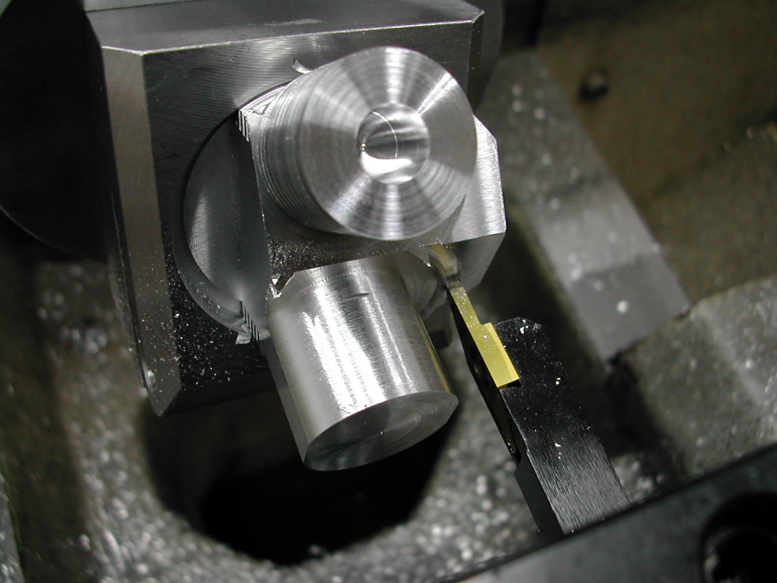
 I’ve used three tools to cut the top fins. A 3mm part-off blade and a left-hand and right-hand 0.032″ grooving tool. The X setpoint (diameter) was set for each tool on a piece of scrap before mounting tool CH2.
Here I’m setting the Y zero for the right-hand grooving tool by touching off on each of the valve towers and setting zero at the mid-point. The part-off tool and the left-hand grooving tool were set similarly.
 Using the part-off tool, I made 3 passes to take out most of the waste down to a little over the 1.437″ radius.
 With the waste gone, I then proceeded to put in the left side grooves using the right-hand tool. I used the same grooving tool to finish turn the O.D. to 1.437″ between the grooves.
 After the three left side grooves, I switched to the left-hand tool and put in the three right side grooves.
 This is the finished head at this point. There is still excess material around the sparkplug area and overhanging the lower fins on the front.
 In this photo you can see where the top grooves cut into the first lower fin on the front. This will be removed when we set up the rotary table to remove the overhang.
 With the tool set up in the mill at 25°, the head is installed with a 3/16″ spacer for milling off some of the excess material on the front. This same setup will be used to drill and tap for the sparkplug as well.
 A 3/4″ endmill makes quick work of the excess material. I’m cutting about 0.020″ below where the cutter first contacts the top of the previously turned fins.
 With the excess material removed, the next step is to centerdrill and then drill for the sparkplug.
 I’m using Rimfire VR2L plugs so I’ve tapped the hole 1/4″-32. Since it’s pretty easy to line up the cylinder heads for this operation, I’ll go ahead and drill and tap all the heads before moving on.
Don’t worry if some of the fin sections towards the front of the head break off when tapping. We’re going to remove these later on anyway.
 While I have the drill chuck in the mill, I’ll go ahead and tap the tops of the valve towers for the rocker bases. Since these are tapped 2-56, I made a small sensitive tap holder for the chuck. It’s just a piece of rod drilled for a slip fit over the tap shank. I then made a small knurled collar for turning the tap.
To use, I’ll chuck the sleeve in the drill chuck, insert the tap, and then lower the quill until the whole thing is just above the part. I then lock the quill in place and hand turn the tap into the part. The sleeve guides the tap, but lets it float axially without having to fight the quill return spring.
 I’m using a 0.327″ pin to align the valve tower for drilling the rocker base mounting holes.
 The holes are centerdrilled and then drilled with a 0.070″ bit. Make sure the holes are oriented towards the front of the cylinder head. When you spin the head around to work on the other valve tower, you’ll be putting the holes for that one in on the other side of the centerline because of this.
 Here’s a shot of the tap guide in action with the tap driven into the head. Also note that I’m now working behind center on this second valve tower.
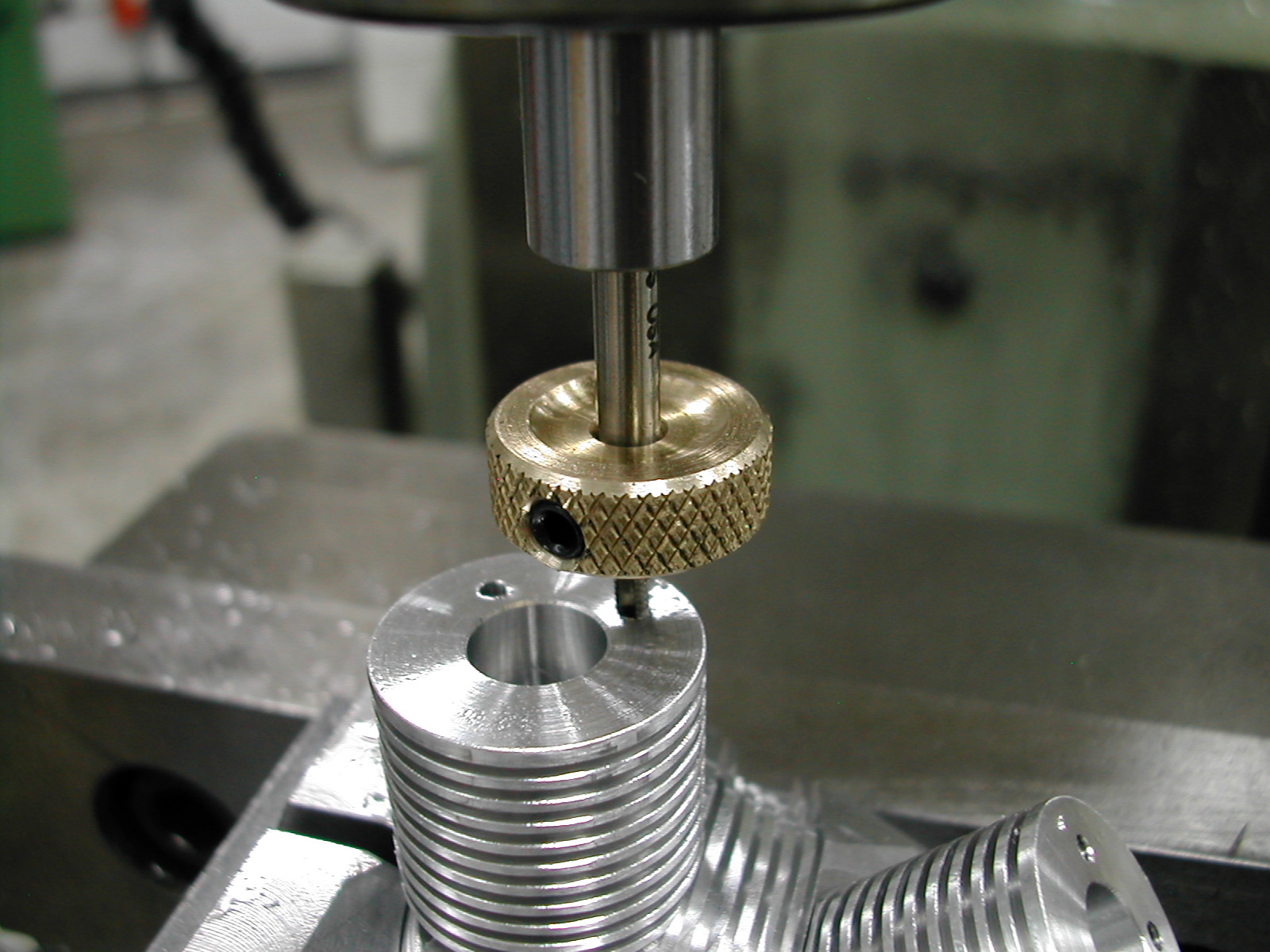
 With all the drill chuck work done on all of the heads, I switched out to a collet and I’m using a 12mm endmill with a 1mm corner radius to counterbore the spark plug well. Once I get the correct depth set on my set-up head, I’ll go ahead and counterbore all of the heads.
 Now I’ll chamfer the counterbore. Again, by doing this one operation to all the heads at the same time without changing the cutter depth, I get a consistent chamfer on all the heads.
 One last milling operation before changing back to the drill chuck. I’ve set a quill stop to control my depth as I use a 5/16″ ball-nose endmill to bore the intake and exhaust cross-holes.
 Once the intake and exhaust cross-holes are done in all the heads, I switched back to the drill chuck and put in the 6-32 tapped hole for the manifold screw.
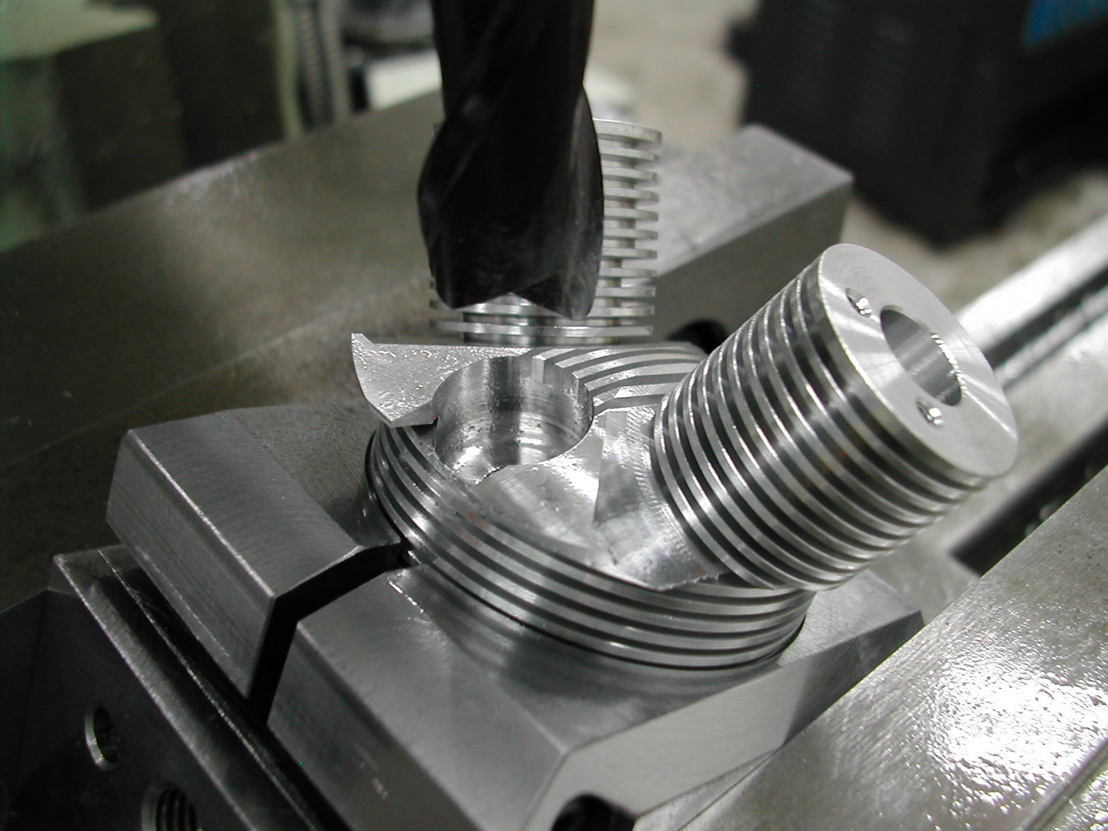
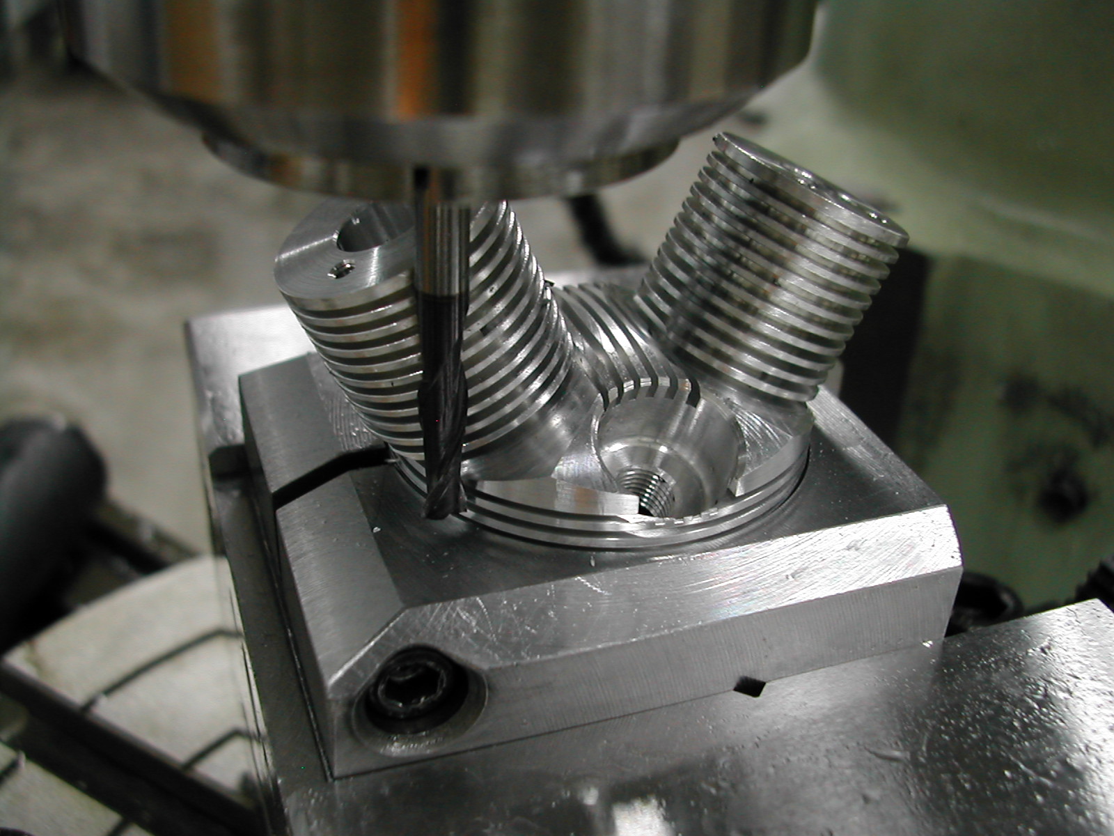 I’ve set tool CH2 up on the rotary table with a 3/16″ shim and I’m using a 4mm endmill to remove the overhanging material from the front.
I took my time setting up tool CH2 on the rotary table for this job. Not only did I center it, but I also aligned it to the 0.00° mark so I could also do the milling operation below on each head while the part was still clamped.
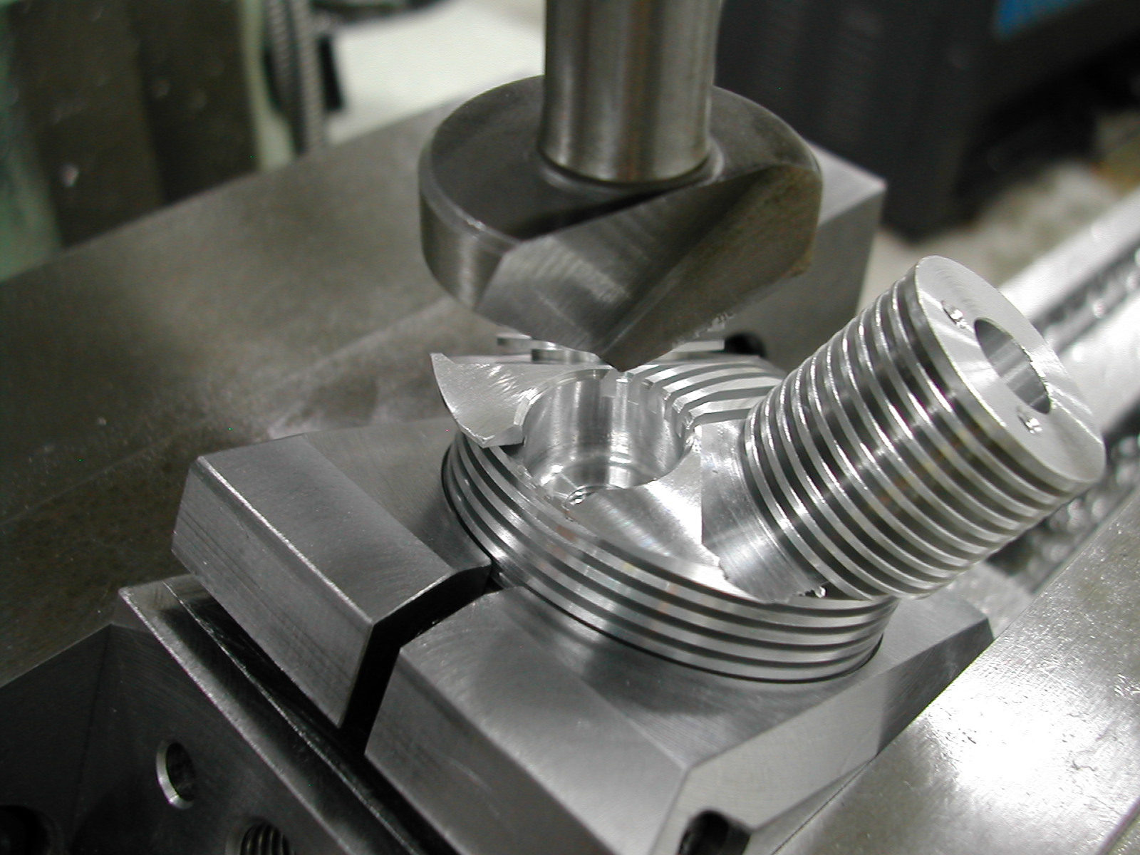
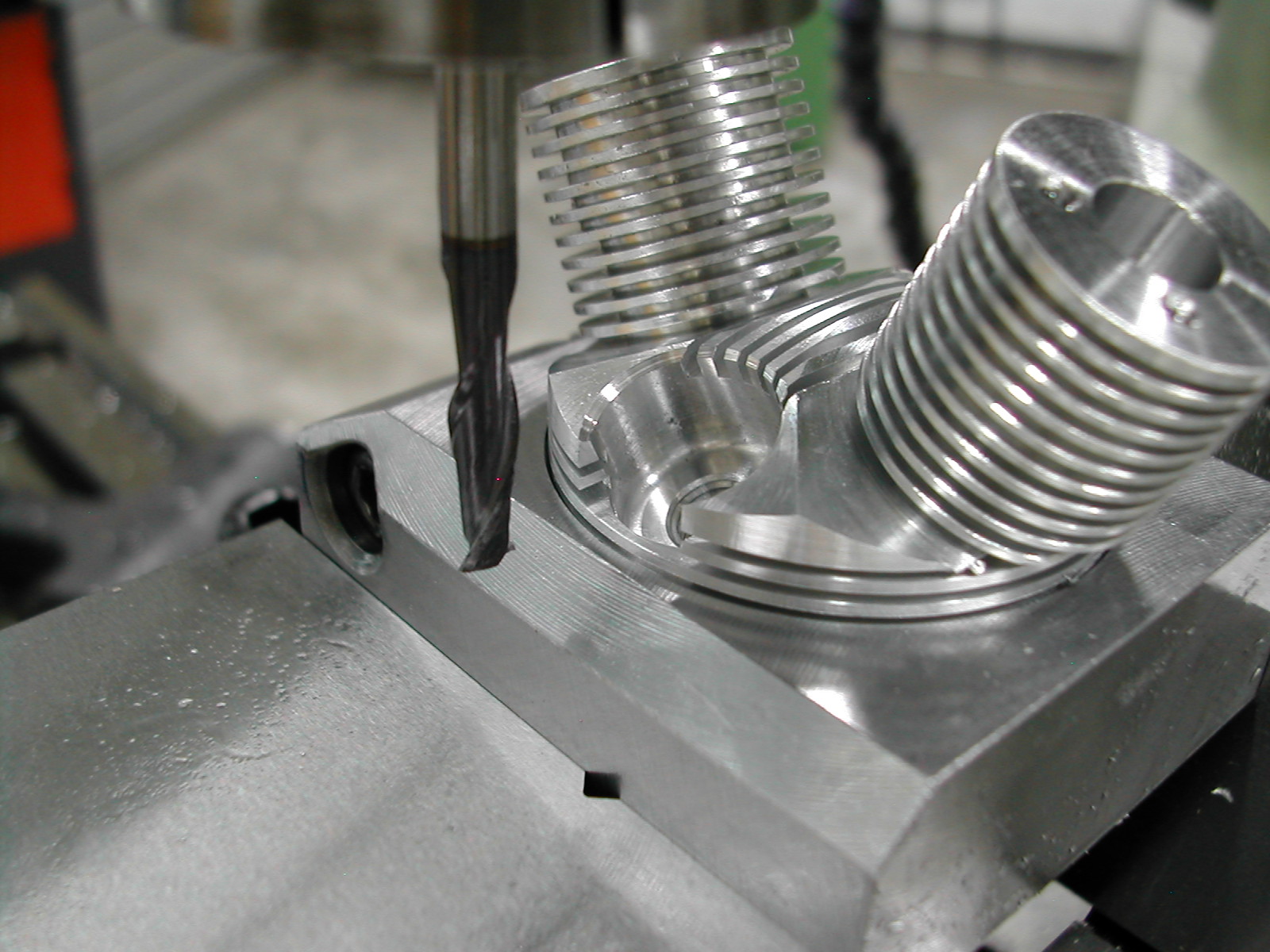 While the head was still clamped for removing the overhand, I locked the rotary table at 0.00° and offset the mill side-to-side in X to mill off the uppermost fin where it was notched putting in the top cooling fins.
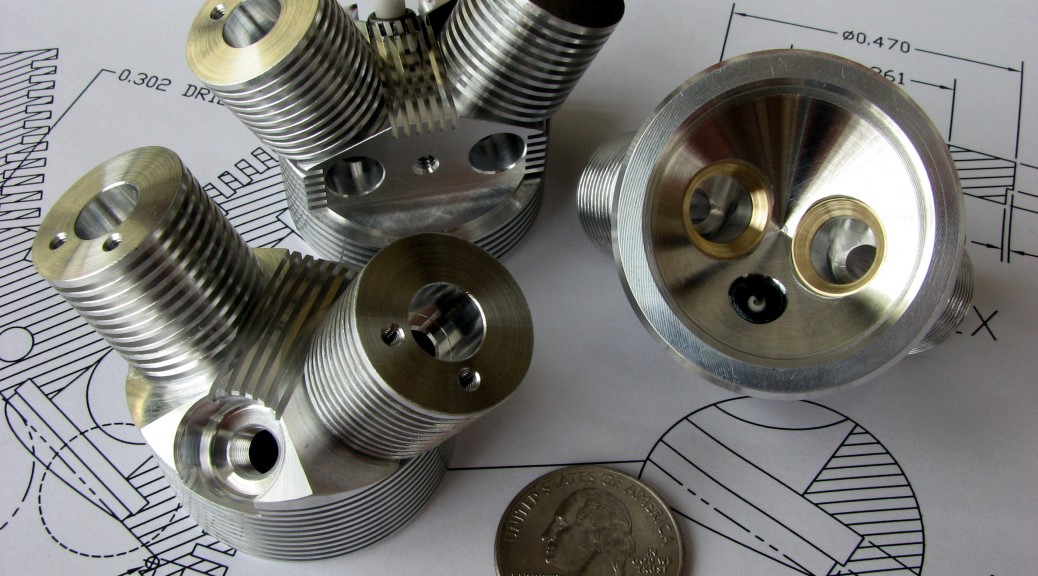
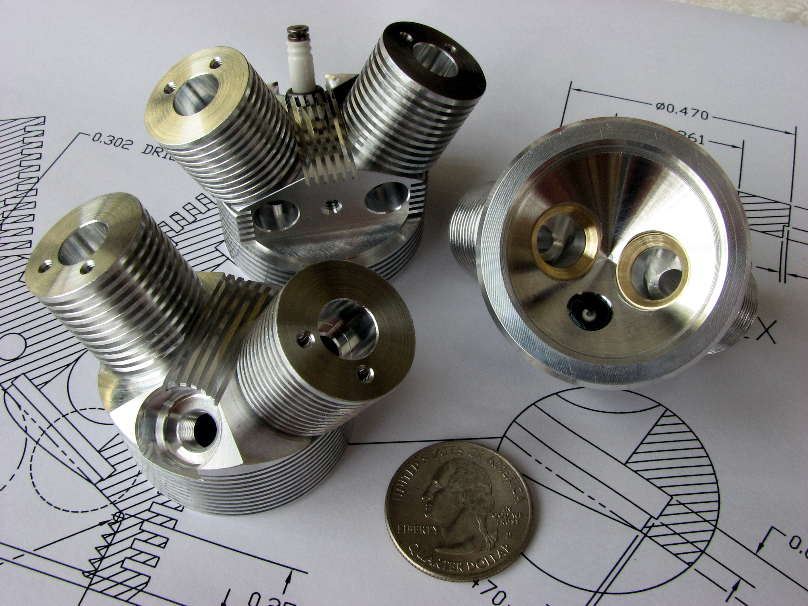
I started with 11 blocks and I ended up with 11 good finished heads so I’ve already got a head start (no pun intended) on the 18 cylinder radial. The Rimfire plugs look great in these heads.
- Block starting weight: 350.76g
- Head finish weight: 59.30g
- 83% of the material converted into chips!
Disclaimer and License
All material, including the CAD drawings, relating to the construction of the Hodgson Radial presented on this site is free to use any way you see fit. However, no guarantees are made regarding the accuracy or correctness of the material presented here.
Links Used On This Page
(CAD drawings are in AutoCAD 2010 Format)