
 Well, it would have been nice if I could have found some soft 1000-series aluminum here in China so I could just turn and part off these rings from some round stock, but that turned out to be impossible. I ended up purchasing some 0.032″ 1100 aluminum sheet. 1100 alloy is essentially pure aluminum and the 12″ x 12″ sheet I ordered from McMaster (p/n 2471T11) was in the “0” (Annealed) condition – perfect for a head gasket.
The only problem with a sheet of 0.032″ 1100-TO is how to process the flimsy, gummy material. First, I considered making a punch to stamp out the necessary rings, but I was unsure how to deburr the stamped parts. My second thought of processing a stack by drilling, boring, and turning seemed to work out okay. Below is the process I used to make these gaskets.
 I started by using a hobby knife and a straight edge to cut 1-5/8″ squares out of the aluminum sheet. I could get 7 blanks out of the width of the sheet, so I cut two rows of blanks for a total of 14 gaskets.
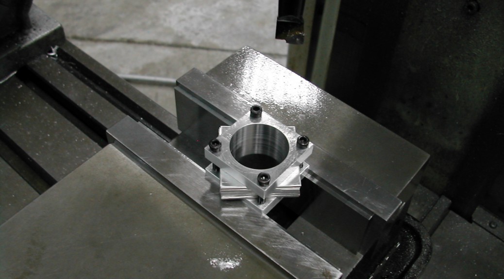
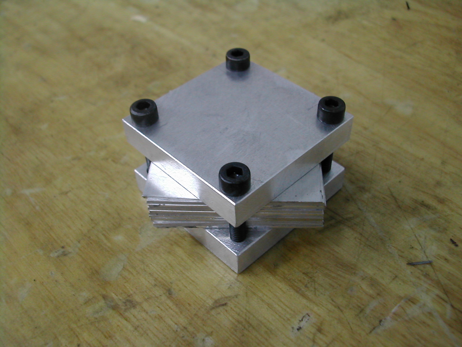
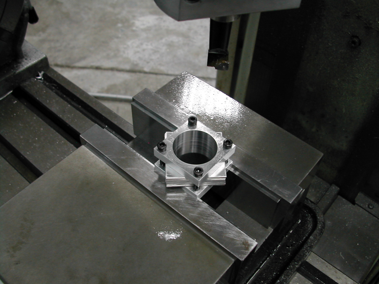
The blanks were then clamped between two 1-5/8″ squares of 6mm aluminum scrap I had laying around. Here’s my 057 Head Gasket drawing (AutoCAD 2010) which I used to lay out the clamps.
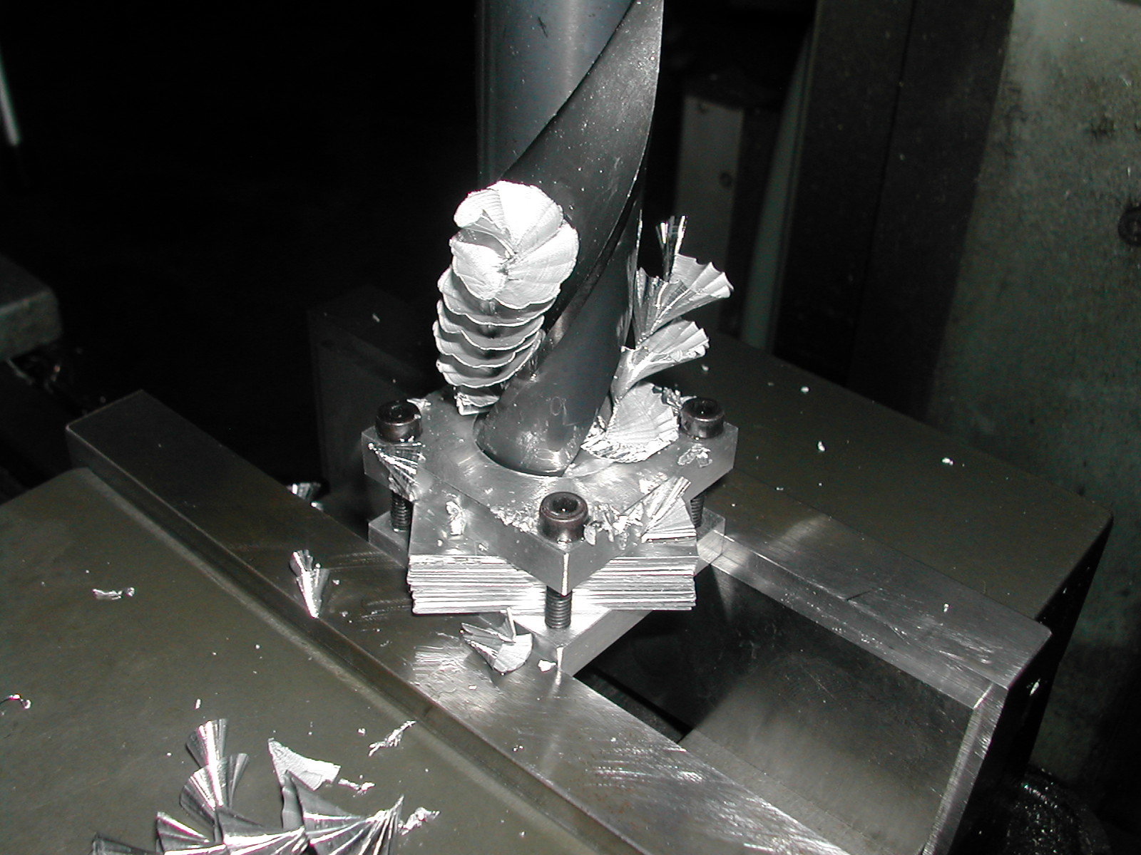 I clamped the works up in the mill and drilled a 24mm hole centered in the stack.
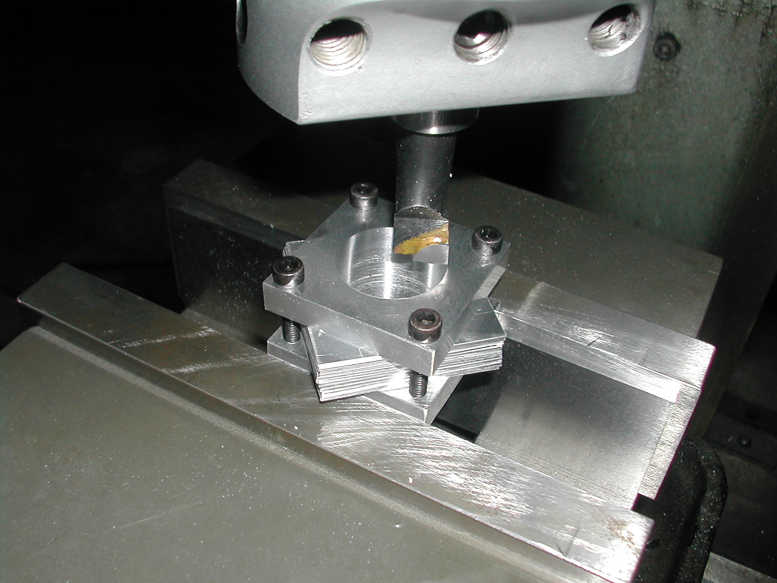 Here I’m opening the hole up in the mill with a boring head to the 1.255″ finish I.D. dimension.
 The finished I.D. The difference in cutting the heat-treated end plates versus the soft head gasket material was very noticeable and took a little bit of work with the boring bar geometry as well as speeds and feeds to get an acceptable surface finish.
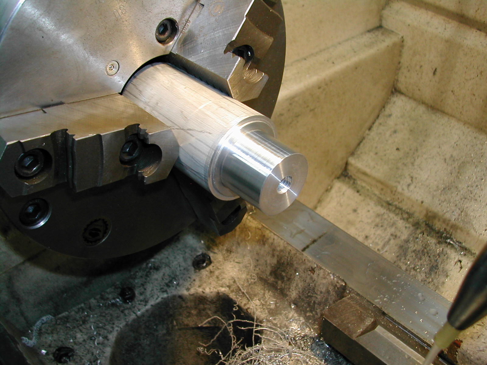 With the blanks bored out, the next step was to turn an arbor in the lathe to hold the stack. A scrap piece of aluminum bar chucked and the end was threaded for an M8 SHCS. This threaded hole was then counterbored 8mm in diameter about 7mm deep. The O.D. was then turned was turned down to 1.50″ for about 7mm. This turned down end was then parted off to make a 5mm thick clamping washer.
The material left in the lathe was then turned to the 1.254″ diameter about 0.050″ shorter than the thickness of the gasket stack and end plates.
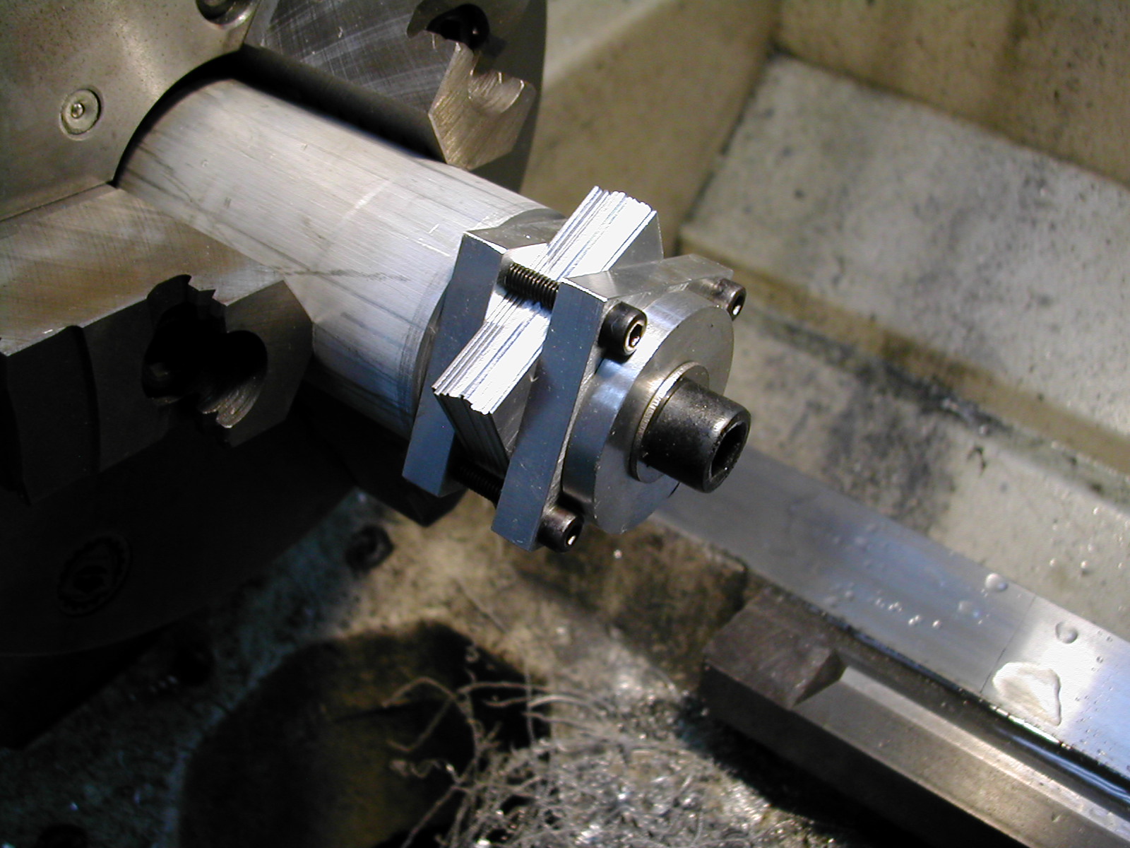 Without loosening the M4 clamping screws holding the stack together, it was moved from the mill and clamped on the freshly turned arbor. Once the M8 SHCS was securely tightened, the four M4 SHCSs were removed from the stack.
 This shot shows the stack turned to the finish 1.375″ O.D. If you look closely just to the right of center in the turned down area, you can see the stack of 1100 aluminum gaskets. Once again, it took a little work with speeds, feeds, and cutting tool geometry to get an acceptable surface finish on this soft material.
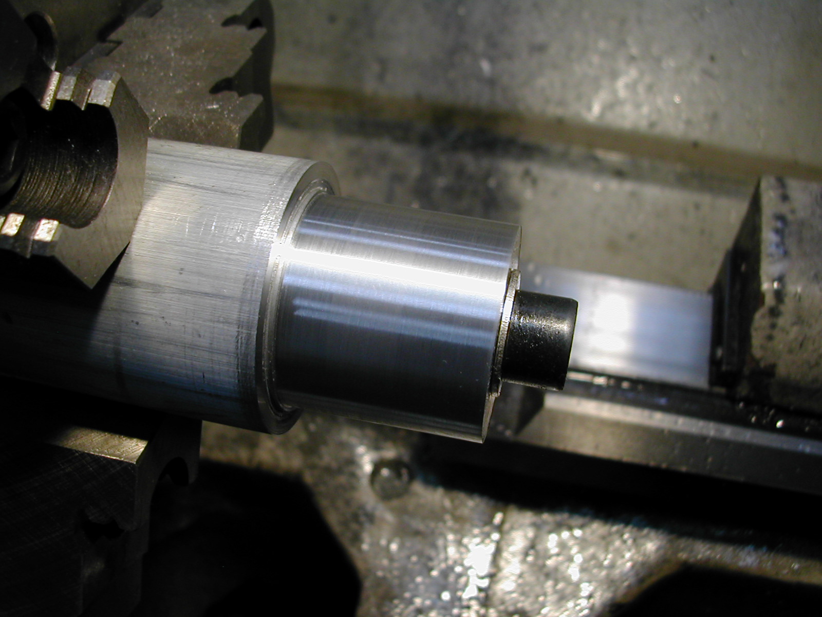
 Here the M8 SHCS has been removed and the gaskets are being taken off of the arbor.
The finished gaskets and what is left of the two 1-5/8″ square clamping plates. By boring the I.D. and turning the O.D. while the stack was clamped together between cauls, the resulting parts were completely burr free.
Disclaimer and License
All material, including the CAD drawings, relating to the construction of the Hodgson Radial presented on this site is free to use any way you see fit. However, no guarantees are made regarding the accuracy or correctness of the material presented here.
Links Used On This Page
(CAD drawings are in AutoCAD 2010 Format)