
- Hodgson Part 065, Rocker Bases
- Hodgson Part 066, Rocker Arms
- Hodgson Part 067, Rocker Pivots
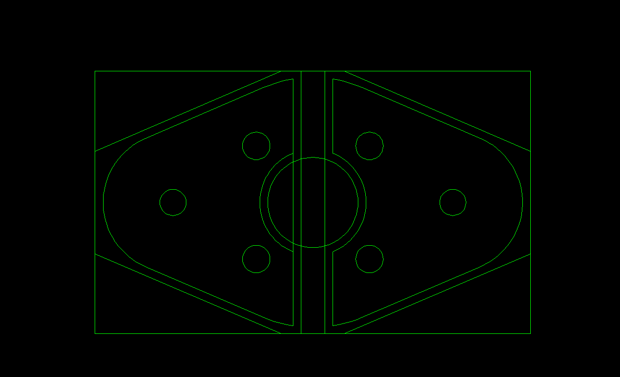
 The bases are fairly small parts, so I’ve attempted to work in as many pieces as I can at one time. The CAD file 065 Base Setup (AutoCAD 2010) includes my layout as well as some other layers with sketches of the milling and turning fixtures I made as well.
 The rocker bases began life as 3 pieces, 1.1″x3.0″, sawn from 24mm thick Aluminum 7075-T6 plate. Each one of these pieces will make 8 rocker bases.
 In the mill, I faced the four sides of each piece to 1.000″x0.820″.
The three pieces were then sawn in half along the long dimension and then the ends were squared in the mill to the 1.360″ stock length.
 Each of these six blocks will make four rocker bases.
 I began by center drilling the rocker pivot holes on the 1.000″ wide block faces. One hole was spotted then the part was rotated and the second hole spotted. Then the part was flipped and the two remaining pivot holes were spotted. This was repeated for the other 5 blocks.
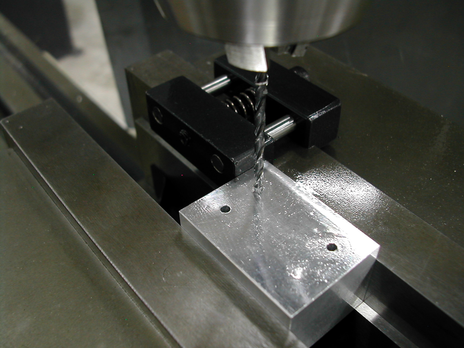 With the 6 blocks all center drilled, the four holes in each block were then drilled using the same drill, rotate, drill, flip, drill, rotate, and drill process as the spotting operation.
After drilling all 6 blocks, this process was repeated to ream the holes with a 2.4mm (0.945″) reamer, or you could use a 0.001″ over Imperial reamer depending on which was more readily available.
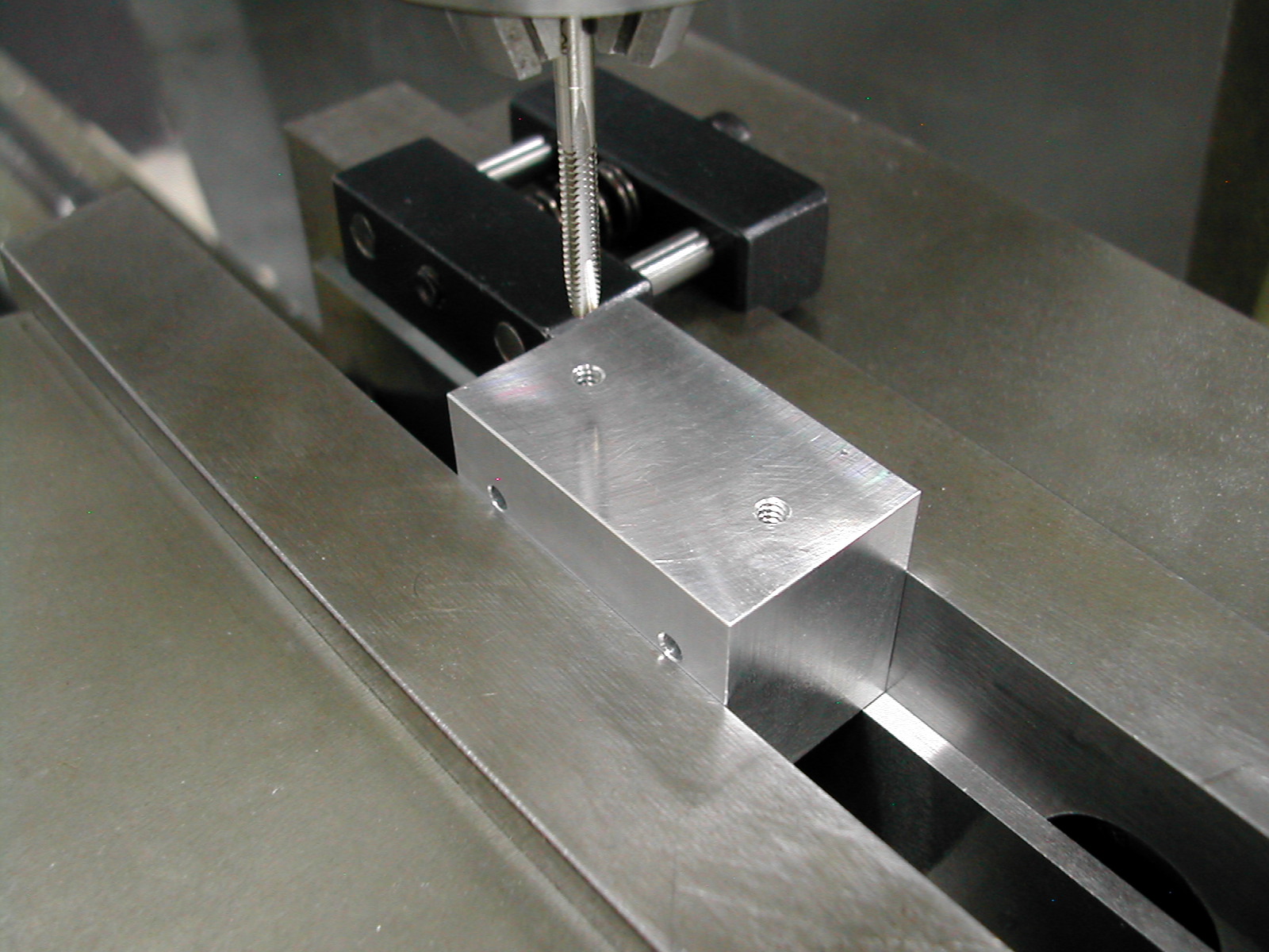 Now working with the 0.820″ wide sides, I began by putting in the #4-40 threaded fixturing holes. These were drilled and tapped until they intersected the previously finished pivot pin holes.
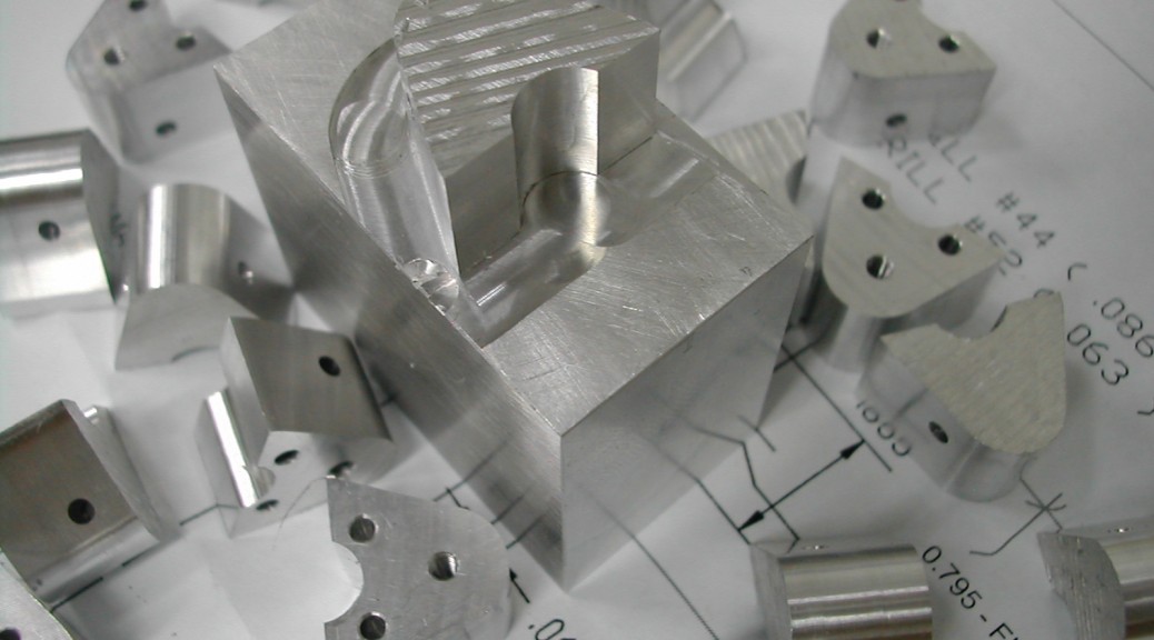
 Next the upper #44 (0.086″) clearance hole for the #2-56 fasteners were center drilled, drilled and reamed approximately 1/4″ deep following the same “production” process as the previous holes.
I reamed these holes because I will be using them as locating/drive holes in conjunction with my milling and turning fixtures.
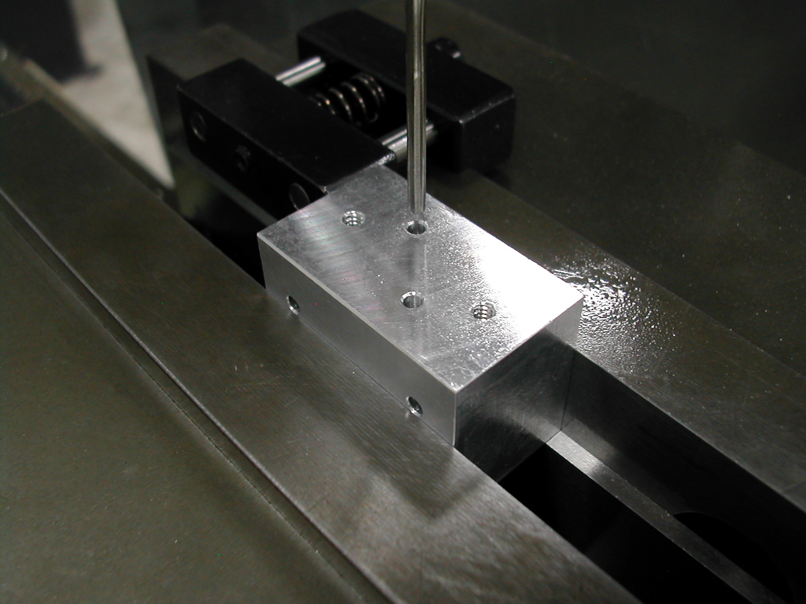
 With the upper screw clearance holes completed in each block, the four lower clearance holes were added.
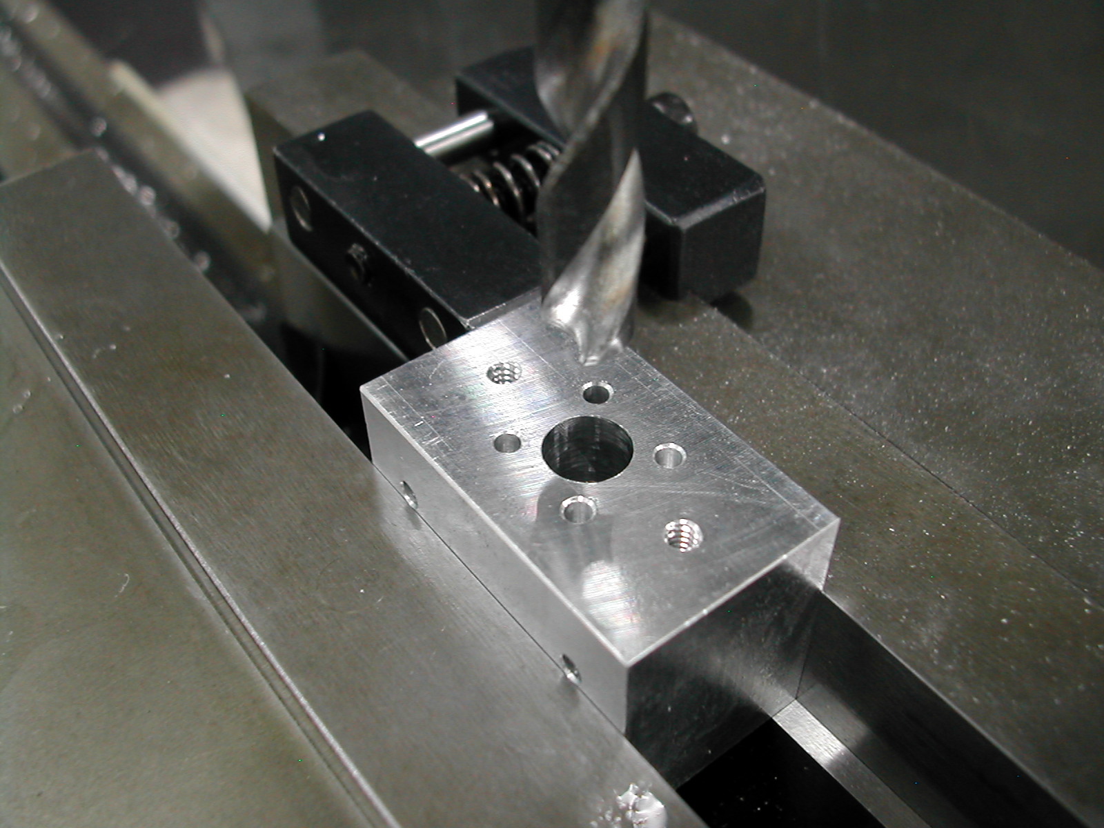 Finally a 9/32″ hole was drilled through the center of each block. This hole just roughs out the valve clearance leaving about 0.025″ stock so there was no need to do this from each side of the blocks.
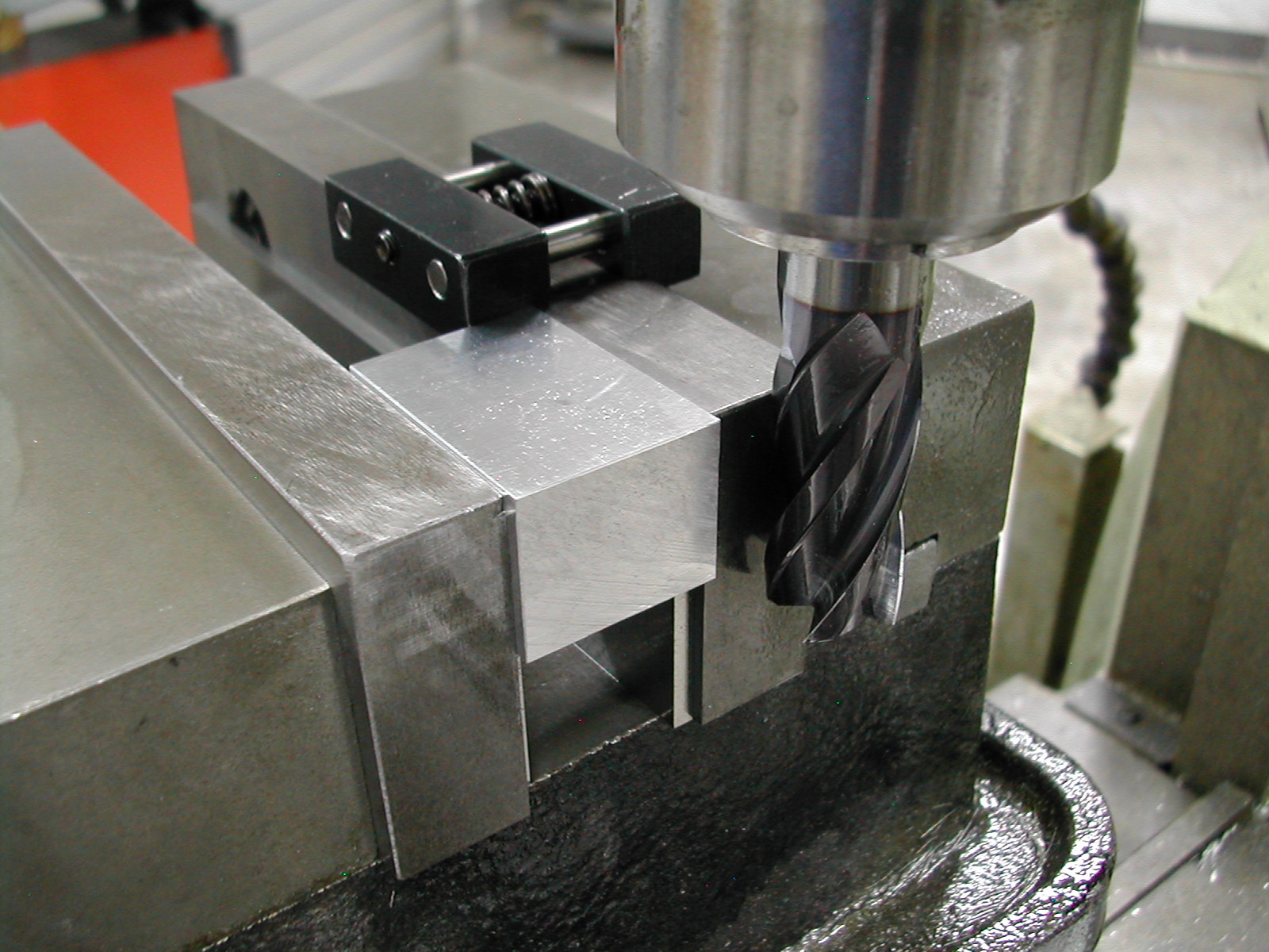
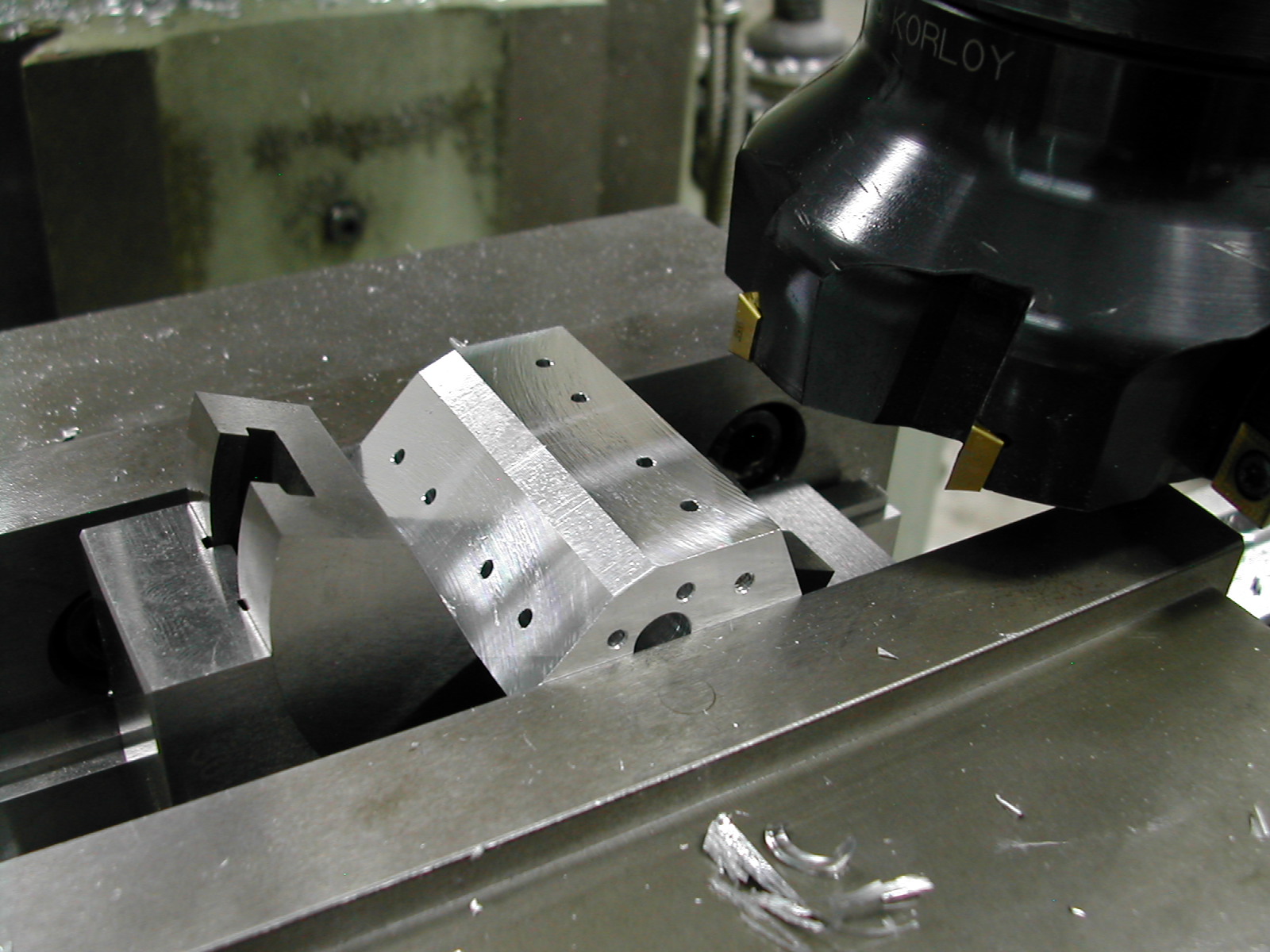
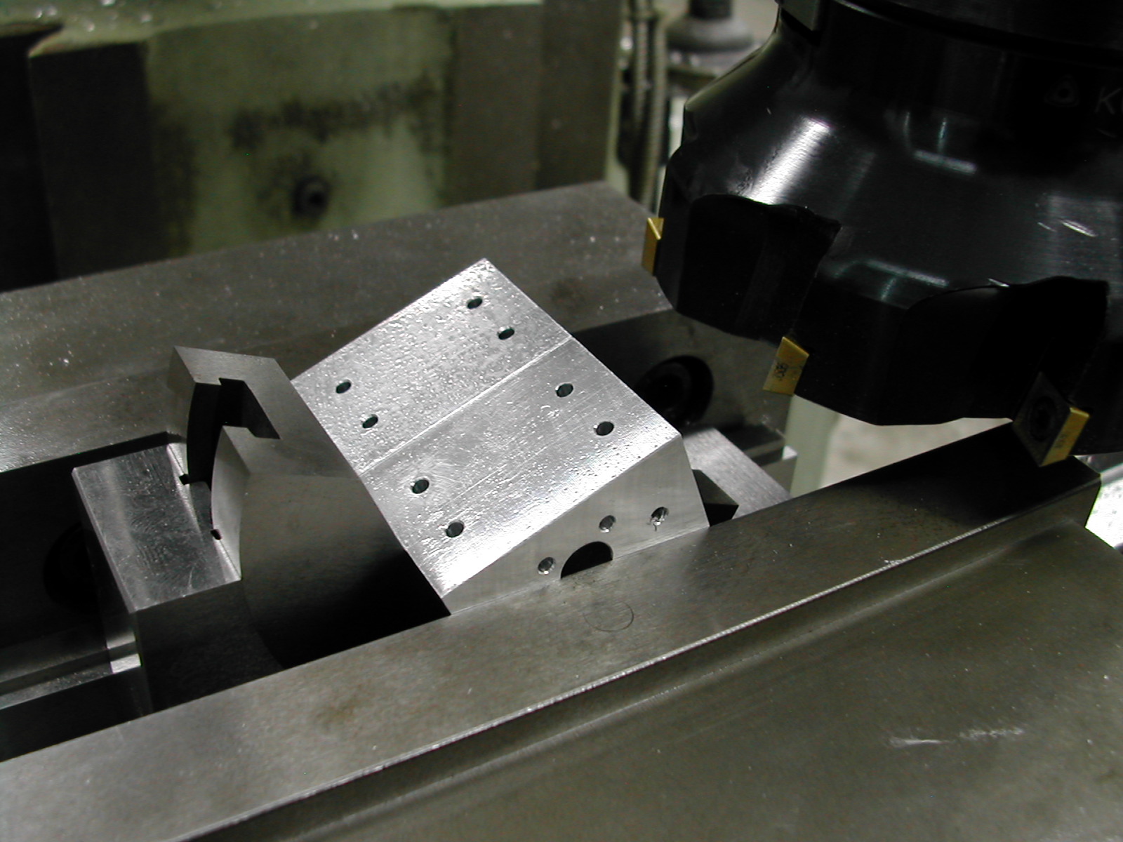 Some additional roughing was done to each of the blocks by knocking off the corners at a 23.25° angle. Since my small protractor fixture was the same width as the block, I went ahead and milled two blocks at a time.
 Here’s the first corner removed from the 1.000″ wide face.
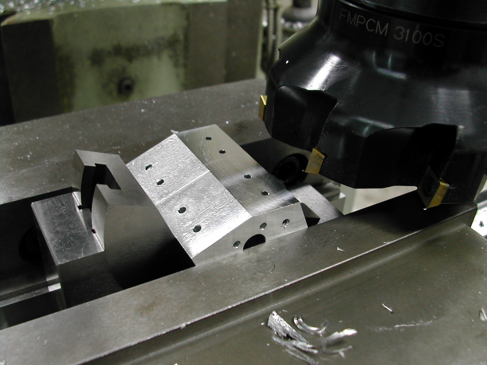
 The parts are flipped in the protractor fixture and the second corner is removed.
 If the cutter height is set to about 0.210″ below the point the cutter first touches the block’s corner, you’ll leave about 0.025″ stock to profile later.
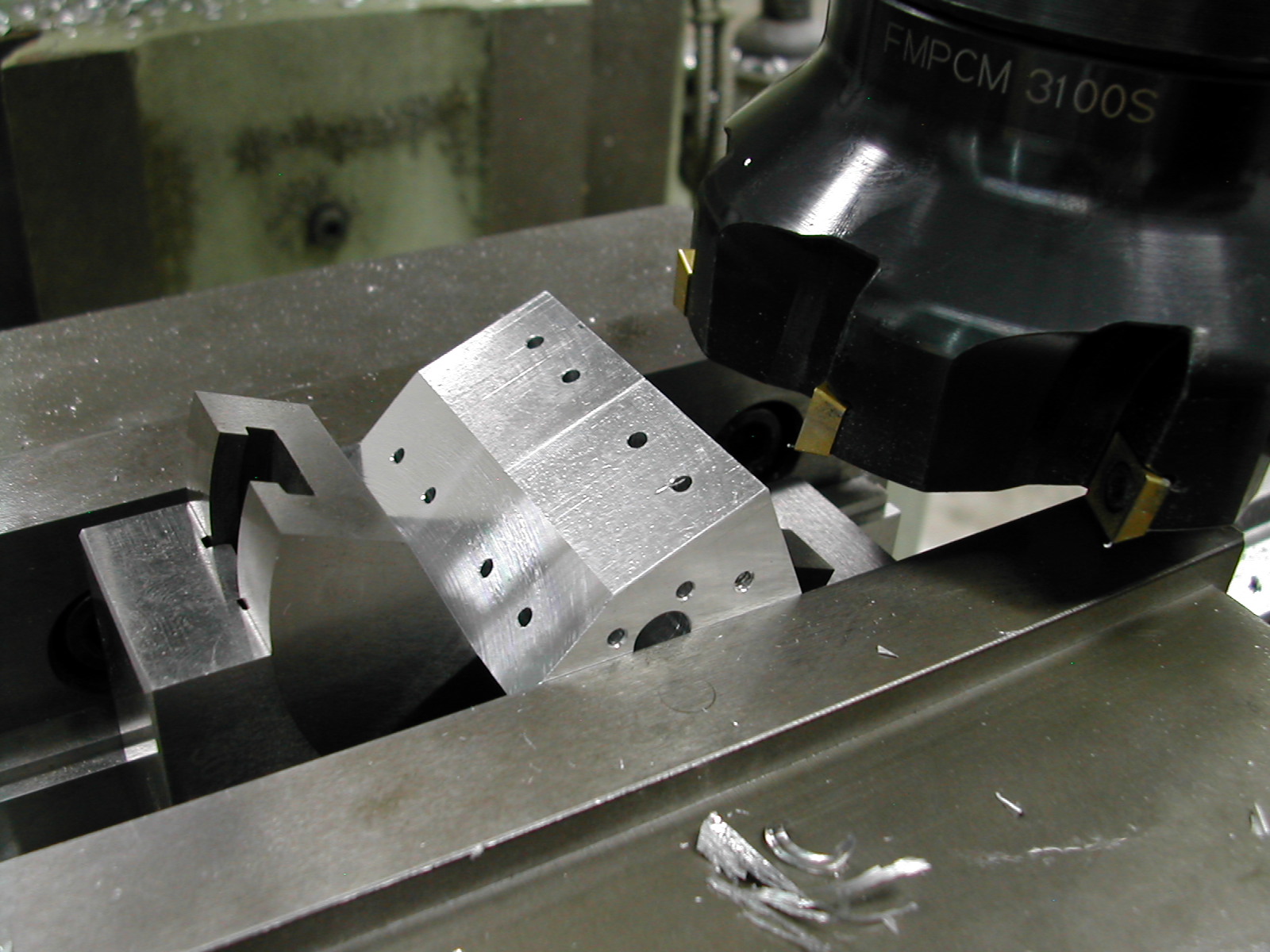
 The remaining two corners are parallel to the previous ones, so we can dispense with the protractor and work the remaining two sides with the parts clamped in the vise on parallels.
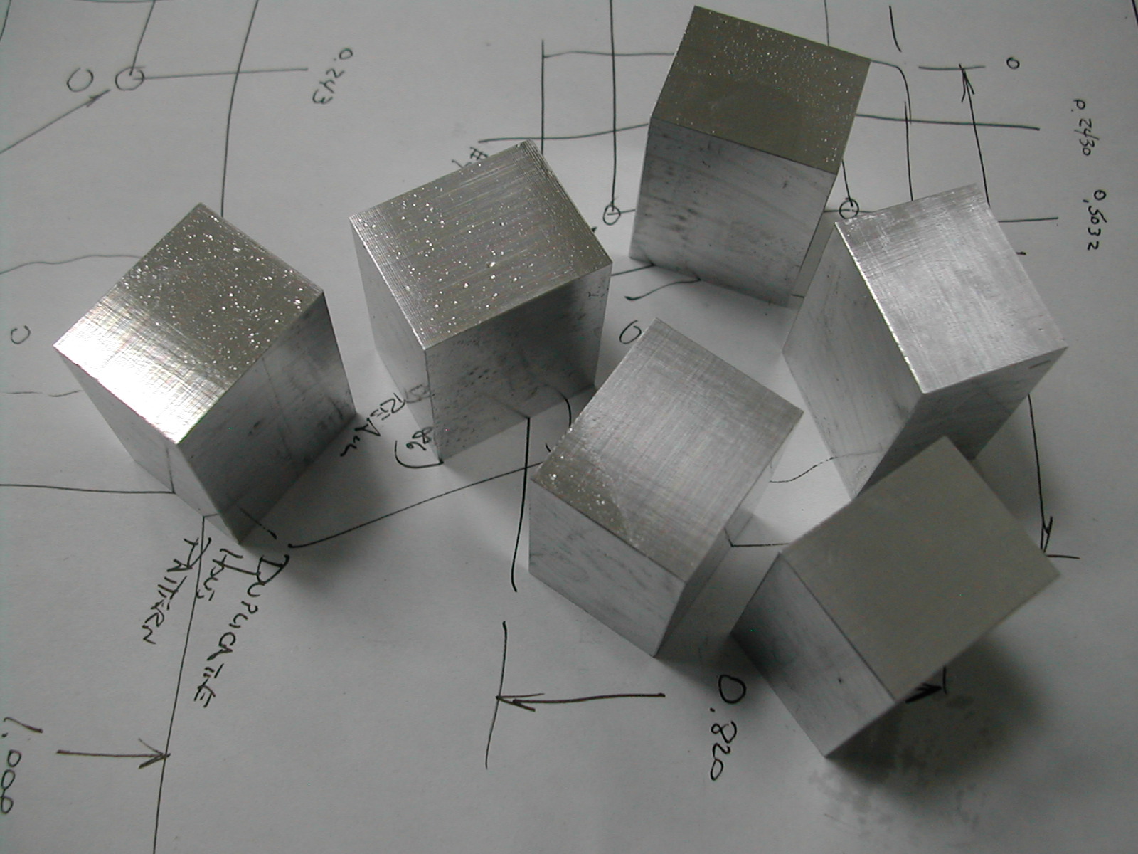
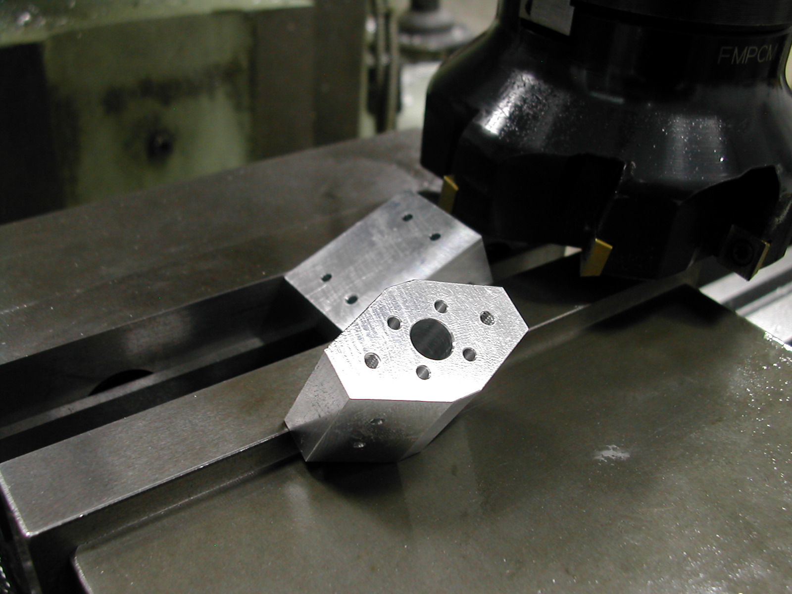
 At this point, you should have six little diamonds, each making four rocker bases.
 After a trip to the saw splitting each block crosswise and then lengthwise, you should have 24 rocker base blanks.
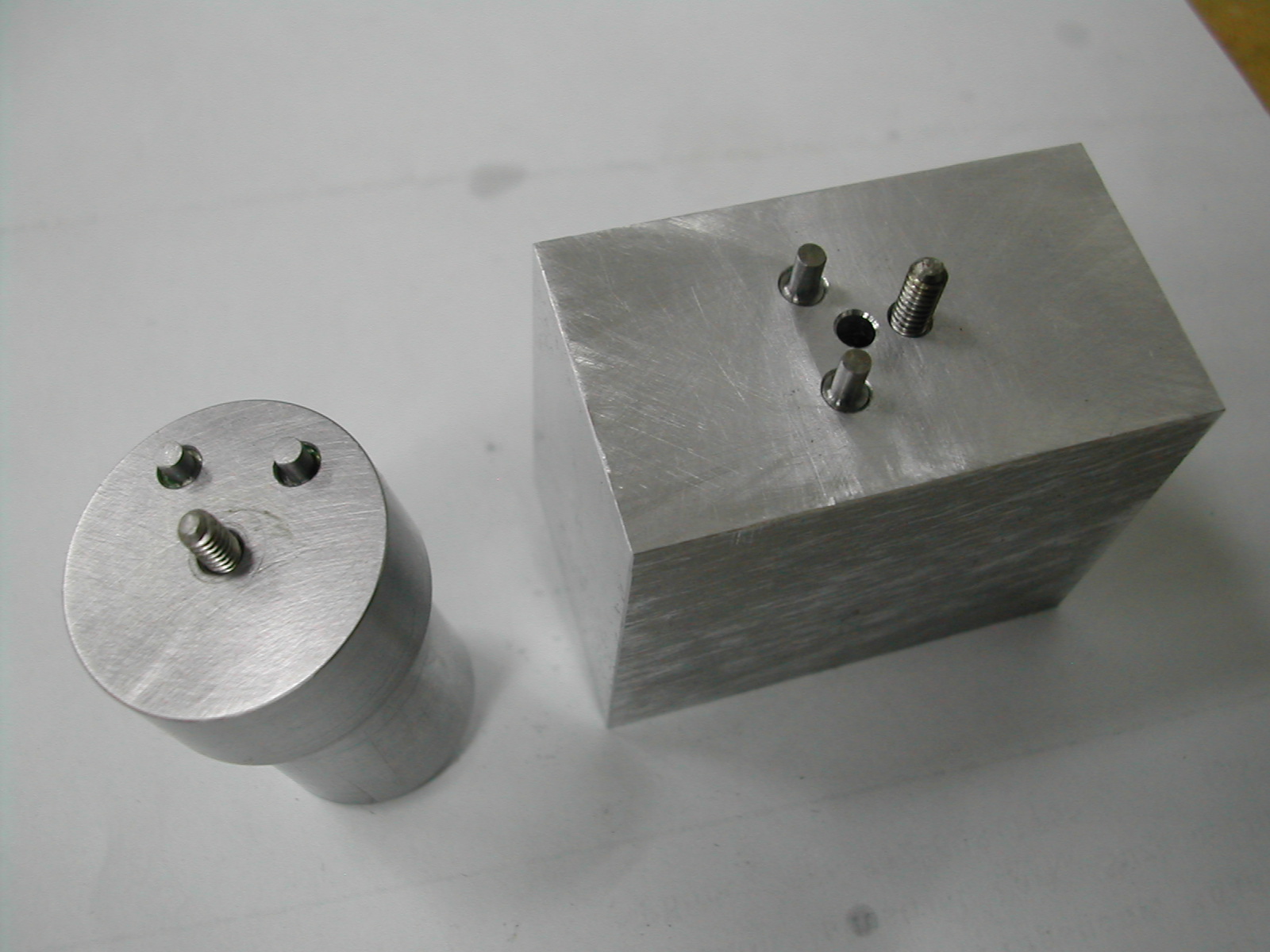 Here are the two machining fixtures I have created. The round one is a turning fixture not unlike the one presented in the plans. I have also made a rectangular fixture which I will use to profile the bases on a CNC mill when I can beg/borrow/steal some time on one. The 0.0855″ diameter pins are made by grinding down the ends of 1/8″ dowel pins.
The bottom of the rectangular milling fixture is a copy of the top only the pins have been replaced with #2-56 tapped holes. Once the blocks have been profiled and then turned in the lathe, I will mount them to the other side of the fixture using two #2-56 screws in addition to the #4-40 screw while I machine the slot for the rocker arm.
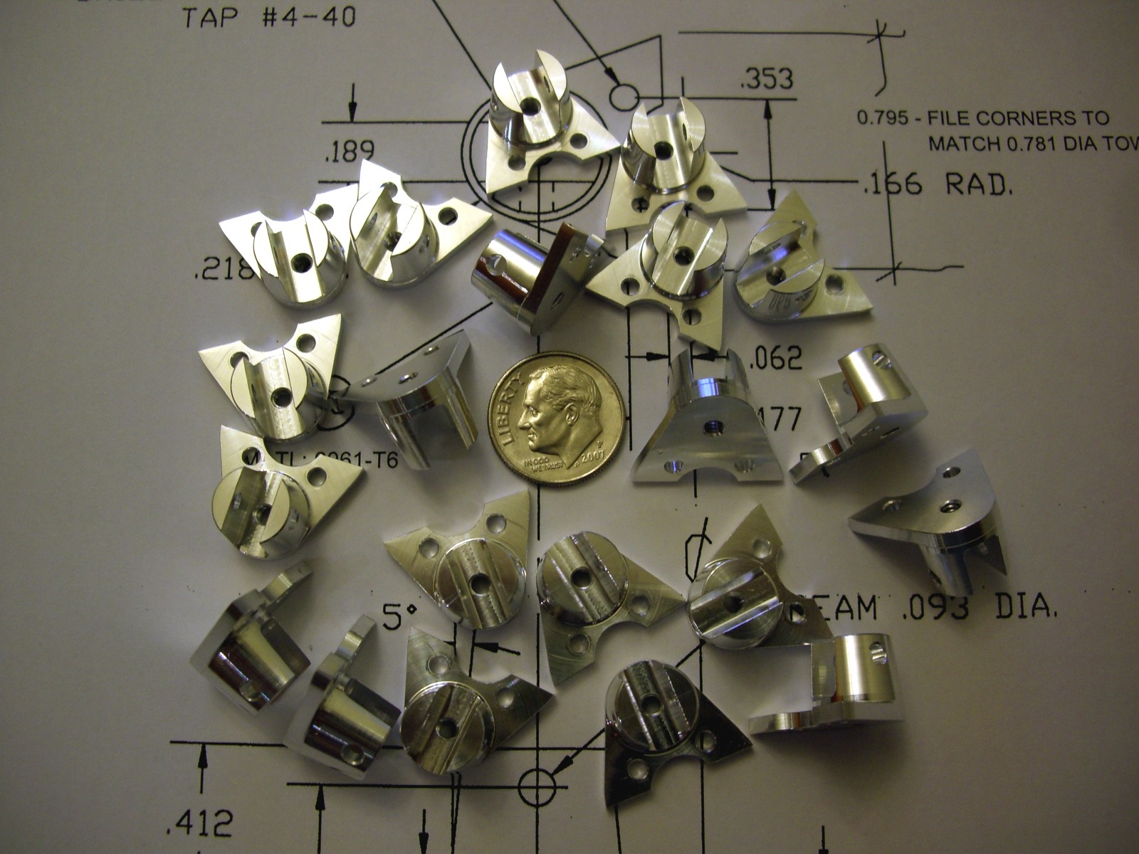
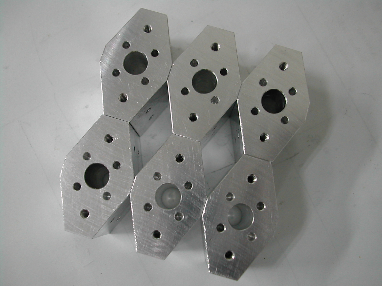
 After 3 hours and $60 worth of CNC mill time, I now have 23 profiled rocker bases. Somehow, I messed up one of the #2-56 clearance holes on one of the blanks and it would not fit on the milling fixture. Well, that’s why we make extras. Right?
 Here’s how the blanks fit on the turning fixture.
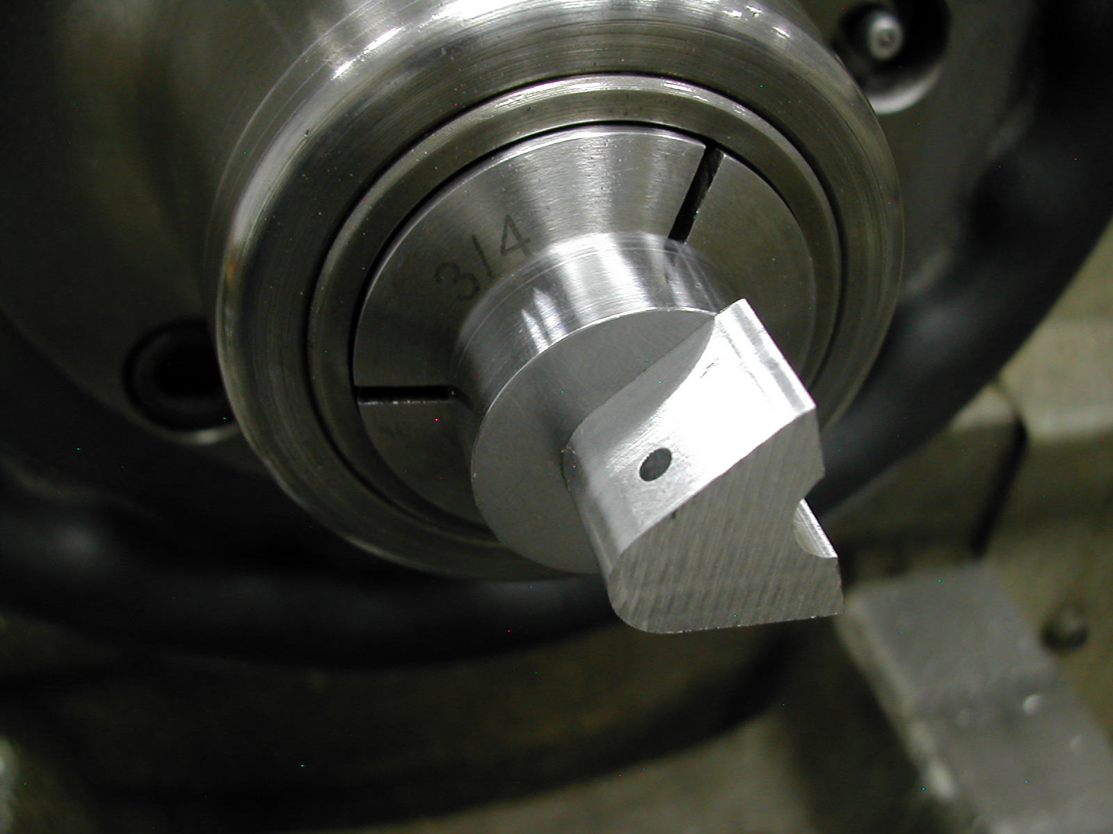
 And this is how I modified a 3/4″ collet for use with the fixture. I ground the front of the collet just a little to provide a more suitable locating surface for the fixture.
 With the fixture and blank mounted, I touched off a standard TNMG insert to the face of the fixture and also to the machined radius on the back side of the blank.
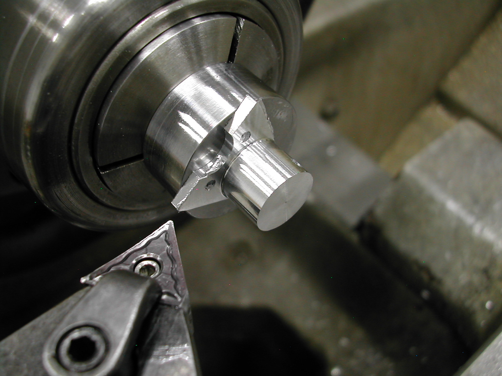
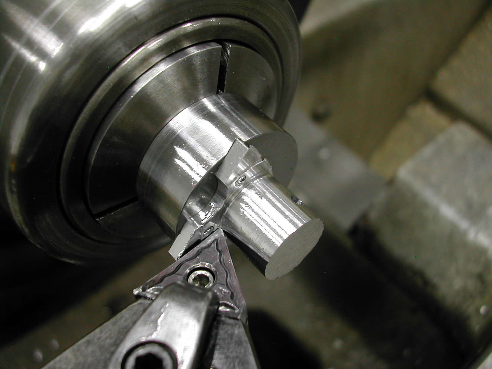 With the tool zeros set, I proceeded to rough out the part. First with three cuts fed in from the end down to 0.085″ from the fixture, the last being about 0.005″ larger than the finished diameter.
 Then with three more cuts fed from the end to 0.418″.
 The finish pass started where I finished the roughing cuts. On the last pass feeding in from the end, I went all the way to 0.412″, faced out to 0.436″ diameter, fed left to 0.080″ and then faced out to clean up the legs.
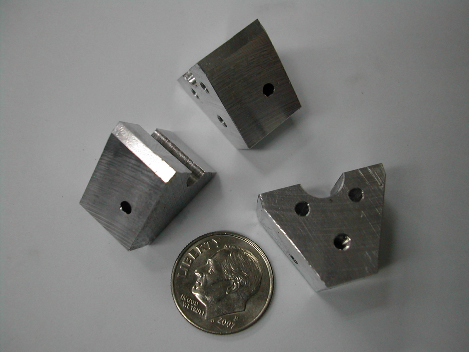
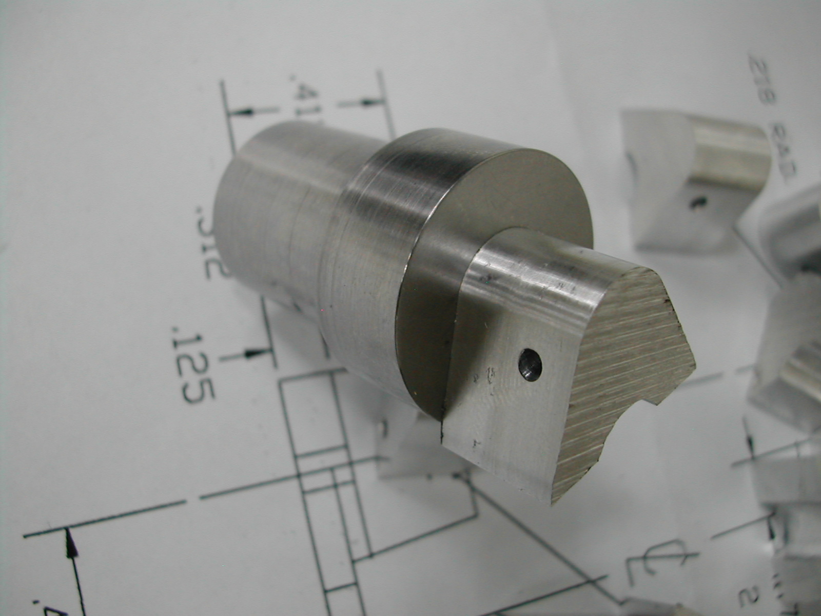
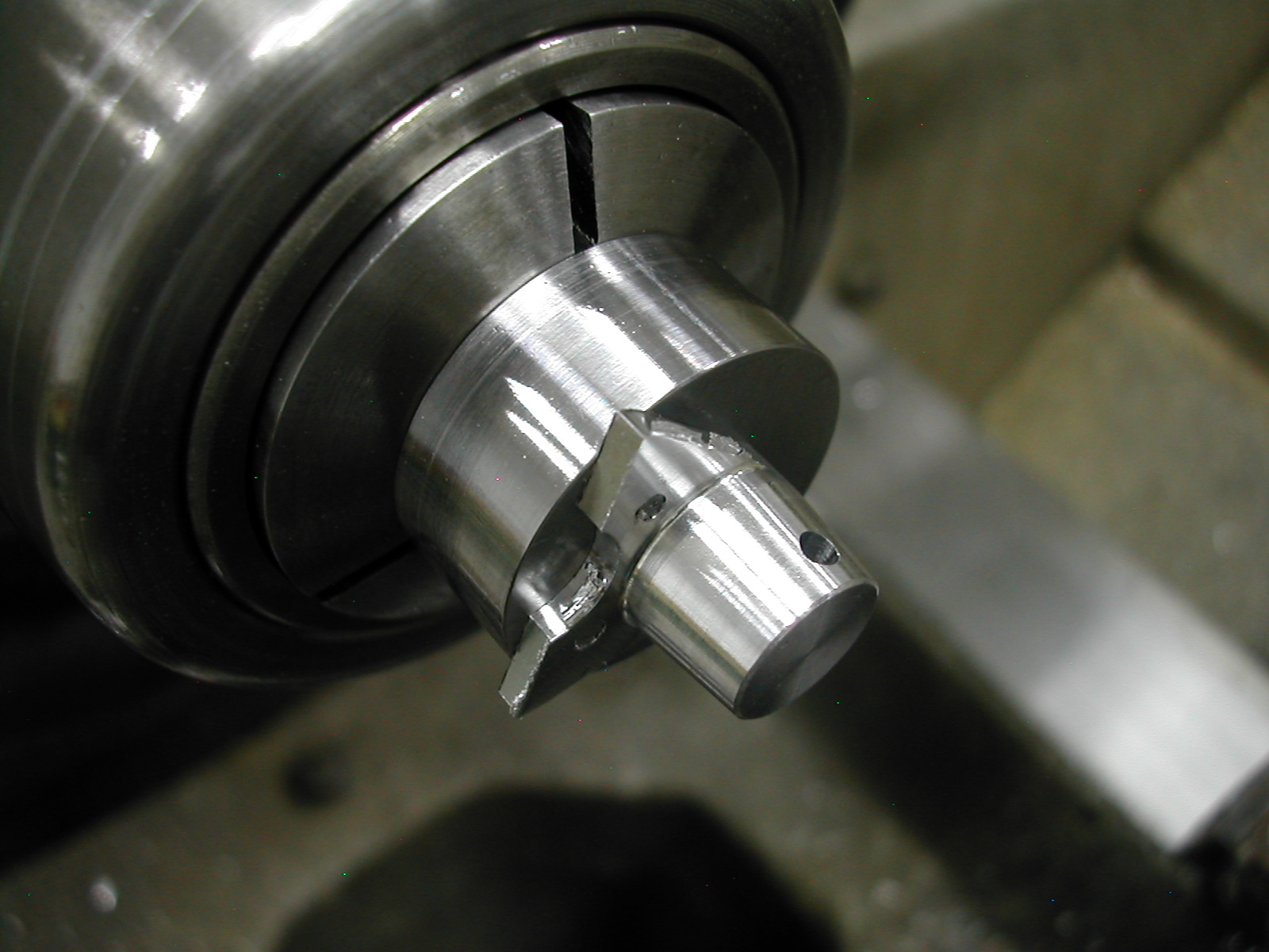 The last part was to turn the 5° taper and file a slight radius on the end.
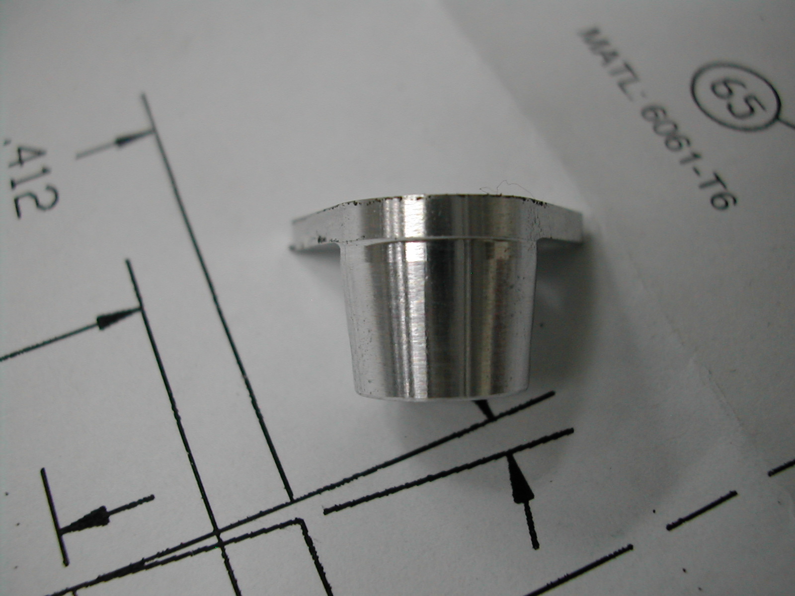 When I ran the first part, I turned the boss to 0.436″ to match the 0.218″ radius I previously milled. Because of the various fixtures used and the clearance between the various pins/screws/holes I had about 0.001″ mismatch between the two. This was very obvious where the 5° angle intersected – a nice crisp intersection on one side and a upward curving intersection on the other.
To correct this, I chose to turn the boss at 0.432″ diameter which resulted in a nice crisp line between the boss and the 5° taper. Now that I’ve done it this way, I personally like the resulting little step that separates the boss from the base.
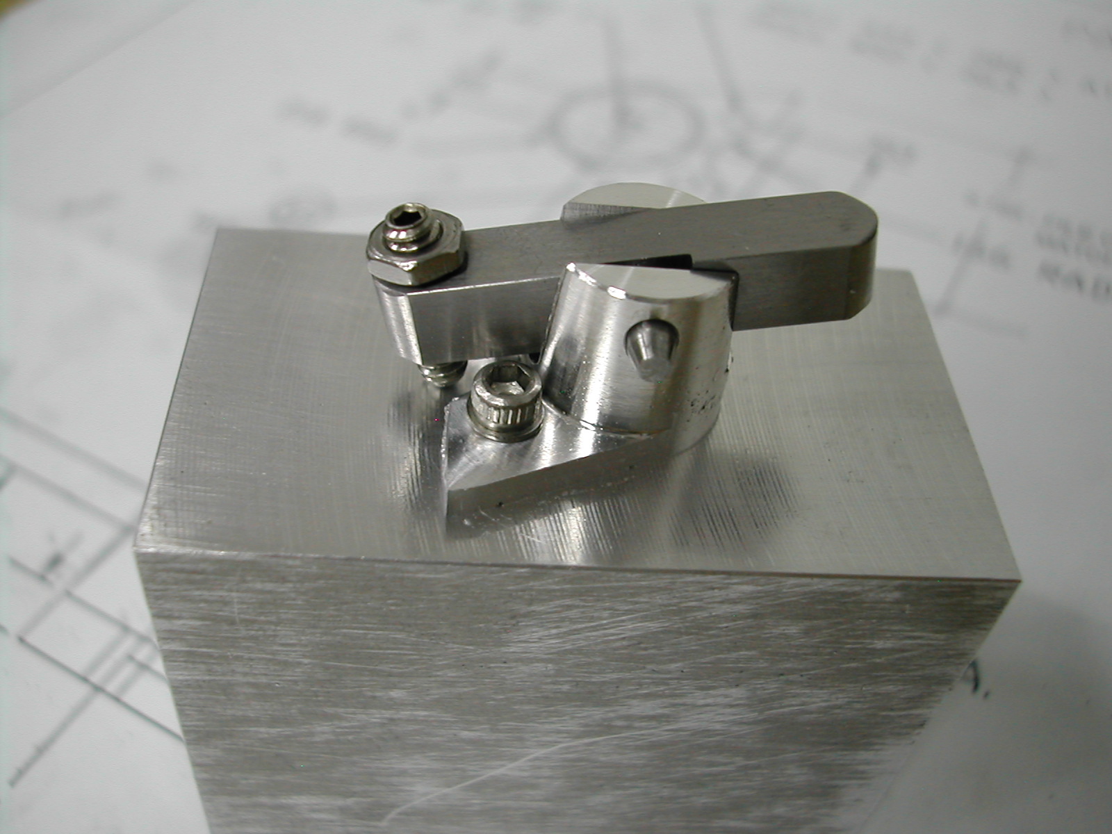
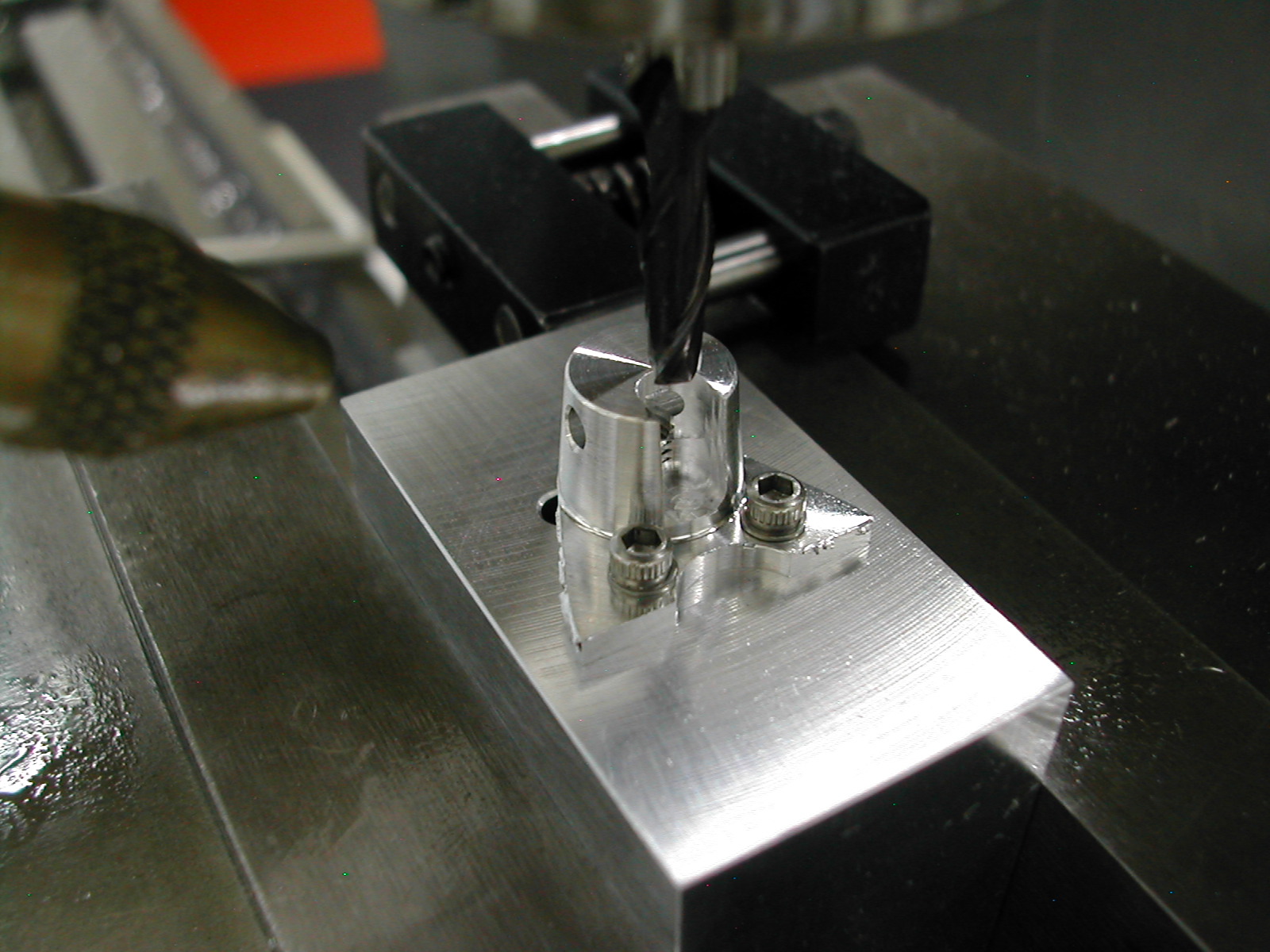 I mentioned that the bottom of the milling fixture had tapped holes instead of pins. Here it is being used to mill the slot for the rocker arms. I felt the additional rigidity resulting from three screws total would be safer and result in less chatter in the slot.
To mill the slot, I used a 4mm end mill with a 1mm corner radius. I pecked across the boss on-center using the quill and the with the quill clamped at the bottom, offset to each side and climb-cut to the finished width.
 I suggest that you test fit a rocker arm before removing the base from the fixture. Because of the fixturing tolerances, the rocker arm slot may not be exactly 90° to the pivot pin hole. Most of my bases worked fine with 0.189″ wide slots, but I needed to open a few up to 0.190″ to get the arm to move freely.
What a pain to deburr!
Disclaimer and License
All material, including the CAD drawings, relating to the construction of the Hodgson Radial presented on this site is free to use any way you see fit. However, no guarantees are made regarding the accuracy or correctness of the material presented here.
Links Used On This Page
(CAD drawings are in AutoCAD 2010 Format)