
 This is a write-up that I did for a local Miata club website back around ’99 or 2000. It includs the schematics but only a few photos, I didn’t take nearly as many back then as I’ve done for more recent projects. And, although the voice here is written as a set of instructions it has been a long time since I wrote this so use anything entirely at your own risk! Here’s the original write-up:
’99 Duetto Seat Heater Installation
Ever since the purchase of the SO’s vehicle, a Nissan Pathfinder LE with its wonderful heated seats, I’ve been adamant that my next car purchase would pamper MY rear. When I finally ordered my new ’99 Miata, you can guess my dismay when I discovered that the Leather Package did not include heated seats. My wonderful wife must have noticed my depression because she surprised me with seat heaters from Duetto Motors, LLC (a Miata.Net supporting vendor) for Christmas! If I hadn’t been jealous, I wouldn’t have been depressed, and my Miata wouldn’t have seat heaters, which by the way are wonderful.
Dealing with Duetto has been a pleasure. No hassles, reasonable prices, and timely delivery. No complaints. I installed heaters in both the driver’s and passenger seats, although you can do just one.
Installing seat heaters is not a hard task, but it can be kind of intimidating when you have to tear into your seats. No special tools beyond the normal Handyman compliment were required and about $10 worth of additional materials beyond what is provided in the heater kits are needed. It took me a full day to install heaters in both seats.
Tools and Materials Needed
- 14mm Socket and Socket Wrench
- 12mm Socket
- 8mm Socket
- 10mm Wrench
- #2 Phillips Screwdriver
- 1/4″ wide Flatblade Screwdriver
- Wire Cutters
- Needle Nose Pliers
- Drill with 1/8″ bit
- Soldering gun and solder
- X-Acto Knife or Razor Blade
- Masking Tape
- Black tape
- Ruler
- Coat Hanger or Stiff Wire
- Optional: Multimeter to check the resistance of the seat heaters.
- About 80 3/16″ x 6″ wire ties. If you have cloth seats you will probably want black ties.
- 6ea ¼” female spade connectors for 16-18ga wire
- 1ea #10 ring terminals for 10-14ga wire
- Female 6 position Molex Connector Radio Shack PN 274-236 $1.39
- Male 6 position Molex Connector Radio Shack PN 274-226 $1.39
- #10 x ½” Sheet Metal Screw
Additional Items Needed for Cars WITH Power Windows
- Relay, NAPA PN 192D $7.88
- 15′ of 16ga hookup wire (preferably, red)
- 1ea ¼” ring terminals for 10-14ga wire
- 2ea 16-18ga butt connectors
- 2ea ¼” female spade connectors for 16-18ga wire
- 2ea ¼” female spade connectors for 10-14ga wire
Additional Items Needed for Installing Two Seat Heaters in a Car WITHOUT Power Windows
- 1ea 15Amp ATO style fuse
Heating Pad Installation
Divide and conquer. That’s the technique we are going to use to keep this task manageable and build confidence in working on our car. Nothing that follows requires an advanced degree in Astrophysics; just follow the steps and you’ll be done in no time. Before we start though, open the seat heater boxes and check that all of the parts are there. If you have a multimeter, you should also check the resistance of the heating elements to make sure they were not damaged in shipping. With both pads plugged together, measure the resistance between the yellow and black wires. It should be between 2.5 and 4 omega.
Seat Removal
First, let’s get the seats out of the car. That way we can take them inside and work where it is comfortable. It will also provide more room inside the car to handle the wiring portion of our task later.
Start by putting the top down (you shouldn’t have it up, anyway). You will need a 14mm socket. I used a ½” drive socket with a 12″ extension. Move the seat all of the way back and remove the two bolts at the end of the seat tracks. Mazda hires gorillas to tighten the seat bolts so make sure the socket is well seated and pull the ratchet toward you. Don’t push it away from you because when it breaks loose, you’ll go flying and probably bust something. If you still can’t budge them, try a few sharp whacks on each bolt with a punch and hammer to break the thread-locker bond. Once the front bolts are out, move the seat all of the way forward and lean the seatback all of the way forward too. Now remove the two bolts on the back of the tracks.
You will notice on the inboard track on the passenger seat that there is a small metal tab secured with a nut blocking access to the bolt holding the rail to the floor. Go ahead and remove this to get access to the bolt. This tab limits the reward seat travel. Before the ’99, the ECU (the computer that controls the engine) was located behind the passenger seat and this kept the passenger from crushing it when he went to stretch his legs. You can leave it off when you re-install the seat if you want to. The only downside to doing this is the seat can now go all of the way back so you loose the little bit of storage you used to have back there. If you do leave the tab off, don’t put you sunglasses back there!
Now just lift the seat straight up and out. Set this one aside while you remove the other. Now let’s move on.
Seat Disassembly
Move one of the seats inside where you have some room to work on it. I found the carpeted living room floor to be the perfect place. Lots of room, and the carpet was gentle on the leather seats. By the way, if you have the standard cloth seats there should be no difference in this procedure. The frames are the same, just the covers are different.
Remove Hinge Bolt
Start the disassembly by removing the small hinge bolt on the side opposite the seat belt receptacle. You’ll need a 8mm socket for this. The black plastic washer might or might not come off with the bolt. If it doesn’t, don’t worry, it will come off later.
Remove Recline Adjuster Handle and Cover
Before we remove the recline handle, use it to recline the seat all of the way back. Now remove the little plastic handle from the recline adjuster. I used the Phillips screwdriver to help with this. Grab the handle with one hand and the tip with the other. Place the shaft behind the plastic handle, touching the metal lever. Now pull. Hard! The handle should slip off. Barbs formed into the metal lever hold it on. Once the handle is off use the screwdriver to remove the two screws in on the mechanism cover. Now rotate the pointed end of the cover up. You will need to press down on the seat bolster to rotate the cover until the tabs underneath disengage from the metal stamping. Now lift up on the rounded end enough to clear the spring underneath and slip the cover off over the lever.
Unbolt Recline Adjuster from Seat Bottom
At the bottom of the recliner mechanism are to gold colored bolts with 14mm heads. Remove these two bolts while supporting the seatback. With the bolts out, you can lift the pivot stud out of the other side where we removed the small hinge screw. If the black plastic hinge washer didn’t come out before, you can remove it now.
Seat Back
Now that we have the seat into pieces, let’s tackle the easy half first. The seatback takes about 10 minutes to complete.
Cut Flap Hog Rings
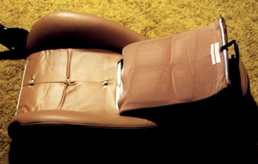
Lay the seatback down with the backside up. At the bottom is a small, loose flap that runs across the seat. Lift this flap up and notice the three copper colored “Hog Rings” that are holding the padded lumbar flap down. Cut these rings with your wire cutters to free the flap. Turn the seat over and flip the flap over to expose its backside.
 Make Wire Exit Hole
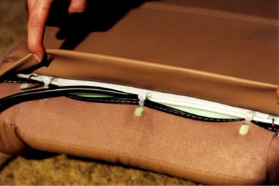
The back of he padded flap is covered with a thin scrim cloth. This scrim cloth is open where the flap attaches to the seat and is sewn at the free end. In the middle along the sewn end, make a small slit in the scrim just below the stitch line with your knife. The slit should be about ¾” long. Just long enough for the plastic connector on the end of the seat heater pad to fit through.
Insert Heater Pad
Everything has been leading up to this, so let’s not wait any longer. Grab the heater without the cutout in the middle and feed the wire and connector under the scrim cloth and out through the slit we just made. Slide the heater under the scrim making sure the adhesive side is facing the scrim cloth. Don’t remove the paper liner just yet. Position the edge 4 to 5″ down from the stitch line. Smooth it out so there are no bumps or bulges paying careful attention to the sides. Now, reach under the scrim and slowly pull down one of the far corners of the paper liner. Smooth the scrim cloth down on the adhesive as you go.
Re-attach Flap
Flip the flap back over into it’s normal position. Turn the seat over, and reattach the loose end using wire ties to replace the hog rings. It is easiest if you start all of the ties before pulling them tight, and the finished ties “set” better if you run the tail of the wire tie though the seat then the flap (the opposite of way from the picture). This causes the head of the tie to end up closer to the seat when the tie is tightened. Position the wire from the heater pad so that the center wire tie will tighten around it to provide strain relief. Tighten the center one first, and then tighten the outside ones. Cut the tails on the ties with your wire cutters. This finishes the seatback. Set it aside and prepare to start on the seat bottom.
Seat Bottom
The seat bottom is a little more intimidating and slightly more complex than the back. We don’t have an easy flap to work with here. We will have to take the cover off of the seat cushion in order to position the heater element. So let’s get started. It will probably take you about 1½ hours to do this the first time.
Remove Seatback Trim
The post that the seatback hinge pin went into is covered with a slip-on plastic trim piece. Remove this and set it aside.
Remove Non-Seatbelt Track
Now we are going to remove the seat tracks. We will start with the one without the seat belt attachment. This is because we want to leave the seat position lever working because it will help with the track removal. Use the seat position lever to disengage the latch pins and slide the seat rail all of the way forward to expose the 12mm headed bolt on the back of the track. Remove this bolt. Now slide the rail all of the way to the back and remove the 12mm headed bolt from the front of the track. Finally, disengage the wire that is attached to the position lever. The easiest end of the wire to disconnect is the one attached to the adjustment lever. Slide the hog ring down to the right angle bend on the end of the wire. Press the tip of the wire down through the hog ring to free it and then work the wire out through the hole in the adjusting lever.
Remove Seatbelt Track
Now we can remove the seat track with the position adjustment lever. Remove the two 12mm headed bolts in the side of the seat though the seat belt attachment bracket. The bracket will not come off because it is welded to the track. Flip the seat back over and move the mounting rail forward and back to remove the two mounting bolts in this track and set it aside.
Remove External Hog Rings
There are approximately 16 hog rings attaching the seat cover to the sheet metal seat pan. Cut all of these with your wire cutters and remove all of the pieces of the rings. Carefully note how the cover is attached at each point, especially at the corners. Note which piece of the cover is on top of the other where the pieces come together at the corners.
Now carefully turn the cover inside out and work the corners off of the cushion. Carefully slip the cover off over the seatback post. At this point you can remove the stamped sheet metal seat pan. It is just set into the foam cushion. Careful, it’s sharp!
Remove Inner Hog Rings
Sorry, the cover is not off yet. We still have another 18 hog rings to go. Pull on of the foam side bolsters down while gently pulling the cover up and you will see another 6 hog rings down in the crevice holding a plastic rail on the cover to the cushion. Cut these hog rings and the six on the other side too. Now lift the back edge of the cover and note a similar arrangement of rings and rail way down in the canyon. There are three rings down there which need to be clipped.
You can get by without cutting the rings holding the front stitch line to the seat if you have a helper which can hold the cover forward so that you can attach the heating pad to the cushion. I found it easier to go ahead and remove the cover entirely.
Make sure you remove all pieces of the wire hog rings from the cover and seat cushion.
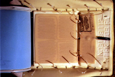
Attach Heater Pad
Large Section and Narrow Strips
The seat bottom heating pad has three sections: The large rectangular area above the cutout; the thin strips on the sides of the cutout; and the smaller rectangular section at the bottom of the cutout. The lower section also contains the thermostat.
Remove the liner paper from the adhesive on the large section and the two narrow strips. Stick the heating pad down on the cushion centered side to side and with the top edge of the cutout just starting down the edge of the stitch canyon in the cushion. Press the narrow strips down firmly to the sides of the canyon. If the heater is positioned correctly, the other edge of the cutout will fall in the corresponding place on the opposite side of the canyon. Get it right the first time because you will destroy the heater if you try and pull it back up.
 Small Section
Before we stick the small section of the heating pad down, we need to remove a small amount of cushion foam to provide clearance for the thermostat and wire so we don’t end up with bulges in the seat cover. Note where the thermostat and wires touch the cushion. Lift the heater up and use your knife to cut a small square in the cushion where the thermostat hits. Make your cuts about ¼” deep and then just pinch the square piece of cushion and rip it out.
Cut out a strip of cushion along where the wire runs using this same procedure. Stop the wire groove at the point where the cushion is the thinnest near the edge. This thin area is formed by the groove where the seat pan nestles in the cushion on the bottom. Make a ¾” long slit through the cushion at the end of the wire groove through the cushion into the seat pan groove on the backside.
Feed the wire and connector through the slit. Remove the liner paper from the last section of heater pad and stick it down to the seat. If you want, you can use a short piece of duct tape to hold the wire down into the groove in the cushion.
Internal Seat Cover Reattachment
The next step is to reattach the cover to the cushion. Notice in the foam cushion where the hog rings were attached the little circular cutouts with a wire running though them. These are the places where we will use wire ties to reattach the seat. Don’t worry, there is enough padding on the seat that you will not notice the heads of the wire ties.
Begin by starting a wire tie in each of the places where a hog ring was. There should be 3 places in each stitch canyon and 6 along each side. You might have to use the slit locations in the back stitch canyon if the heater pad covers the circular areas. It helps to get the wire tie under the seat wire if you use the needle nose pliers to curl the tip before slipping it under the wire. Grab the tip on the other side of the wire with the needle nose pliers and pull the tie halfway through.
Start the 3 ties in the stitch canyon (or 6 total in both canyons if you took the cover completely off) through the plastic rail on the seat cover. If you had to move the ties over because of the heater pad, make sure that you use the corresponding hole in the cover. Now tighten the ties in the canyons starting with the center tie and working your way out. Clip the tails off of the ties. If your wire cutters are too big to get way down there to cut the tails off, you might try a large pair of toenail clippers.
Now reattach both side rails using the same method of starting all ties first then tightening them from the center out.
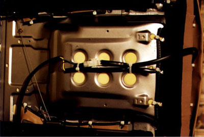
External Seat Cover Reattachment
Slip the sheet metal pan back onto the cushion making sure it goes all of the way down into the groove in the cushion all of the way around. Make sure there are no sharp edges on the pan around where the heater wire touches it on the back edge. Fold the edges of the cover back over the cushion and around the pan. Be especially careful that you don’t cut the cover while slipping the seatback post through it.
Reattach the seat cover to the pan using wire ties. Be sure to grab the heater wires with the back center wire tie to provide strain relief. It works best if you attach the two sides first, then the front, back, and finally the corners.
Re-assembly
Re-assembly is the opposite of the disassembly with a few added steps to handle the new wires. I suggest using a thread-locking compound on all of the fasteners as you reinstall them.
Attach Seatbelt Track
Begin by attaching the seat track with the seat belt attachment. Start the two bolts in the track, but don’t tighten them completely. Start the two bolts in the seat belt bracket then tighten them securely (14-19 ft-lbs). Then tighten the seat track bolts to 14-19 ft-lbs.
Attach non-Seatbelt Track
Re attach the adjuster wire first, start the front track bolt, then the rear bolt. Then tighten both bolts.
Attach Recline Adjuster
Slip the seatback post trim over the post. Now position the seatback in place. Make sure the seatback pivot pin is in the hole in the seatback post. Install the two 14mm headed bolts through the recline adjuster into the seat bottom. Tighten them to 27-39 ft-lbs.
Replace Recline Adjuster Cover and Handle
Replacement of the adjuster cover and handle are just the opposite of removal. No adhesive is needed when replacing the handle as the barbs on the lever will grip it securely.
Replace Hinge Bolt
Turn the seat over to the other side and manipulate the seatback until the pivot post is centered in the opening. Press the plastic washer back into place, and reinstall the hinge screw.
Secure Heater Wires
The next step is to secure the heater wires to the heater pan. We need to make sure there is enough slack so the wires are not strained when the seatback is moved. To accomplish this, adjust the seatback all of the way forward. Now use a wire tie to secure both cables to the seat pan. There are 6 large holes in the pan; use the back two for this first tie. Now connect the two cables together and use a wire tie though another pair of holes to secure the cables in front of this connection to the seat pan. This will prevent the bottom and back heater from becoming accidentally disconnected. If this happens, neither heater will operate.
Testing
If you have a multimeter, recheck the resistance of the heaters now that they are installed. You should have the same reading as before. Now go install the heaters in the other seat.
 Switch Installation
Up until this point, the installation has paralleled the heater manufacturer’s instructions. This is where the differences begin. Included with the seat heaters is a stamped black sheetmetal bracket for each heater switch. Perfectionist that I am, I opted for a more OEM look and installed the switches in the center console.
Removing Center Console
Begin by removing the center console. There are 5 Phillips head screws and two clips holding the console in the car. There is also a wire harness clip that needs to be disconnected from the console.
Screws
Remove the two screws located in the locking compartment. Remove another screw located under the ashtray. Just pull the ashtray straight up to access this screw. Finally there are two screws located under little round covers; one on each side at the front of the console. Use a flatblade screwdriver in the little slot around the edge. Use the widest screwdriver you can to keep from deforming the plastic cover. Carefully pull until the cover pops up. Don’t pull it all of the way off! It’s supposed to be attached. Now remove both screws.
Finally, back in the ashtray opening, there is a black barb to the left of where the screw was. This is the backside of a wire harness tiedown. Squeeze the two ears of the barb with your needle nose pliers and push it down to disengage it.
Shifter Knob
Unscrew the shifter knob counterclockwise. If you have the stock knob, just turn hard. There is nothing else holding it. If you have an aftemarket knob you’re on your own.
Front Clips
Finally there are two mysterious, magical clips holding the front of the console to the center radio trim. I thought I was going to break something the first time I popped these loose, but I didn’t. It takes a lot of force to separate them. Do one side at a time. Get your fingers under the edge of the console, and use your thumb against the center trim on top for leverage. You don’t want to just get your fingers under the console and pull, because when it pops loose you’ll keep on going and then you WILL break something.
After both clips are popped loose, lift the front end of the console straight up about 6″. If you have power windows, you will need to reach underneath and disconnect the wiring connector from the PW switch. There is a little catch you need to press to release the connector.
Continue lifting the front end and begin sliding the console forward. The trunk release and gas cap levers will slip out thought the rubber trim. Once the handles are clear, you can lift the console out of the car.
Measuring, Marking, and Cutting
Up to this point, all of the changes we have made have been hidden. Here is where we make the first visible modifications to our car. Be really careful during these switch-mounting steps; I don’t think you want to buy a replacement center console. There is very little room for error when placing the switches. Measure TWICE, cut ONCE. Don’t blame me if you mess this up. Mine turned out perfectly. Yours can too if you work carefully and slowly.
(If you don’t have power windows, you could put the switches where the window controls go and save yourself a little trouble.)
Locate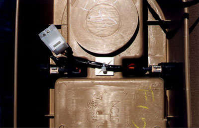
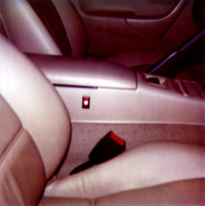
Turn the console over and examine the compartment area. There is a small space on each side between the circular “Cup Holder” area and the rectangular storage area. This is where we are going to mount our switches. Neither my wife nor I finds this location to be inconvenient. I guess it is possible that a person of large proportions might not be able to reach the switches of might inadvertently flip the switch. One benefit of putting the switches here is that they can be rather bright when turned on. At night, this location causes no distraction whatsoever.
I placed a few strips of masking tape on the outside to aid in locating the switch cutout. The switches supplied with my heaters needed a 9/16″ x 1-1/8″ cutout. Check yours before proceeding and adjust accordingly. I drew the location of the cutout on the tape in pencil making sure the switch was square with the top edge of the covered compartment. Both the bottom edge and the compartment top are curved so don’t try to use these to align the switches.
Note that the cavities for the drink holder and the storage areas do not have straight sides. This is known as “Draft” and allows the console to be pulled out of the mold during manufacture. When looking at the underside of the console, this makes our switch gap larger at the top that it is deep down inside. Be sure to take this into account too. Try and position the switches as far down (closer to the lid when the console is installed) as possible. Be careful of the boss sticking up on the hinge side.
Scribe
Once I had the cutouts marked on the tape and I had measure and checked for the 100th time, I was ready to commit. I used a very sharp knife (a large X-Acto) and a metal straight edge to scribe the lines into the plastic console. Be careful and don’t scribe beyond the corners of the cutout.
Drill
I removed the tape and used a drill and 1/8″ bit to drill a series of holes around the inside edge of the waste area. It is easier to drill the holes next to each other instead of trying to overlap them. It is easy to cut the remaining material between the holes.
Cut
Cut the majority of the waste piece out with the knife. I then used the knife to slowly pare the opening to the scribed line. Check the size of the hole with the ruler and test fit the switch often. Be careful not to push the switch all of the way in until you are really done. It is a bear to get back out. Once both holes (if you are doing both seats) are finished and the console is cleaned up, snap the switches into place. Be sure to orient the switch with the little seat picture down when the console is installed. Switches are normally installed so that the off position is down and on is up. The seat picture corresponds to the off position.
Wiring
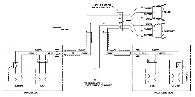
The wiring of the seats is another change I made. The harness provided by the manufacturer requires the supply power to be run out to the seats and then brought back to the switches. This would make two cables under the carpet for each seat. The flag style spade connectors on the switch end of the cables would not fit in the narrow place where I positioned my switches. And I thought a connector between the switches and the harness would be handier if I ever needed to remove the console again. The alternative would be to disconnect 6 spade connectors from the switches up in the tight little space.
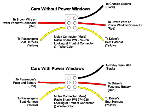
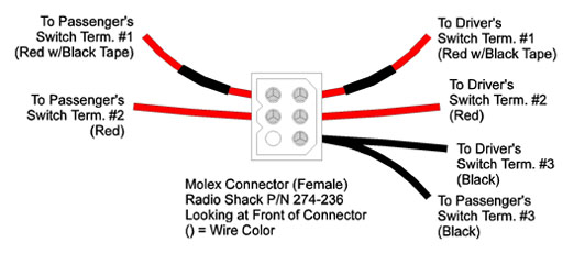 The first thing to do is to make a little wiring harness for our console. Start with four 6″ long pieces of red wire, and two 6″ pieces of black wire. You can cut these from the ends of the power harness provided with the heaters. Put a small piece of black tape on two of the red wires. Now crimp and/or solder a ¼” female spade connector onto one end of each of the wires. On the other end, crimp and/or solder one of the contacts from the female Molex connector (Radio Shack P/N 274-236). Attach both black wires to the same contact (you will end up with one Molex contact left over). Push the contacts into the connector shell from the back until they click.
Now attach the spade connectors to the switches following the same diagram. A pair of needle nose pliers helps to seat the connectors.
Seat Harnesses
Now we do a little modification to the seat harnesses. Clip the 3 flag spade connectors from the end of the red, yellow, and black wires on each harness. On the other end of the harness there are two connectors. One has a yellow wire and two black ones, the other has a red and black wire. Determine which black wire in the connector with containing the yellow wire connects with the other plug. Cut this wire about 1″ above the connector with the yellow wire. You can now remove the black sleeving over each harness and separate the two connectors. Tape the cut black wire to the other black wire. Be sure the end of the cut wire is covered. Reinstall the longest piece of sleeving back over the yellow and black wires. You can use some black tape to anchor the sleeving close to the connector. Set the connector with the red and black wires aside; we won’t be needing it.
Use a coat hanger or other stiff wire to fish the loose end of the wire under the carpet in the car. You want the connector to hang out of the little cutout in the carpet under the seat, and the loose end to come out in the hole in the carpet around the shifter. Secure the connector end so there is 2″ to 3″ of cable extending from the cutout.
Power Wiring
We need to bring power to the console area to operate the seat heaters. Since we don’t want the heaters to draw down our battery when we aren’t there to enjoy them, we want to use a switched power source. The Miata has two kinds of switched sources; those that work when the key is in the accessory position (IG1) and those that only work when the key is in the run position (IG2). I chose to allow my seats to only run while the engine was on. That way I couldn’t inadvertently run down my battery if I was listening to the radio and forgot to shut off the seat heaters. The heater manufacturer provides a means to tap into an existing power source at the fuse box to obtain power for the seats. In my opinion, the Miata designers in their quest to save weight designed the wiring in the car to be just big enough to carry the original load. Adding another 8 Amps (or 15 Amps if you are installing 2 heaters) to an existing circuit is just asking for trouble. So to play it safe, I brought power straight from the battery. If you don’t have power windows, there is an easier way. DISCONNECT THE NEGATIVE TERMINAL FROM THE BATTERY BEFORE CONTINUING (requires a 10mm wrench).
Cars with Power Windows
Since there is no convenient, safe source of power for our heaters we will have to bring it from the battery in the trunk. Attach the ¼” ring connector to one end of each of the supplied fuse holders. Use a butt connector or solder and tape the other end of each fuseholder to each end of the hookup wire. Now hold the ring connector and fold the wire exactly in half. Attach the ring connector to the positive battery terminal under the nut. Feed the folded end of the wire out to where the trunk release and gas cover releases come out inside the cockpit. You can install the supplied 7.5A fuses into the fuse holders.
To do a nice neat job, you might have to remove the trunk trim. Remove the carpet and battery cover. Take the screw out in the bottom of the plastic storage bin and remove the bin. Now remove the back and right side trim pieces. The little black fasteners can be removed with only your fingernails. Grasp the center round piece and pull out about 1/8″ then grasp the outside and pop the fastener out. Remove the back piece first and then the right side piece. Reverse to replace. Pop the plastic fasteners into the body and then press the center part back down to reinstall them.
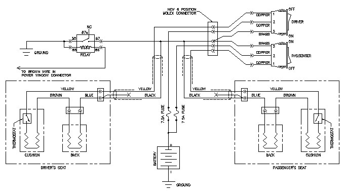
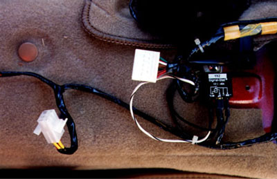
Now that we have power under the console that we can use, we need to make sure our heaters will shut off when the engine is not running. We can accomplish this by adding a relay and controlling it with the power window supply. The relay will not draw any appreciable current so we will not be endangering our power window circuit. There is just enough area between the ashtray and window switches to mount our small relay. Mount the relay using the sheet metal screw so that the edge of the relay is about 1″ behind the existing screw hole and the relay body is centered over the raised portion on the transmission tunnel. You will need to cut the existing little “U” shaped cutout in the carpet down a little further so the relay can mount firmly to the sheetmetal.
 Make a ground wire by connecting three 6″ pieces of black wire to the #10 ring connector (remember where we got the black wire for the switch harness?) Combine two of the other ends into one female spade connector. Attach another spade connector to the remaining wire. Fasten the ring terminal under the mounting screw for the relay. Attach the spade connector with the two wires to terminal #30 on the relay. Attach the remaining spade connector to terminal #85 on the relay.
Attach another ¼” female spade connector to another 6″ piece of wire. If this connector is not insulated, be sure to wrap it with electrical tape. Use a 3M solderless tap connector or solder the other end of this wire to the brown wire going to the power window connector. Connect the spade connector to terminal #86 on the relay.
The final step in the relay install is to connect both black wires coming from the seat harnesses along with a 12″ piece of wire to a ¼” female connector. Connect these wires to terminal #87 on the relay.
Cars without Power Windows
The wiring for cars without power windows is much easier. Mazda has already brought a switched power source out under the console. We only need to energize it. Lets start by connecting our ground. Combine the two black wires coming from the seat harnesses with another 12″ piece of wire and insert into the #10 ring connector. Use the sheetmetal screw to attach the connector to the raised area on the transmission tunnel 1″ behind the hole where the ashtray screw goes.
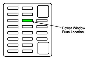 Use solderless taps or a solder connection to attach two 12″ pieces of wire to the brown wire going to the power window connector. If you are installing only one seat heater, replace the current Power Window fuse in the Miata with the 7.5A fuse that came with the kit. If you are heating both seats, you will need to install a 15A fuse in the PW position.
Mating Connector for the Switches
To finish the wiring we need to install the male 6 position male Molex connector that will mate with our switch harness on the console. Position the pins in the plastic shell according to the appropriate drawing below.
Putting it Back Together
Well, this is it. Vacuum out the car, clean off the seats, and give the console a final cleaning before we reinstall them.
Re-installing the Console
Reinstall the console. Slide the console backwards over the trunk and gas levers and reattach the PW connector, push the wire loom back into the hole on the bottom of the ashtray, and connect our new seat heater power plugs before snapping the front of the console down. Make sure all of the wire are tucked up under the console, and reinstall all five screws. Finish by reinstalling the shift knob. Be sure to line up the shift pattern.
Re-installing the Seats
Set the seats in the car and connect the seat heater cable beneath them. Start the four bolts that hold the seat in place and then check that the seat wiring is not being pulled on at any point in the full range of seat motion. If the wires are okay, go ahead and torque the seat bolts to 29-37 ft-lbs.
Testing
Reconnect the negative battery terminal, and turn the key to the RUN position. Turn the seat heater switch to the on position. The switch should light. Turn the key to the ACC position and the seat heater switch light should go out. The light should stay out when the key is turned OFF.
Now go for a little test drive. The seats should heat up in about 5 minutes. Check to see that both the seat bottom and back are being warmed. That wasn’t so bad was it? Happy winter motoring!