
 Once again, the problem of obtaining high quality materials here in China made for a little more work in creating the valves. To obtain the necessary material, I used heat-treated stainless bolts sourced from McMaster-Carr in the US as my base material.
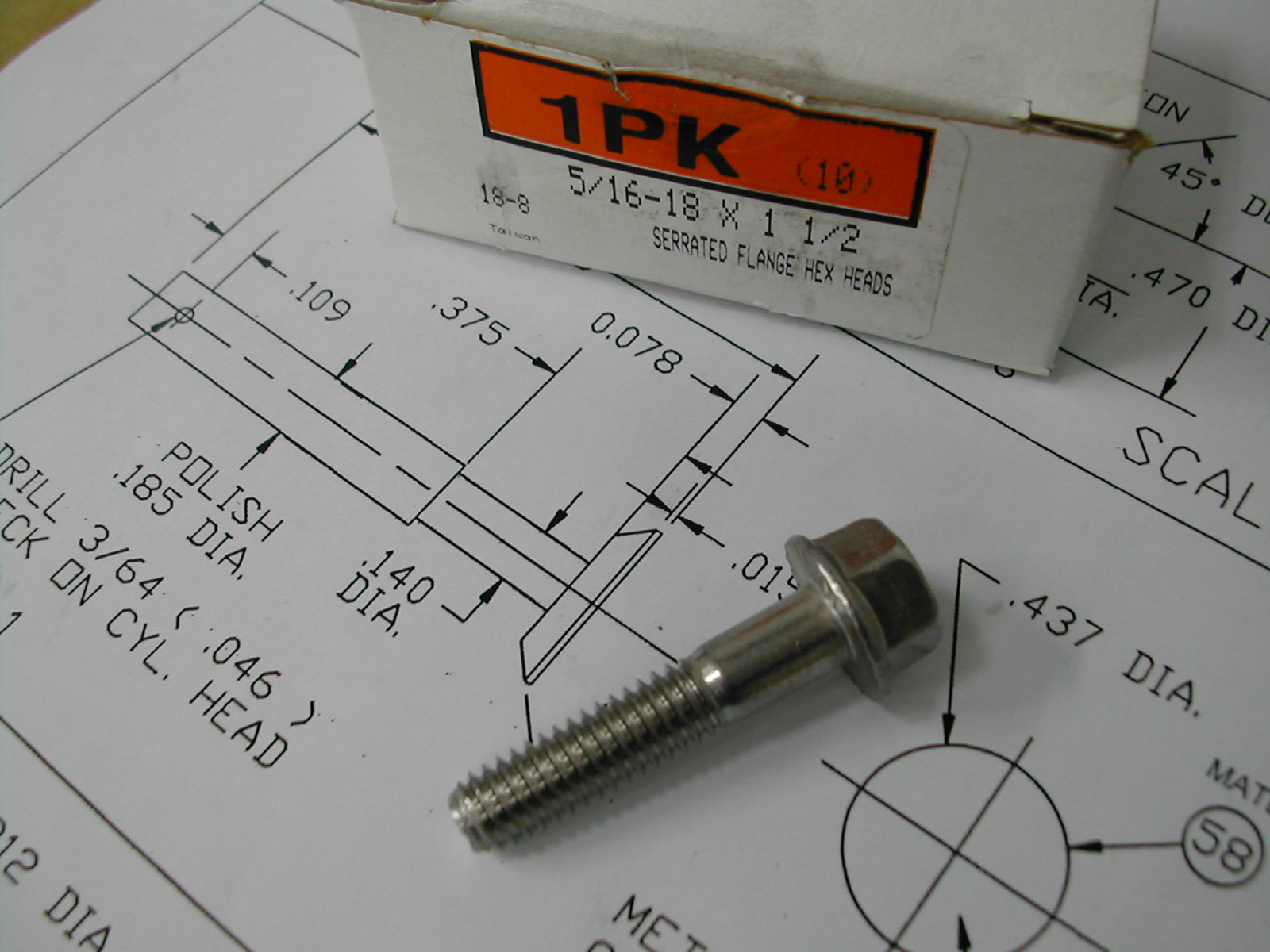 The bolts, p/n 97646A165, were 5/16″x1.5″ 18-8 stainless flange head bolts. These were heat-treated to 100,000 psi and around HRB100 in hardness. I like working with pre-heattreated material – not only is it higher strength, but machining it with carbide tools results in very nice surface finishes.
 I’m turning the bolt heads down to 12mm. This leaves some stock to be removed later when I can chuck on the final shank diameter and insure the valve face is concentric.
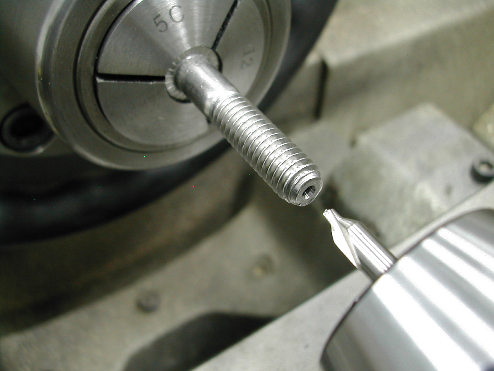 The shank ends need to be supported when turning, so I’m center drilling to use a live center in the tailstock. Make this center as small as possible because it will need to be removed later.
 With the center in place, I’m roughing down the valve shaft to about 0.005″ over the final dimension.
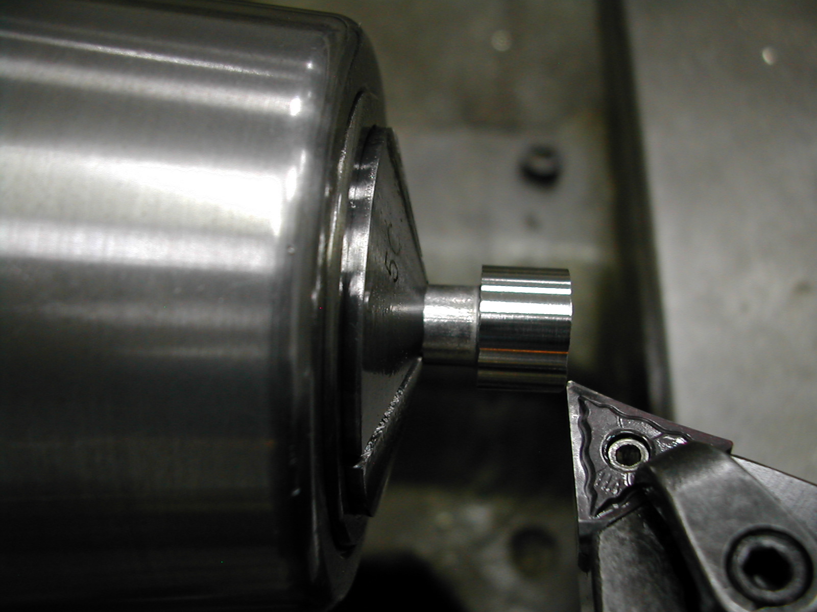
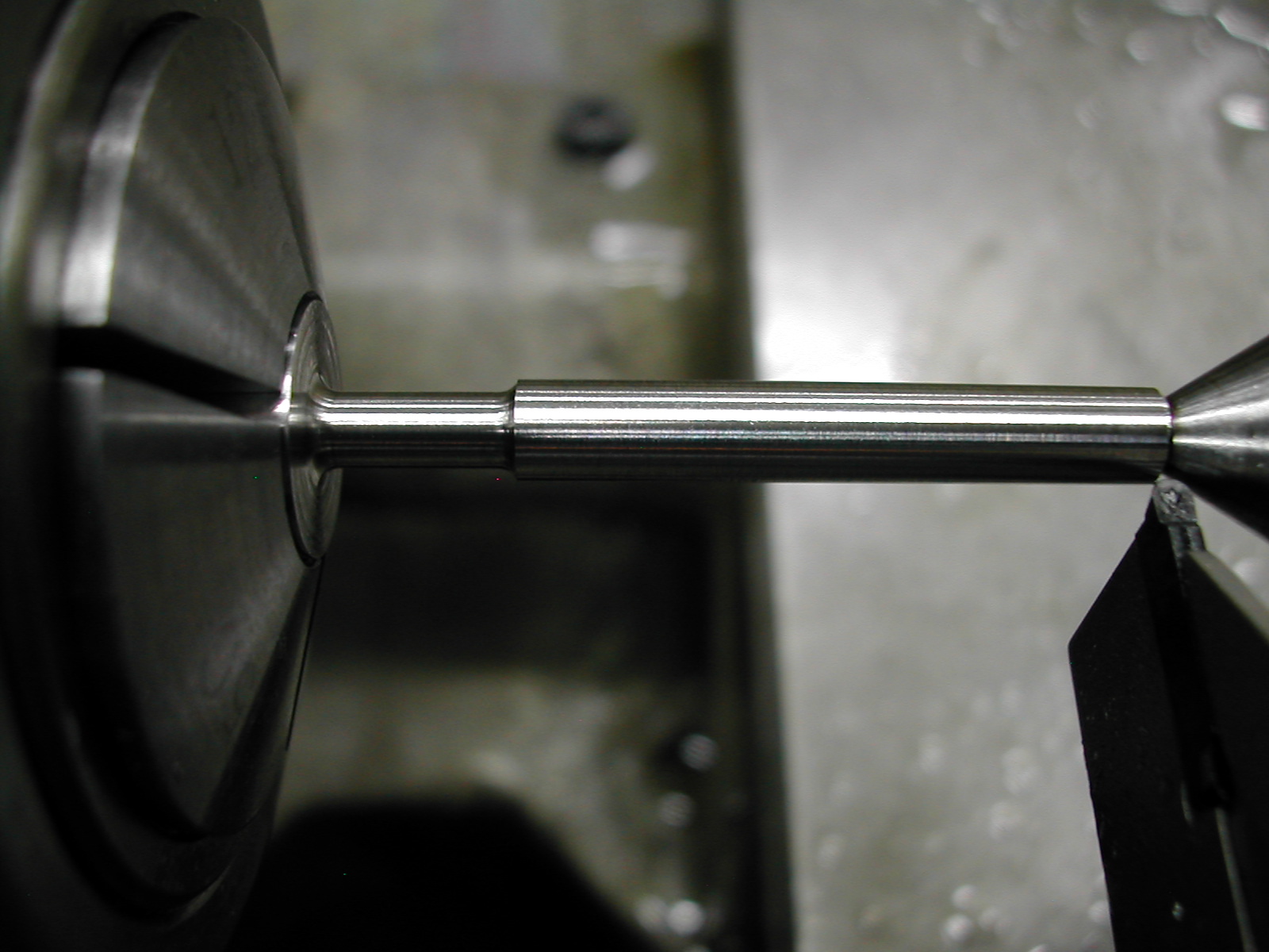 With a 1mm radius insert, I’m profiling the neck area as well as turning the shaft to the finish O.D. At this point, the shaft is still about 1/4″ long – the excess, and the center, will be trimmed off later.
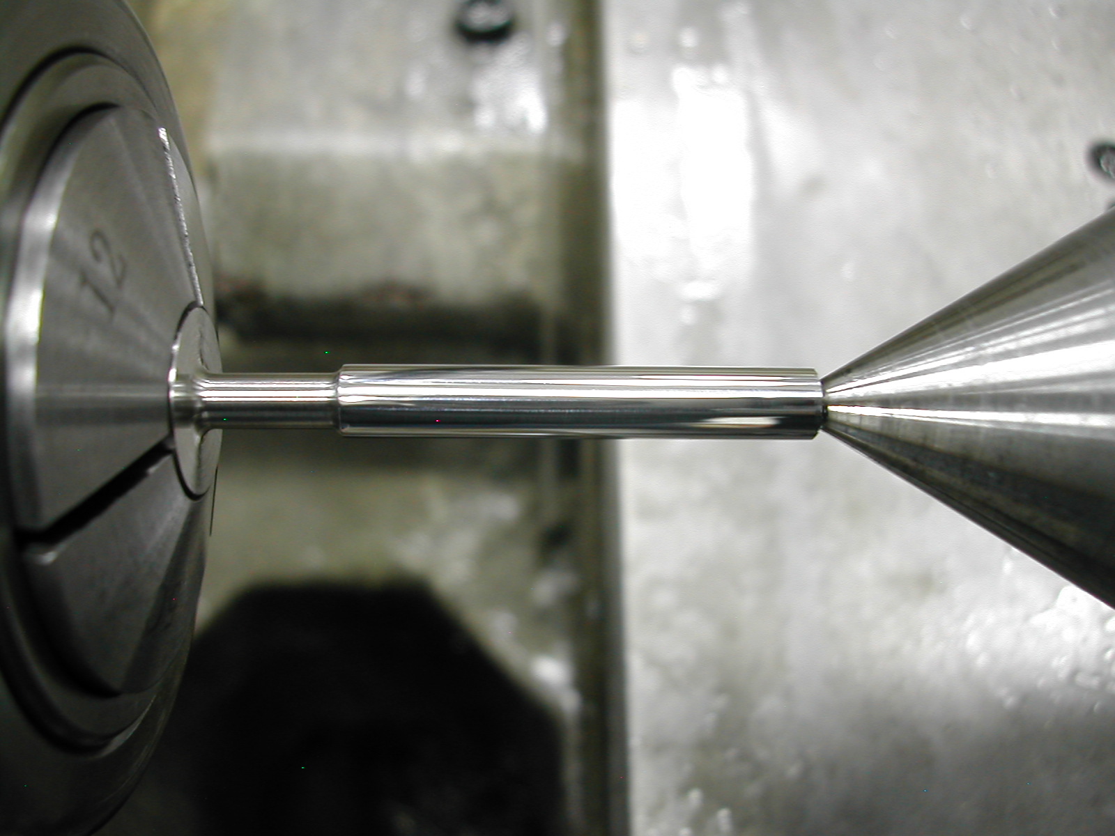 The large radius on the finish tool produces a great surface finish on the hardened material. Still, some wet polishing with 3000 grit and then 5000 grit paper should make these run smoothly.
 There is almost 5/16″ of excess material to remove from the face end of the valve. With the valve neck now at 0.140″, I was concerned about bend or twisting the valve if I tried to remove this amount of material by just clamping on the valve stem. Therefore, I decided to grip the valve by as much of the face as possible.
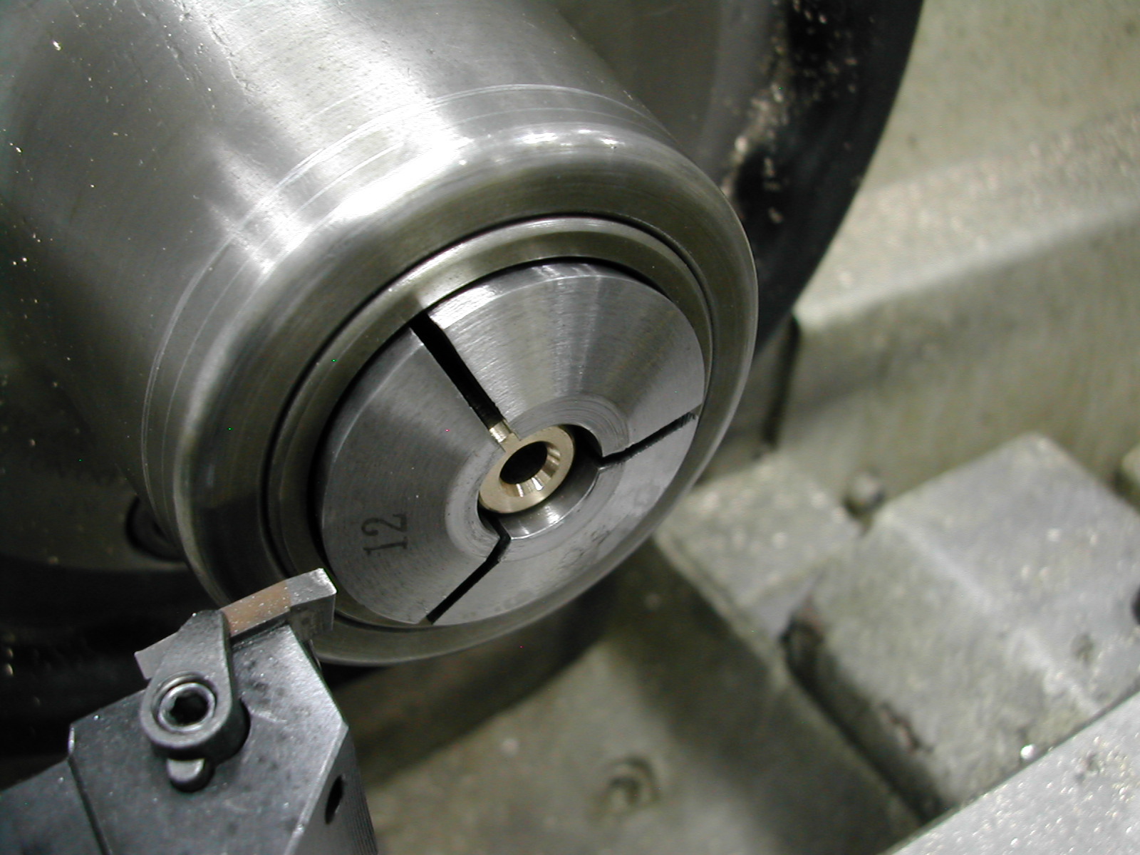
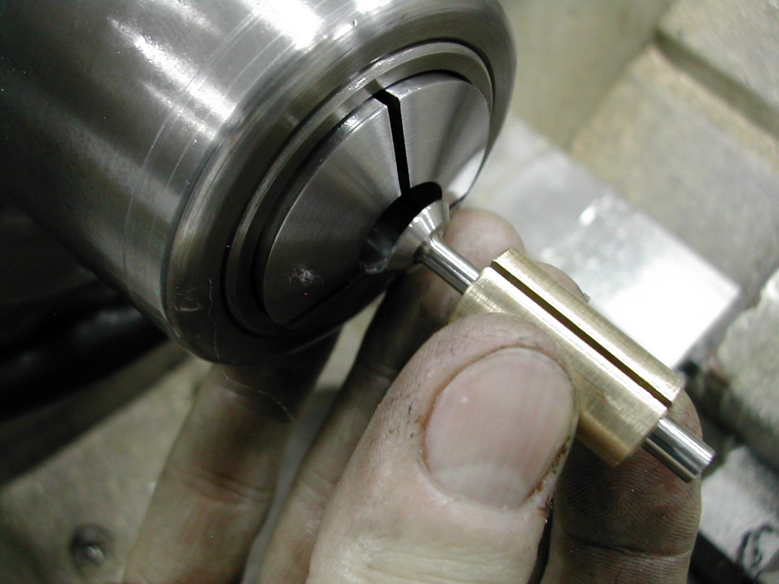
To do this, I pressed on a short piece of brass to my 5C stop rod. The stop was then adjusted to sit 0.080″ shy of the face of the collet. With the 5C collet stop reassembled and attached to my 12mm collet, I then drilled and reamed a 0.1865″ hole in the end of the brass. I did this after the stop was assembled to the collet to insure concentricity.
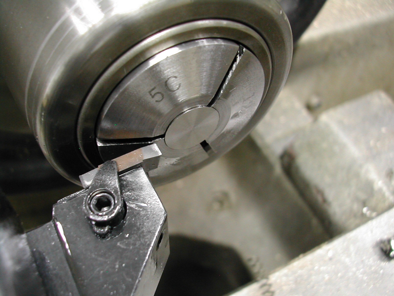 The valves are then faced to about 0.090″ since it’s impossible to measure the thickness exactly with this setup.
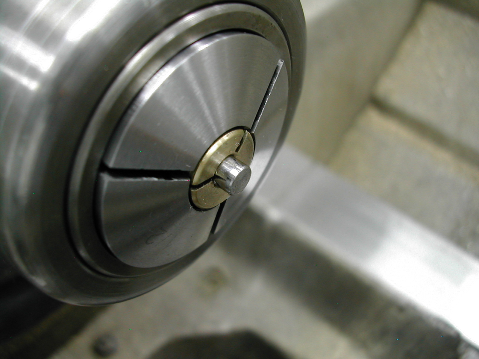
 With just a little bit of the valve extending in front of the collet, removing the part was required using an X-Acto knife in one of the collet slits to get behind the valve and push it out.
 With the excess material removed from the face of the valves the next step was to finish profile the complete top of the valve.
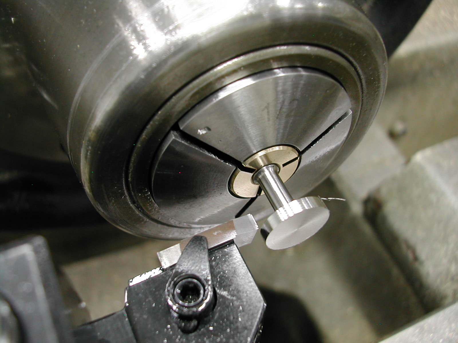
I made split collet out of brass to hold the valves while machining the faces. Again, I could have used a 3/16″ collet, but would risk scratching the polished valve shaft with the hardened collet.
 Step one in finishing the faces involved taking a light skim cut on the face to establish a zero point.
For this whole process, I’ve rotated my tool a few degrees from square so it’s cutting with the 0.4mm corner radius instead of the cutter face.
 The next step was to turn the O.D. from 12mm down to the 0.437″ finished dimension. I first plunged most of the excess off with the face of the tool, and then fed across allowing the back corner to cut the final dimension (remember the tool is rotated a few degrees).
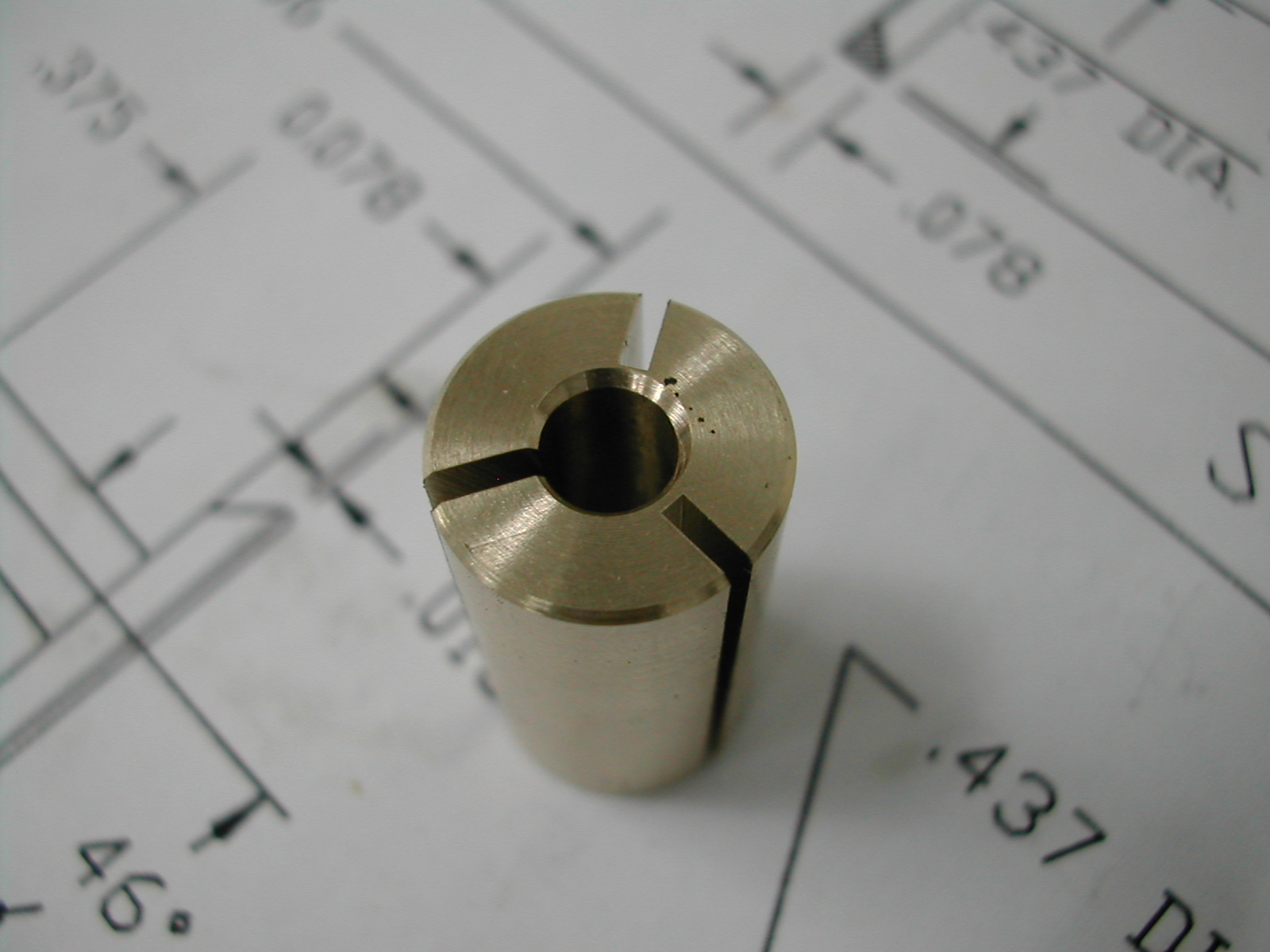
 Finally I generated the 46° angle with the crossslide. These three steps were then repeated for the rest of the valves.
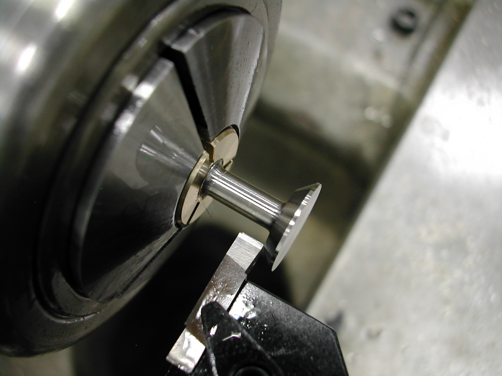
 Next, I installed a collet stop on my 5C collet and turned the valves around in my brass collet to remove the center hole from the shank end and bring the valves to the finished length.
 I probably should have changed tools to one of my smaller part-off inserts, but this profiling insert worked OK for the job once I cocked it a little more.
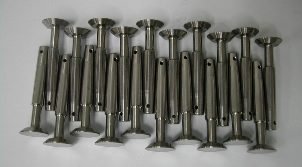
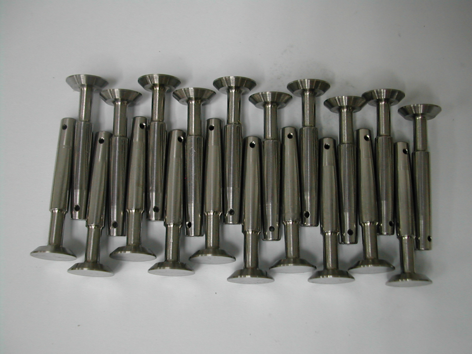
 Here’s the finished end with a small radius added.
 For drilling the 0.046″ retainer pin hole, I made a quick drill jig out of brass. I didn’t have a correctly sized drill bushing, so I made one out of a small piece of 1/8″ hardened dowel pin drilling through with a #56 carbide circuit board drill.
 To drill the holes in the mill, I’ve set up a vise stop and a single parallel along the fixed jaw, and indicated in the hole position. The valve is loaded into the jig, and the jig clamped into the vise. The act of clamping holds not only the jig in the vise, but the valve in the jig. I’ve used a small scrap of paper to keep from marring the face of the valve.
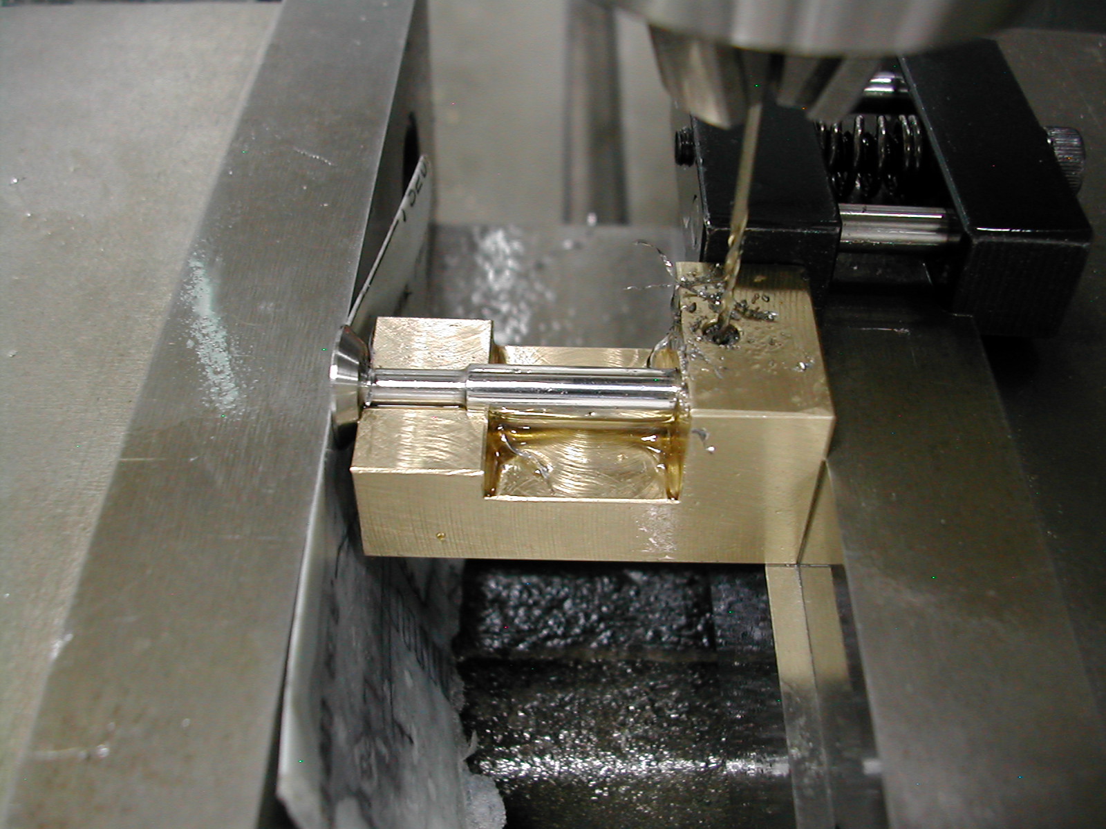 Since these valves were pre-hardened and they also tend to work harden, it was very important to use a high-quality cobalt drill, a firm feed rate, and lots of cutting fluid to make the holes. I don’t suggest carbide here as a drill this size is very brittle and likely to snap when exiting the far side of the valve.
 After drilling the holes, they were deburred and then hit again with some 5000 grit paper to remove any remaining material that might catch in the aluminum valve tower.
The final step will be to lap these valves into the heads.
The plans call for a simple rigid valve stem chuck. I was concerned that this could induce side loads during the lapping process and given that there is 0.002″ of clearance between the stem and the valve towers might cause some sealing problems.
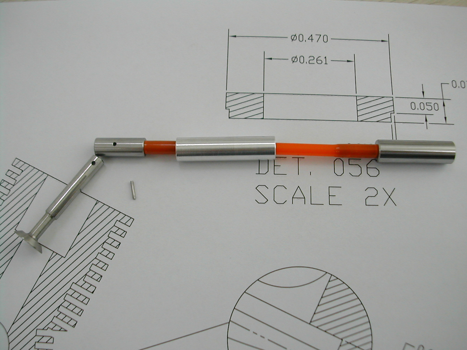 To counter this, I made a lapping chuck with a flexible section. The flexible section was a piece of 6mm O.D. x 1mm wall urethane tubing. This was attached to a 0.250″ O.D. chuck that fit over the valve and was drilled for the valve retainer pin.
Over this was a 5/16″ O.D. aluminum collar that slid down to cover the retention pin. On the other end of the flexible tubing was a 5/16″ rod to fit in the portable drill chuck.
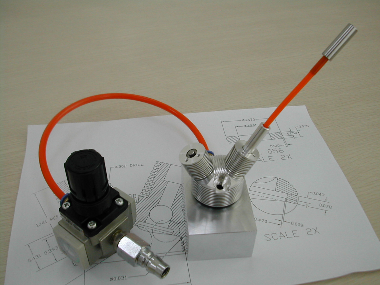
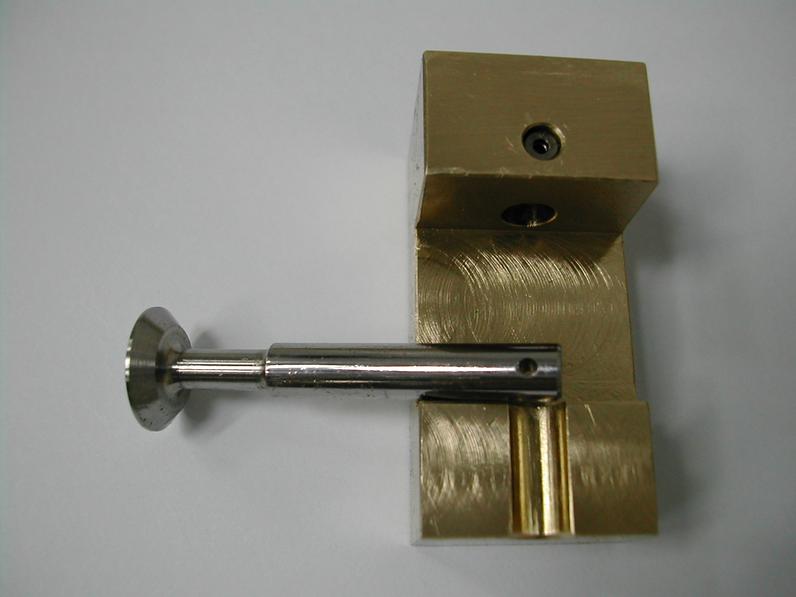
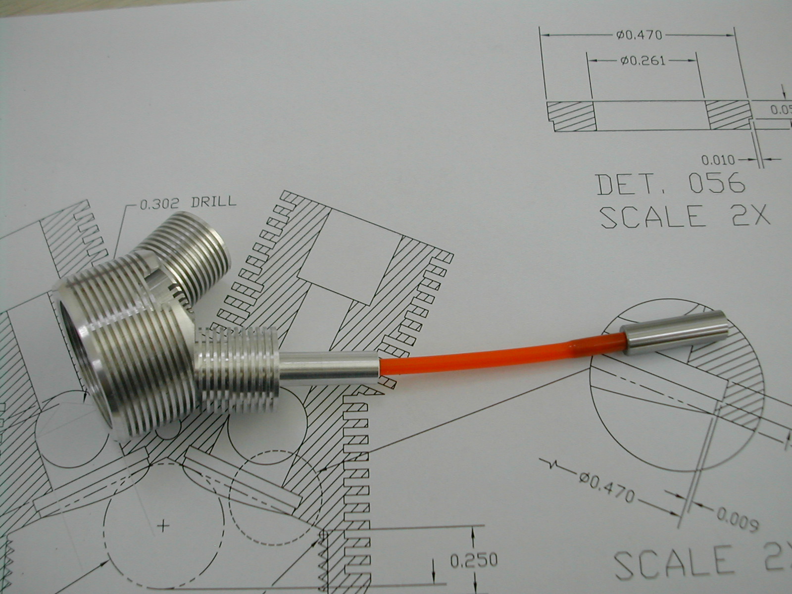 Here is the lapping chuck assembled onto a head.
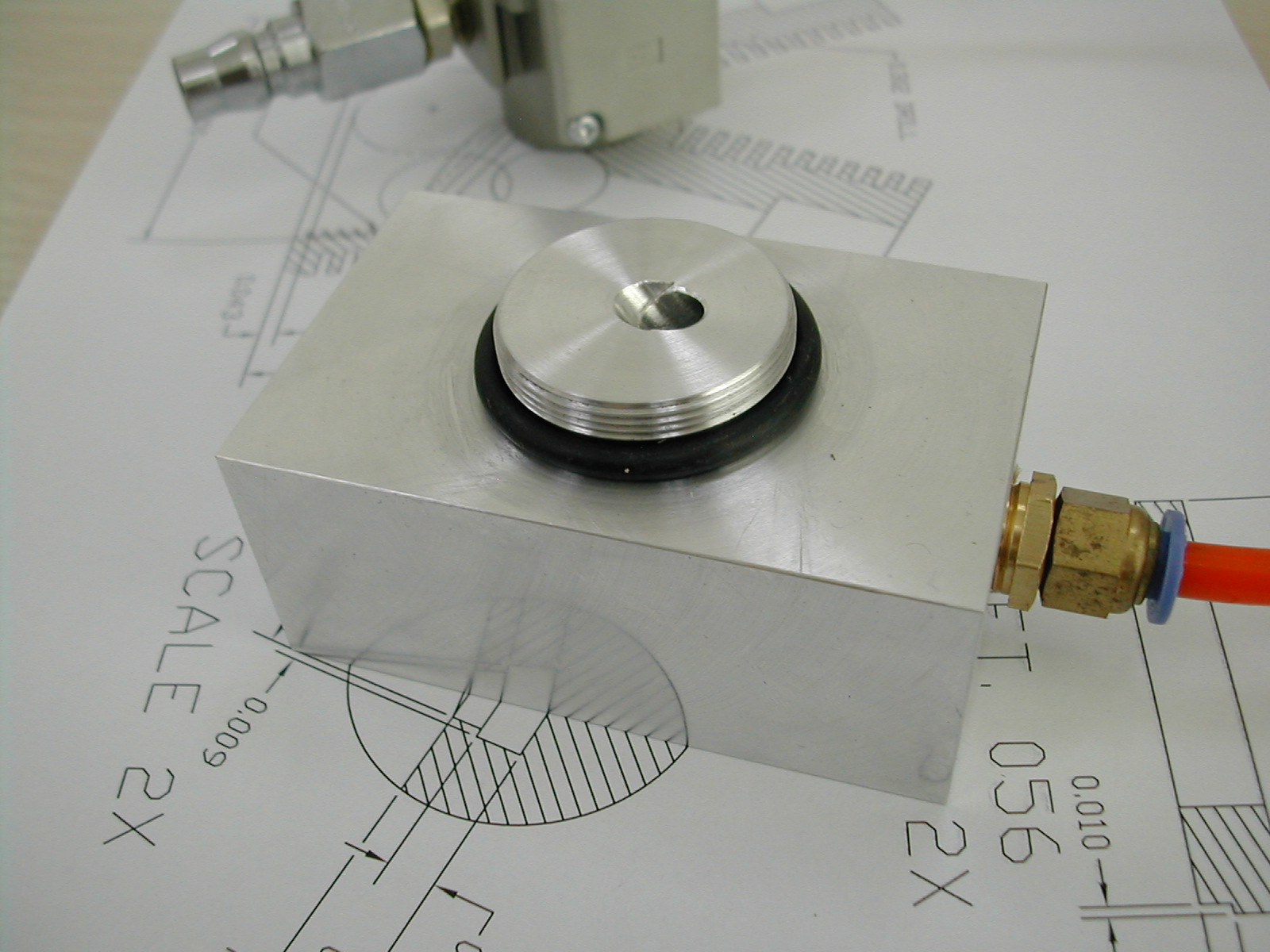 Here is the lapping base I made from a scrap of aluminum. I turned a boss with the 1.250″-24 thread and affixed an AS568-216 O-ring to seal on the heads.
At this point, all I need is a sparkplug and some non-embedding garnet lapping compound. A good source for this compound is your local school band instrument supplier. It is used to lap the valves on the Brass instruments. I ordered mine online from MusicMedic.com
TO DO
- Add some photos here showing the actual lapping process
Disclaimer and License
All material, including the CAD drawings, relating to the construction of the Hodgson Radial presented on this site is free to use any way you see fit. However, no guarantees are made regarding the accuracy or correctness of the material presented here.