
 The Hodgson plans call for the valve seats to be made from Alloy 954 Aluminum Bronze (here in China this is called QAL 9-4 bronze or C63000 nickel aluminum bronze). These valve seats are retained in the head only by a 0.002″ interference press fit. Retention by only a press fit between components subject to heating and cooling cycles between two materials having different coefficients of thermal expansion is a problem waiting to happen in my opinion. I wanted a different method for retaining the valve seats, and I agree with the Hodgson’s that is shouldn’t be an anaerobic retaining compound like Loctite RC680 that is used elsewhere in this build.
I finally settled on swaging the valve seats in place ,and ran a couple of experiments to prove it’s validity. Below are the results of those test and the design I finally settled on. This is followed by the machining of the actual valve seats. The installation of the valve seats is covered in the head build log.
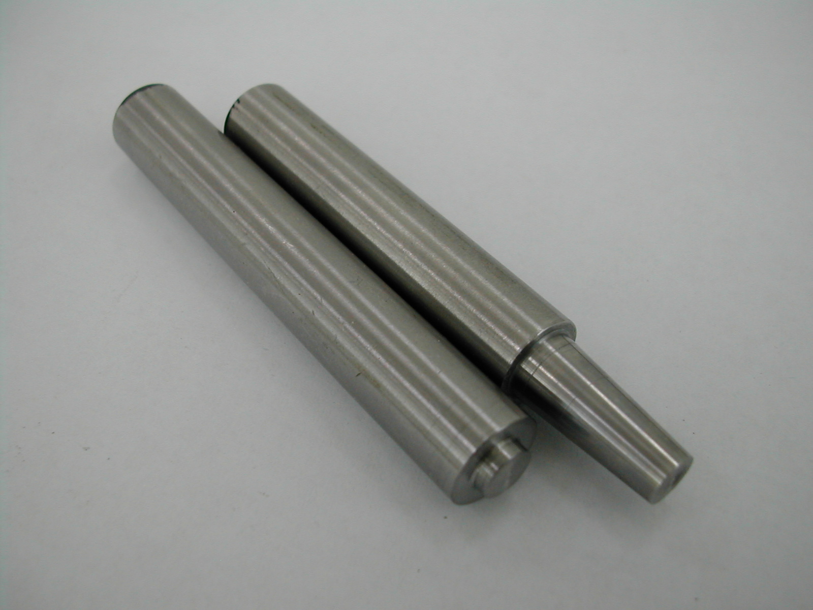 I made a couple of tools to test my swaging idea. I had some 12mmx80mm dowel pins (practically the same size as the valve seat diameter I was planning on making) laying around, so I proceeded to turn a 0.255″x0.078″ boss on one to use as an insertion tool. On the second, I turned a 3.5° per side taper with the small end at 0.260″.
Carbide tools did a pretty good job of cutting these dowel pins, but I went ahead and polished the tapered tool as best as I could afterwards. The first would be used to drive the seat into the head, and the second to expand the seat under the lip I envisioned.
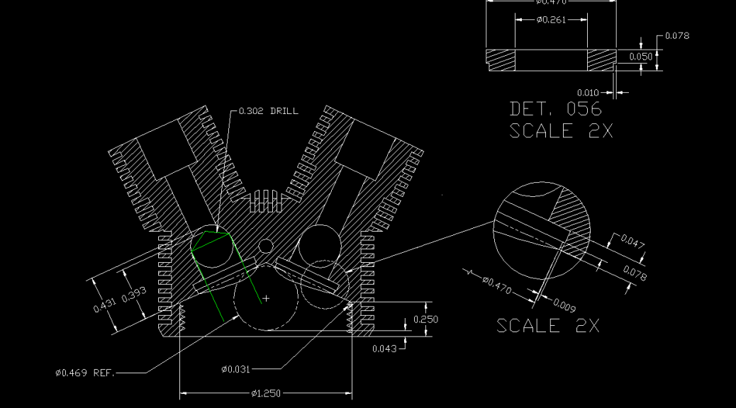
I tossed a piece of scrap aluminum in the lathe, and started by drilling a 0.302″ pilot hole. Next I counterbored this to 0.470″ in diameter by 0.078″ deep, and then added a 0.010″ undercut with my 0.047″ wide tool. I turned a bronze seat to 0.470″ diameter, then reduced this by 0.010″ per side leaving a 0.047″ wide lip. After parting this off to 0.078″ wide, I proceeded to insert and then swage it into my aluminum test piece. Once swaged, I ran a 5/16″ ball-end endmill through it and countersunk it with a 90° countersink.
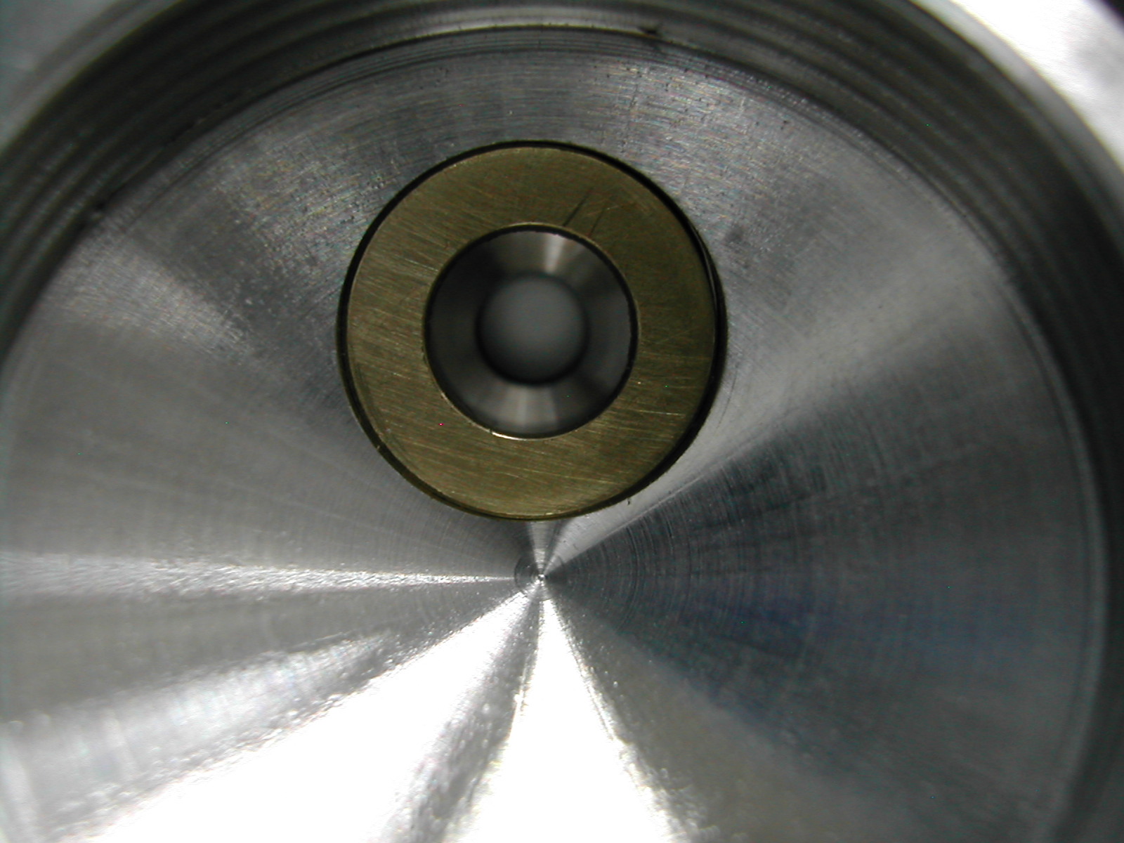
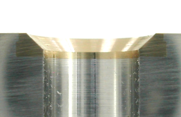 Here’s the test piece after milling it down the centerline and polishing it.
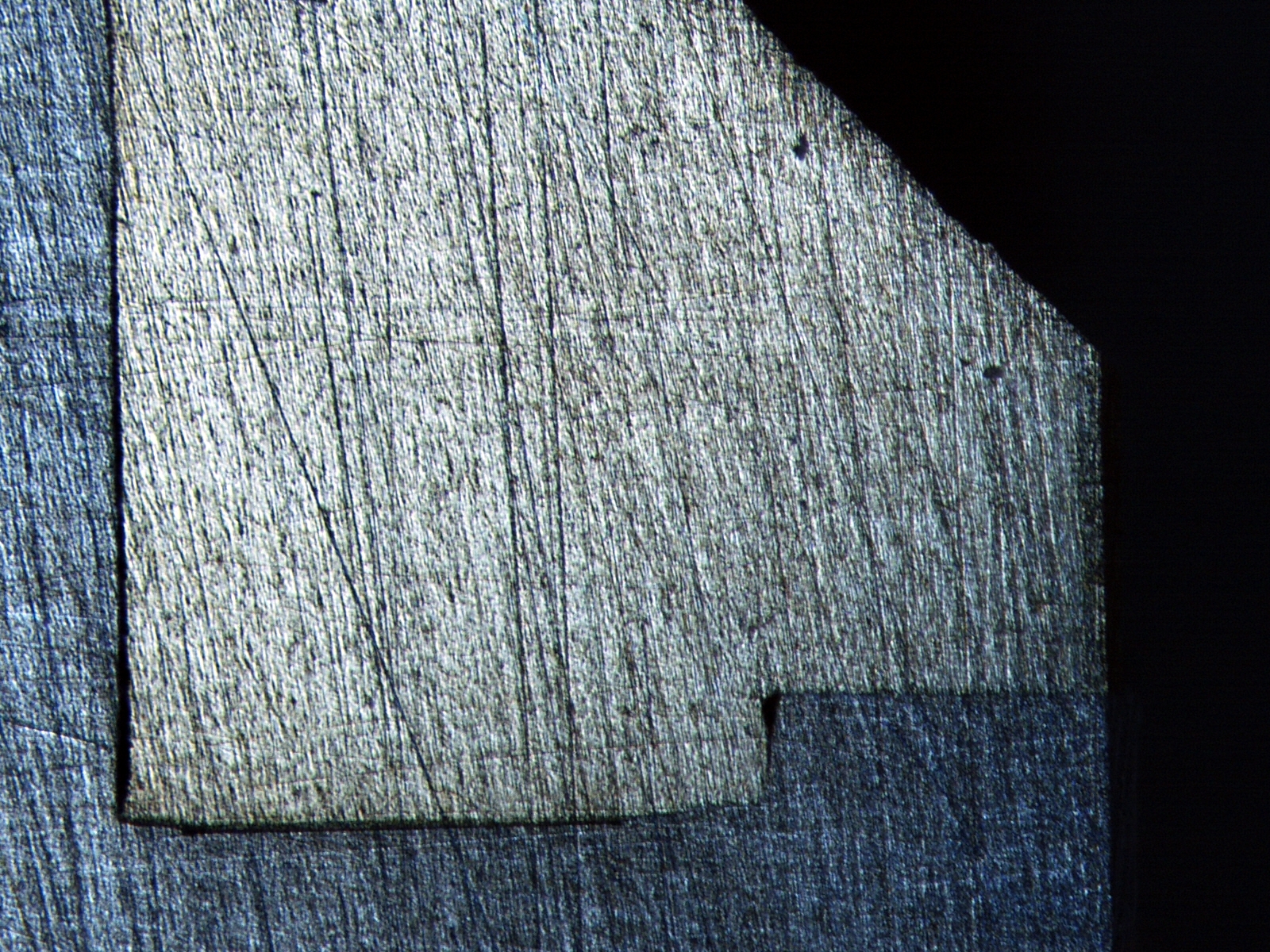 And here’s the same test part at 50X magnification. While it swaged completely out to the 0.470″ diameter in the aluminum part, it did not completely fill the undercut.
I will say the swaging was still good enough to withstand the subsequent boring with the ball-nose endmill and chamfering without spinning in the aluminum, but I still wished it would have completely filled the undercut.
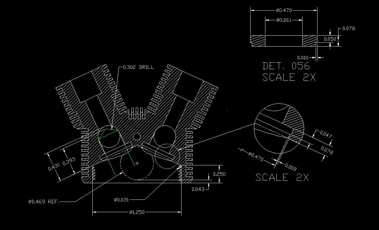 So, here’s the 056 Head AutoCAD Drawing (AutoCAD 2010) of the final design. I added 0.001″ interference radially, and 0.003″ in thickness.
 To make the valve seats, I started by working up to a 0.261″ (letter “G”) drill. I needed 22 seats plus a few extra so I made my seats in three batches, drilling about 1″ deep for each batch.
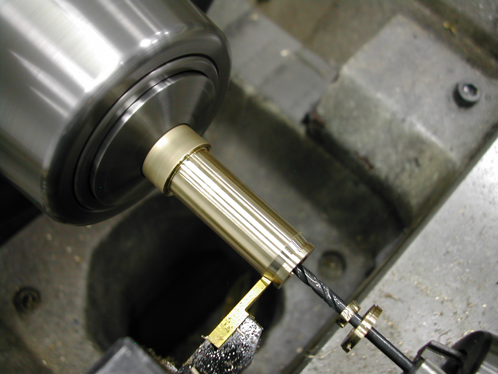
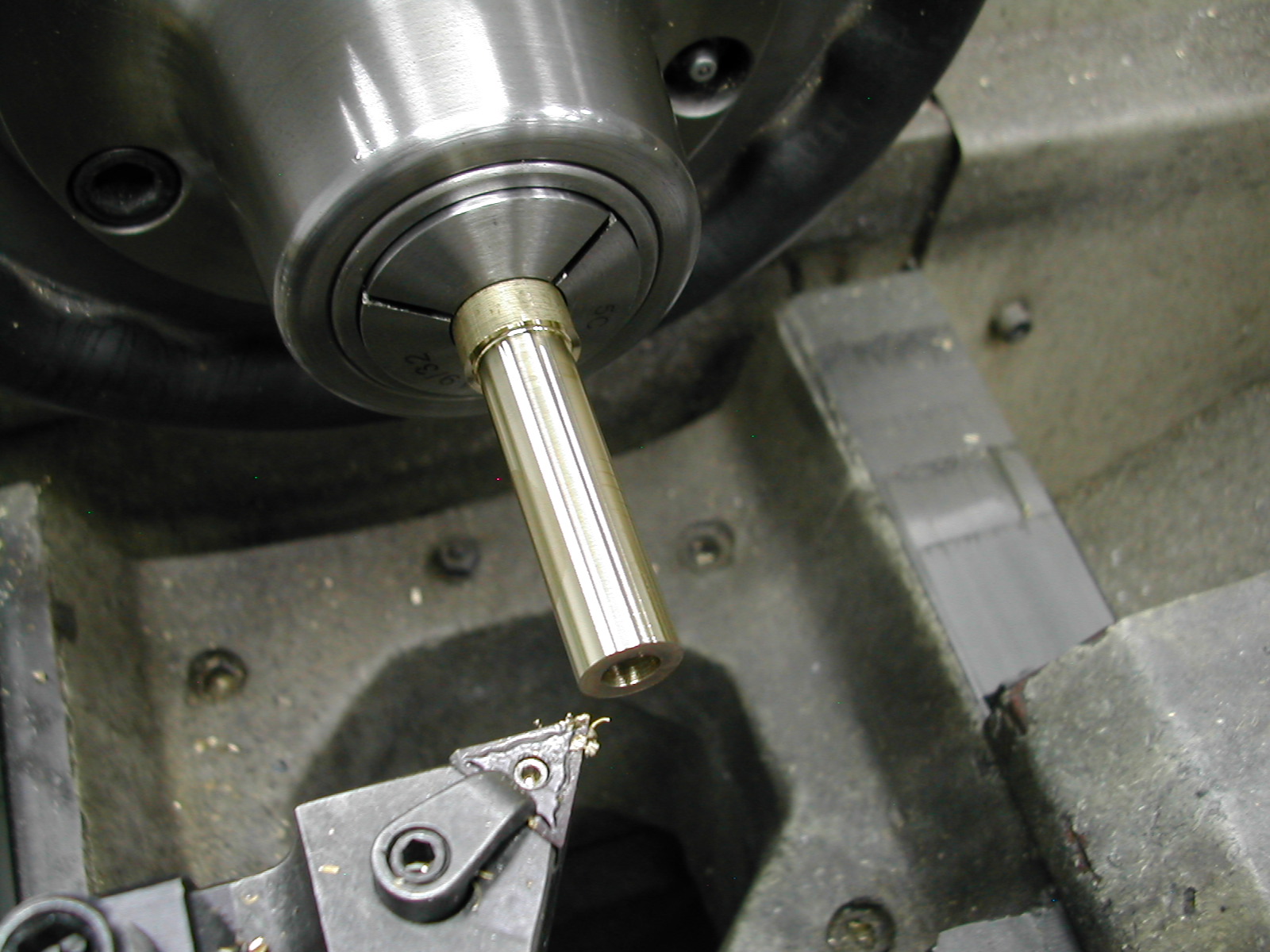 I rough turned the O.D. down to 0.48″ with a length corresponding to the drill depth.
After rough turning, everything else was done with a thin parting tool ground with a slight angle on the cutting edge. My parting tool was 2.00mm wide so the Y coordinates that follow will need to be adjusted to fit a different width tool.
First step was to take a minimal face cut to clean up and zero the Y axis.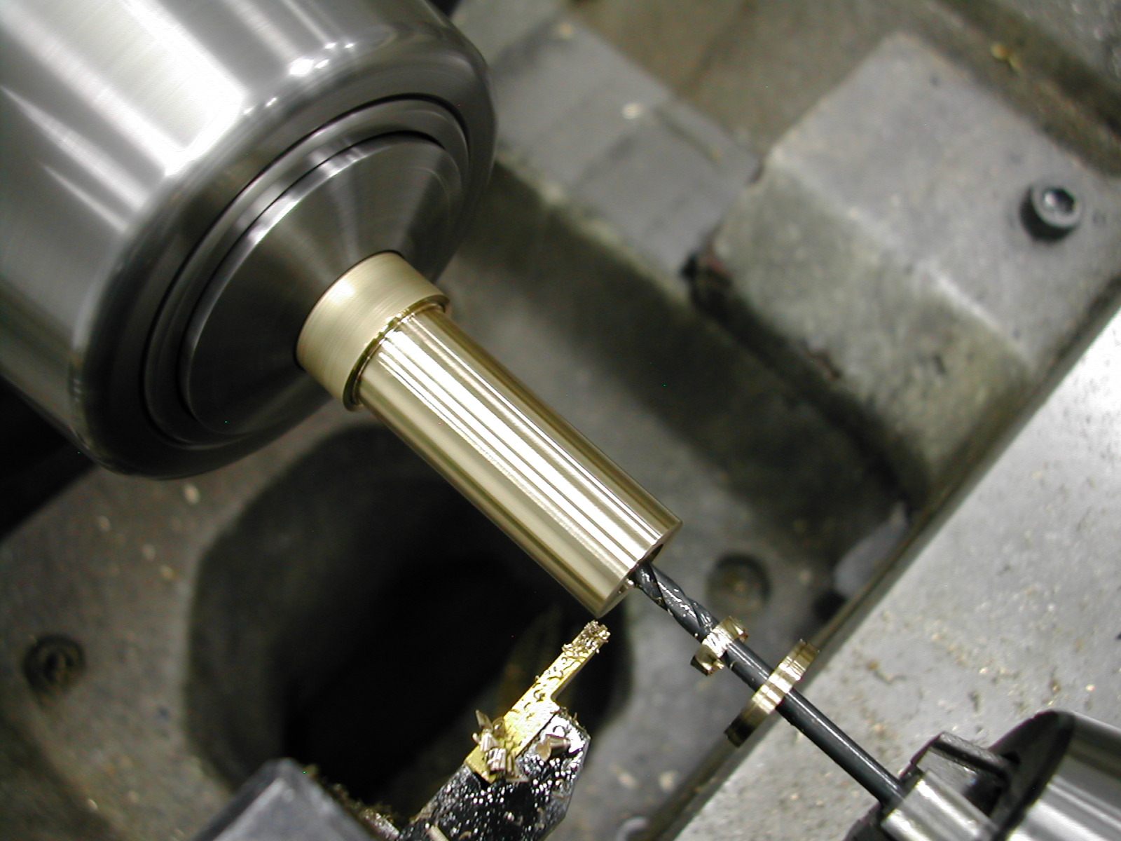
Step 2 – turn 0.470″ diameter to Y=0.129″ (0.050″ + 2mm).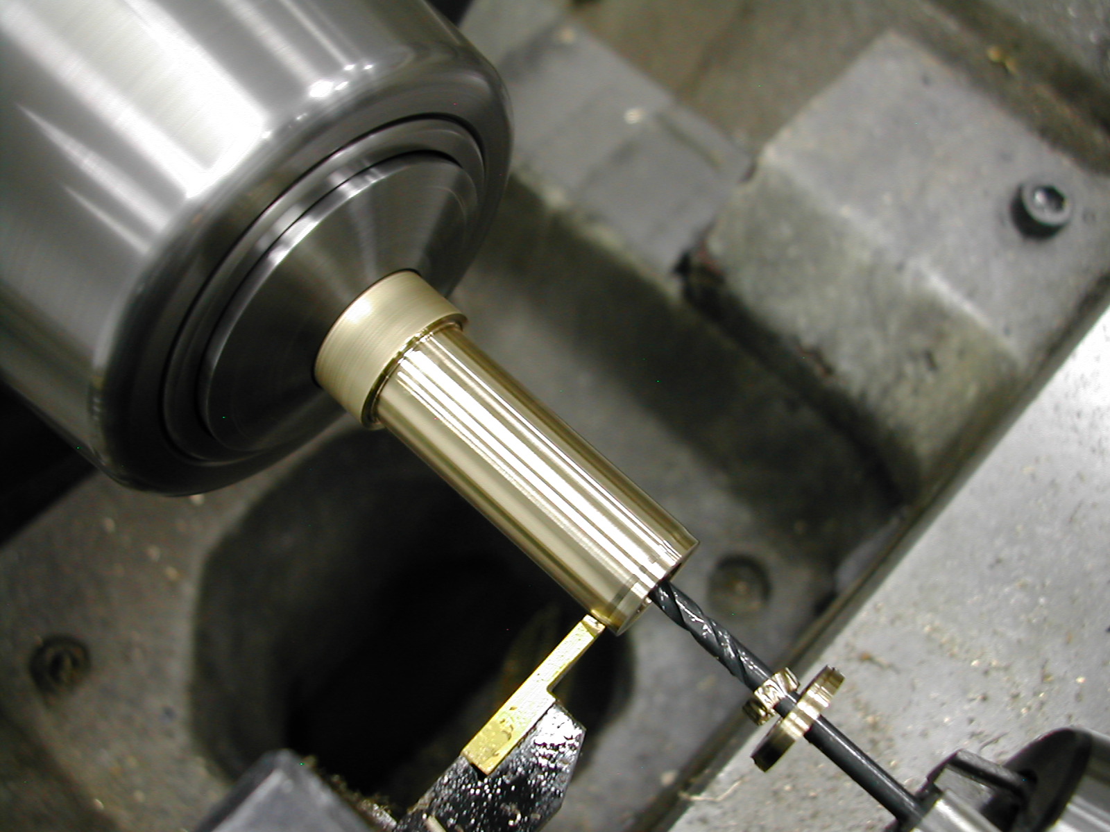
Step 3 – feed in 0.020″ on the diameter and then feed Y to 0.157″.
The last step was to part off at 0.157″ (0.078″ + 2mm).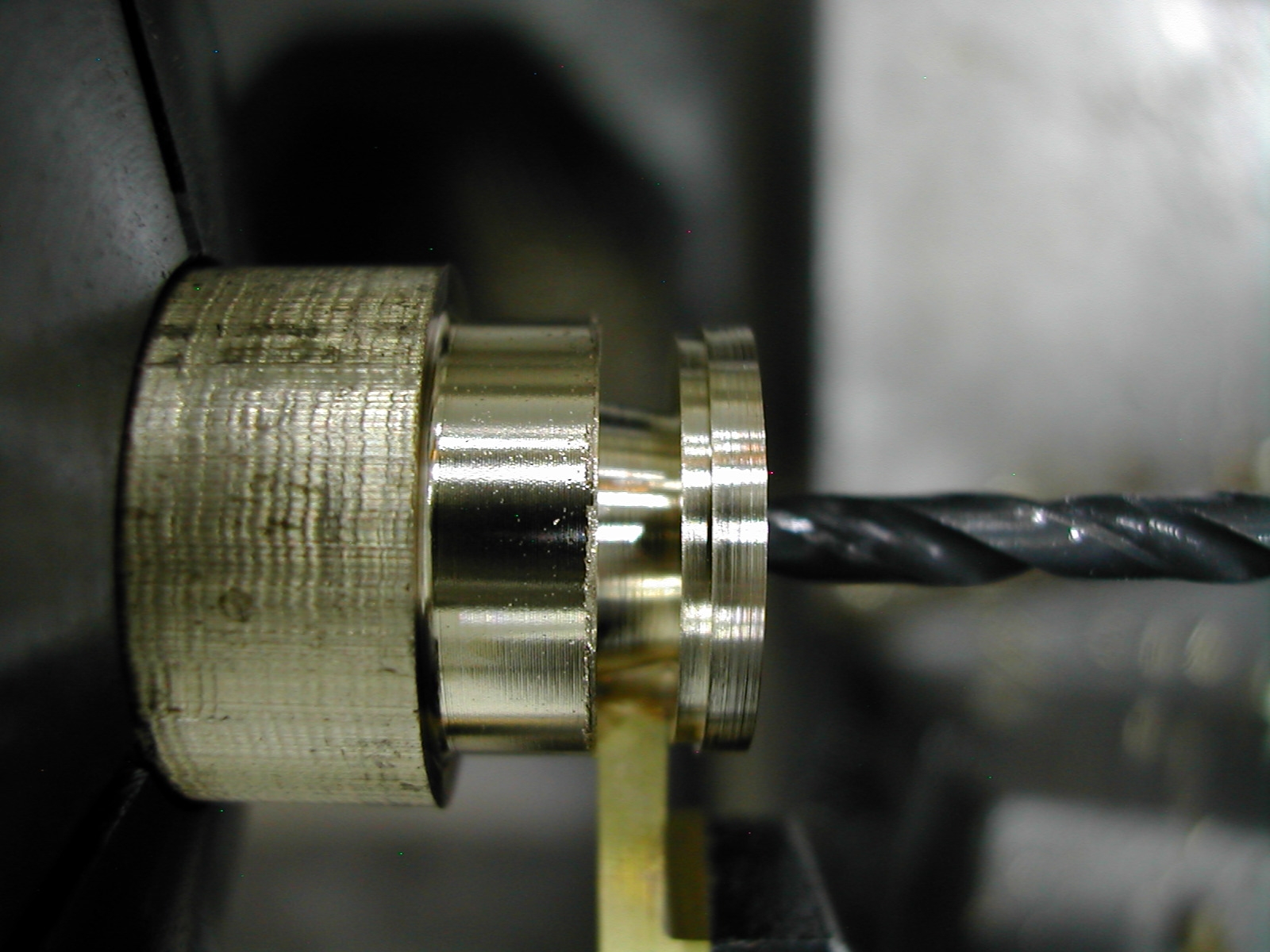
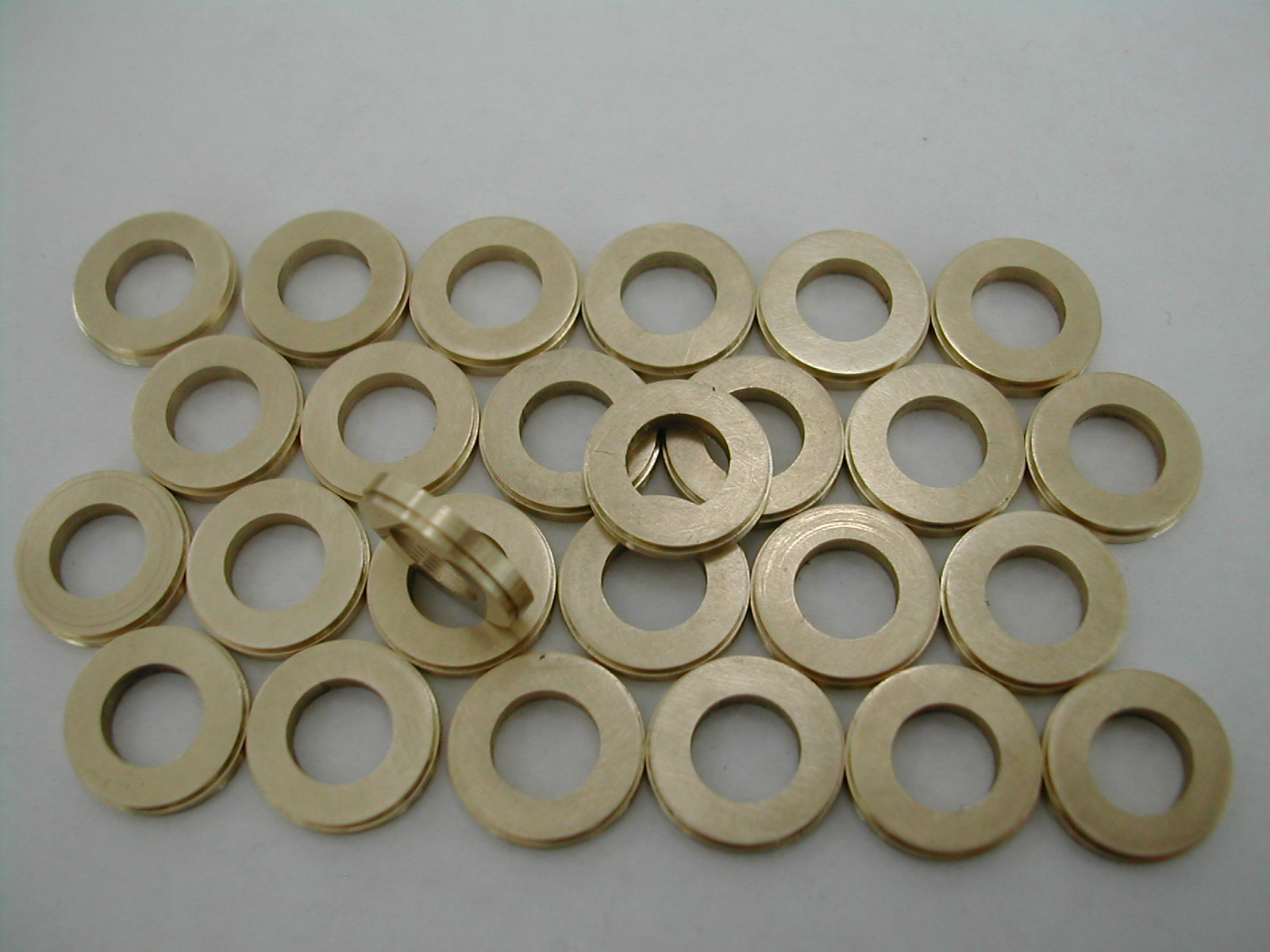 Repeat the above as needed and then lightly lap the two outside faces on 600-grit paper to remove any turning marks. Don’t attempt to do any further deburring as it’s not necessary and we really don’t want to break any of the outside edges – we want to completely fill the cavity in the head all the way into the corners.
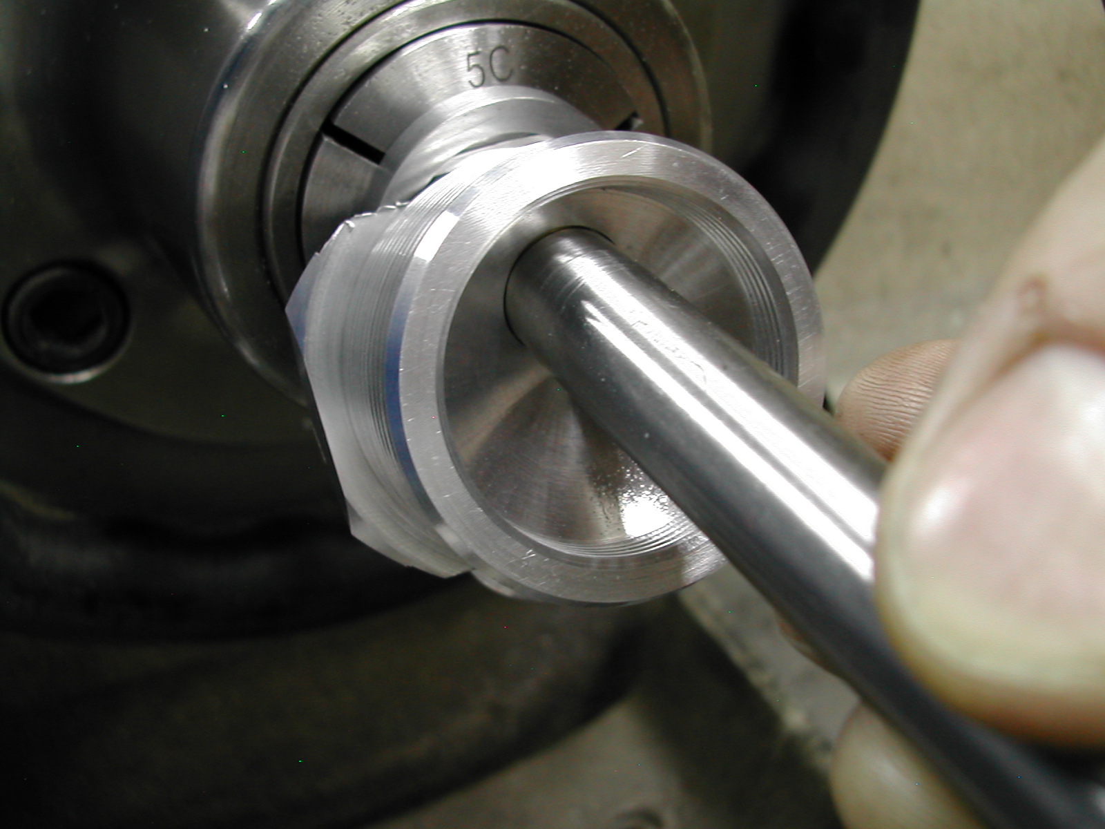 To install the valve seats, Make sure the cavity and seat are clean then use the piloted tool to tap the seat all the way to the bottom of the cavity.
Here is the seat inserted into the cavity – note the gap around the outside.
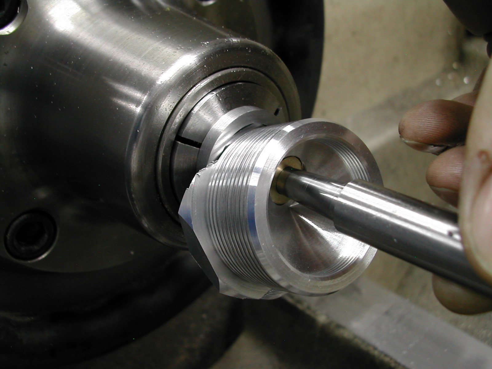 The tapered swaging tool is then inserted into the valve seat. Use multiple firm taps until the tool bottoms out in the 0.302″ drilled hole. It will take some significant force to expand the valve seat and the swage tool must be hardened or you will swage rings into the tool rendering it useless.
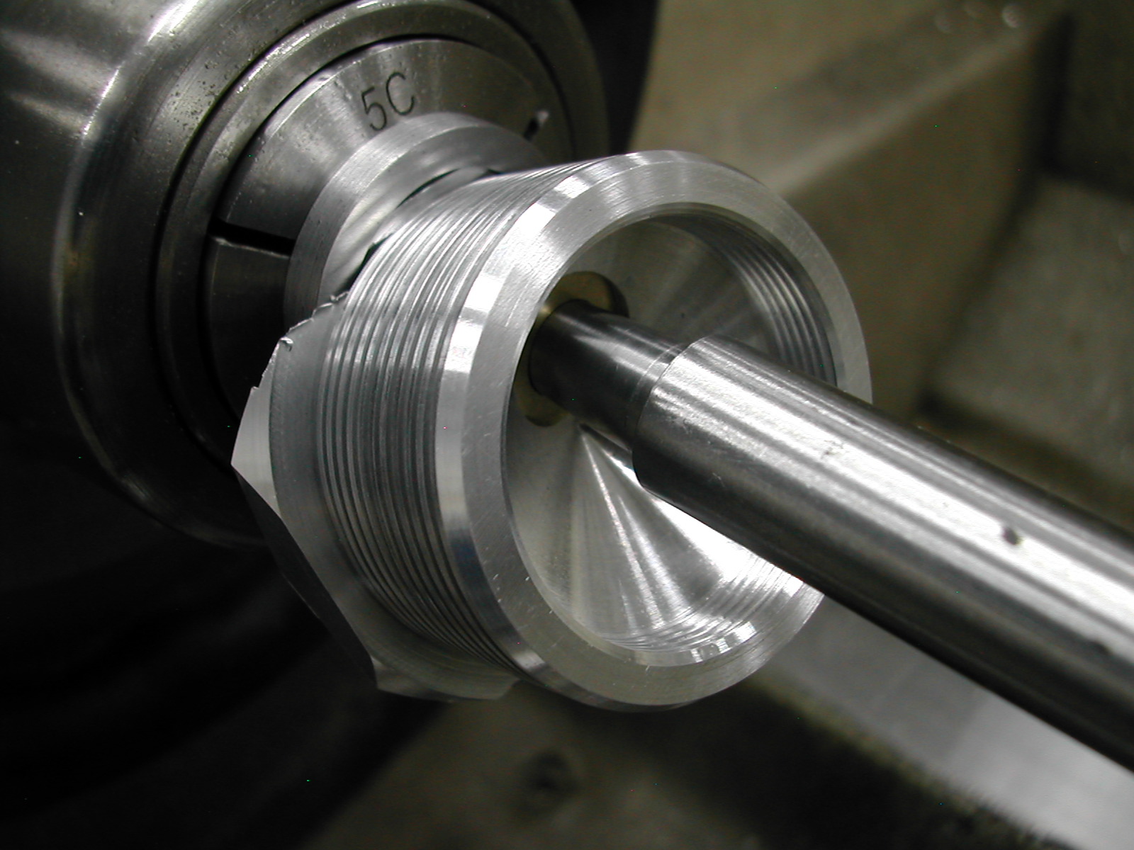 The swage tool has been driven as far as it will go. You will notice a distinct change in tone when the tool bottoms out in the head. If you polished the tool well enough, a few light taps on the side of the tool while pulling on it at the same time will break it loose from the insert.
That’s it. The valve insert is now fully swaged it place. We’ll bore the center hole to 0.312″ at the same time we create the valve plenum in the head. This will insure there is no mismatch between the seat and head which could disturb the air flow.
The 45° chamfer will also be done in place as well, assuring it is concentric with the valve guide.
Disclaimer and License
All material, including the CAD drawings, relating to the construction of the Hodgson Radial presented on this site is free to use any way you see fit. However, no guarantees are made regarding the accuracy or correctness of the material presented here.
Links Used On This Page
(CAD drawings are in AutoCAD 2010 Format)