
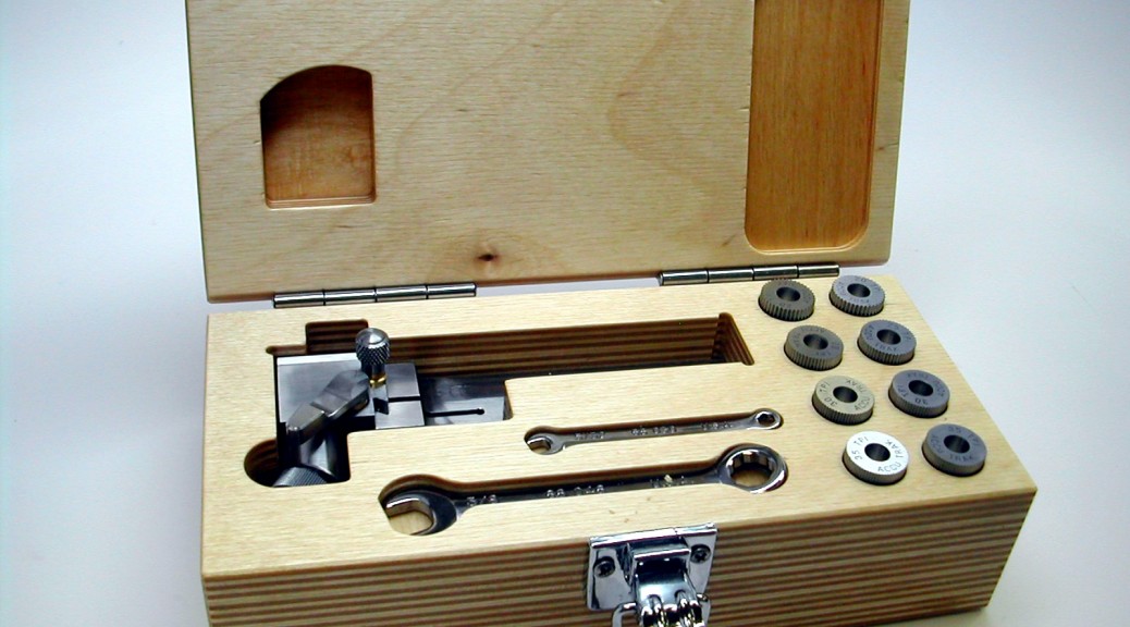
The Cut Knurling Tool
It seems like I’m always making a tool to make a tool to make a tool… Then again that’s why we all started with the hobby isn’t it? I finally have some time to get back on the Quorn project and it looks like I’ll be needing to knurl a few pieces. Fortunately, or unfortunately as my wife sees it, the “Home Shop Machinist” magazine recently ran a 5-part article on a cut-type knurling tool. The article started in the March/April 2010 issue and ran through Nov/Dec 2010. In this article Michael Ward describes a knurling tool that creates perfect, full-depth knurls without being hard on the lathe. It looks fabulous and if it works even half as well as described, all the better! Who could pass up an opportunity like that?
Certainly not me! This series of pages documents my building of Michael’s knurling tool with, as always, a few “improvements” of my own thrown in. In addition, I’ve included a full SolidWorks 2013 model of the tool as I built it. It’s probably not enough for you to build your own without the article so I’d do some searching for back issues before attempting this. With the article in hand, let’s get started.
One of the improvements I made, based on availability of material as much as desire, was to make the knurling tool out of Stainless Steel. I’ve been doing a lot of work on medical devices lately so that means that I have a lot of 17-4 pre-heat-treated stock around. This material is H1150 temper, around Rc33 in hardness, and machines beautifully. The only downside is that most of my stock is rounds. So always the first task is to square it up.
I’ve changed Michael’s order of making the parts based on a rule I learned long ago. When you need close fitting parts, it’s always easier to fit a male feature to a female feature than the other way around. With that thought to guide me, below follows the parts in the order I made them.
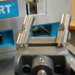
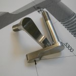
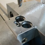 Details 06 & 07, the Tool Holder Arm and Head
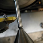
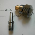 Details 03 & 05, the Spindle and Wheel Nut
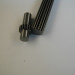 Details 19 & 20, the Small and Large Gears
 Details 13-15, the Locking Levers and Screws
 Details 9-11, the Height Adjustment Mechanism
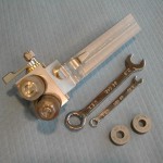 Final Assembly, fitting the levers, making the knobs, and assembling the tool, including Details 12, 16, & 21.
Disclaimer and License
All material, including the CAD drawings, relating to the construction of the Cut Knurling Tool presented on this site is free to use any way you see fit. However, no guarantees are made regarding the accuracy or correctness of the material presented here.
Downloads
(CAD drawings are in SolidWorks 2013 Format)