
Details 13-15, the Locking Levers and Screws
 I decided to challenge myself here a little and instead of making the two piece lever/screw combinations as presented in the article, I chose to make mine in a single piece and again out of the hardened Stainless Steel. So this task begins by knocking down some round stock. My blanks will be 2.5″ long – that’s 3/4″ longer than the Spindle Housing Lock Screw to give me something to chuck on in the lathe.
 The stock was then split into two blanks in the bandsaw.
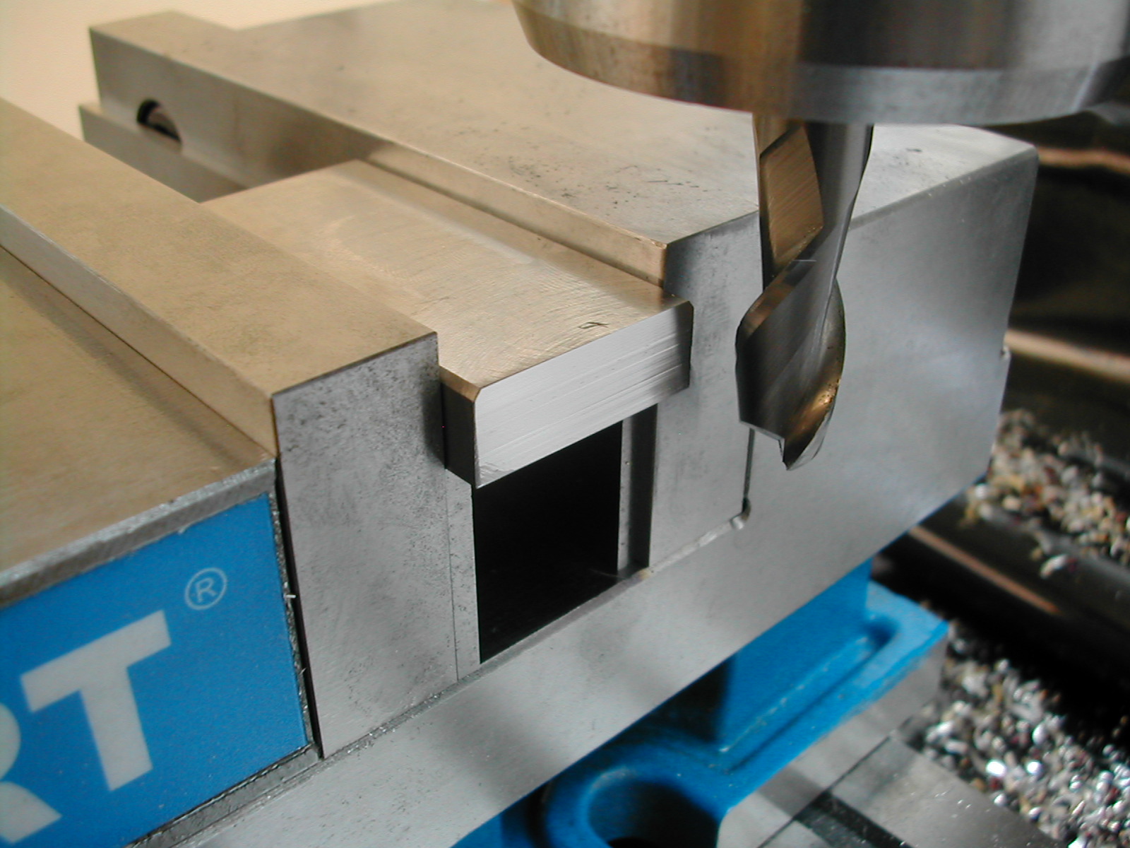 The two blanks were then faced to 0.435″ thick and one end was cleaned-up and milled square. This was so I would not have to face it off in the lathe before putting my center hole in.
 A trip back to the bandsaw removed most of the waste, and the mill was used to cut the sawn surface down to 0.435″. Having milled this stub square will facilitate indicating it in in the 4-jaw chuck on the lathe.
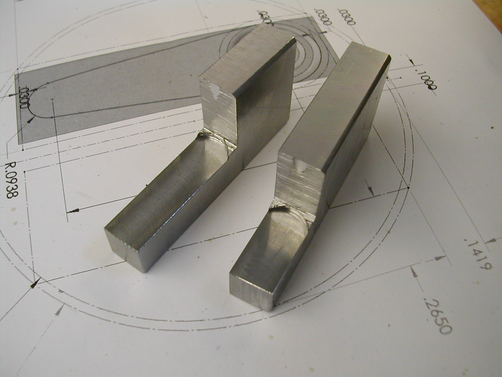 The two blanks are ready for the lathe. The shank should be about 0.060″ oversize so it’s not incredibly critical to get it exactly centered in the lathe. The remaining sawn surface will get faced in the lathe to form the bottom surface of the lever.
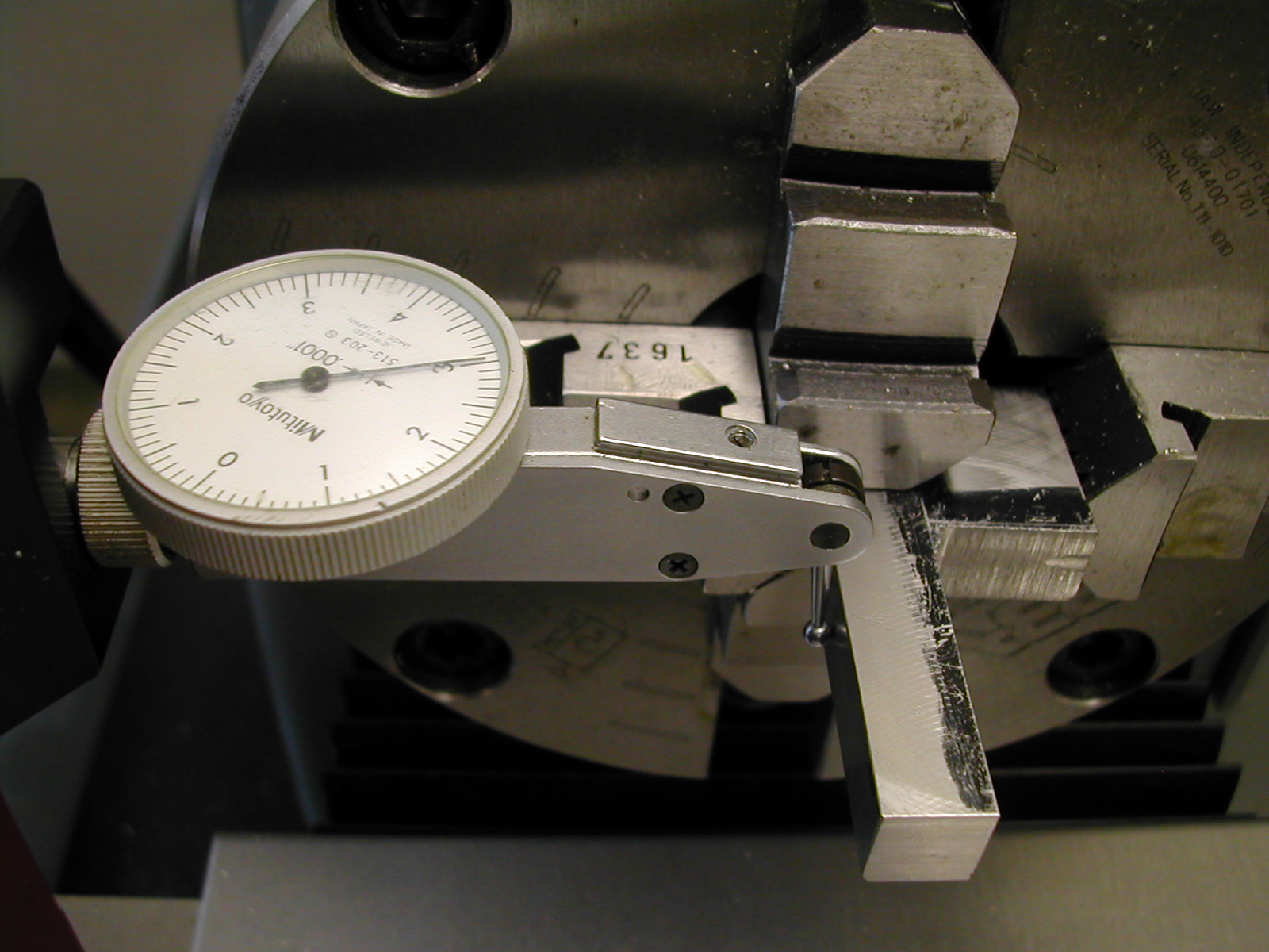 Starting on the longer Spindle Housing Lock Screw, the square shank portion was indicated in using an independent 4-jaw chuck. A scale would have worked just as well here since there was 0.03″ per side to work with.
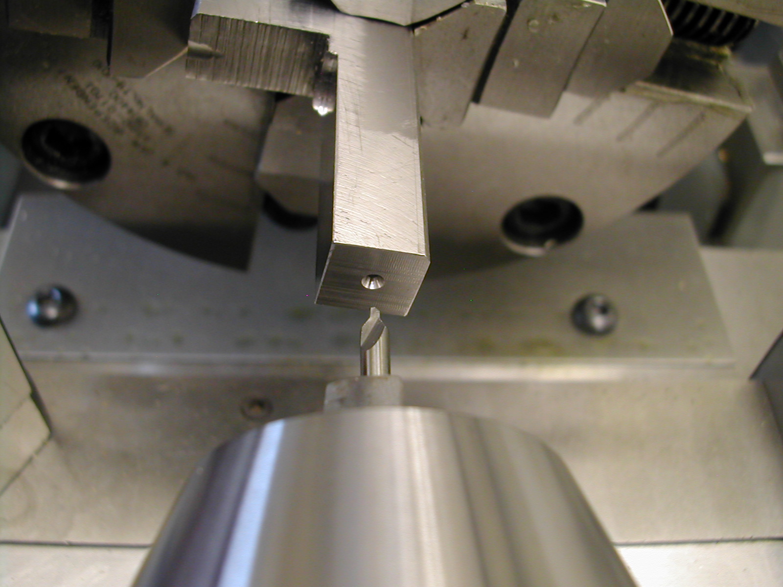 Now I can add a center hole. By milling this surface earlier, I didn’t have to try to face this unsupported.
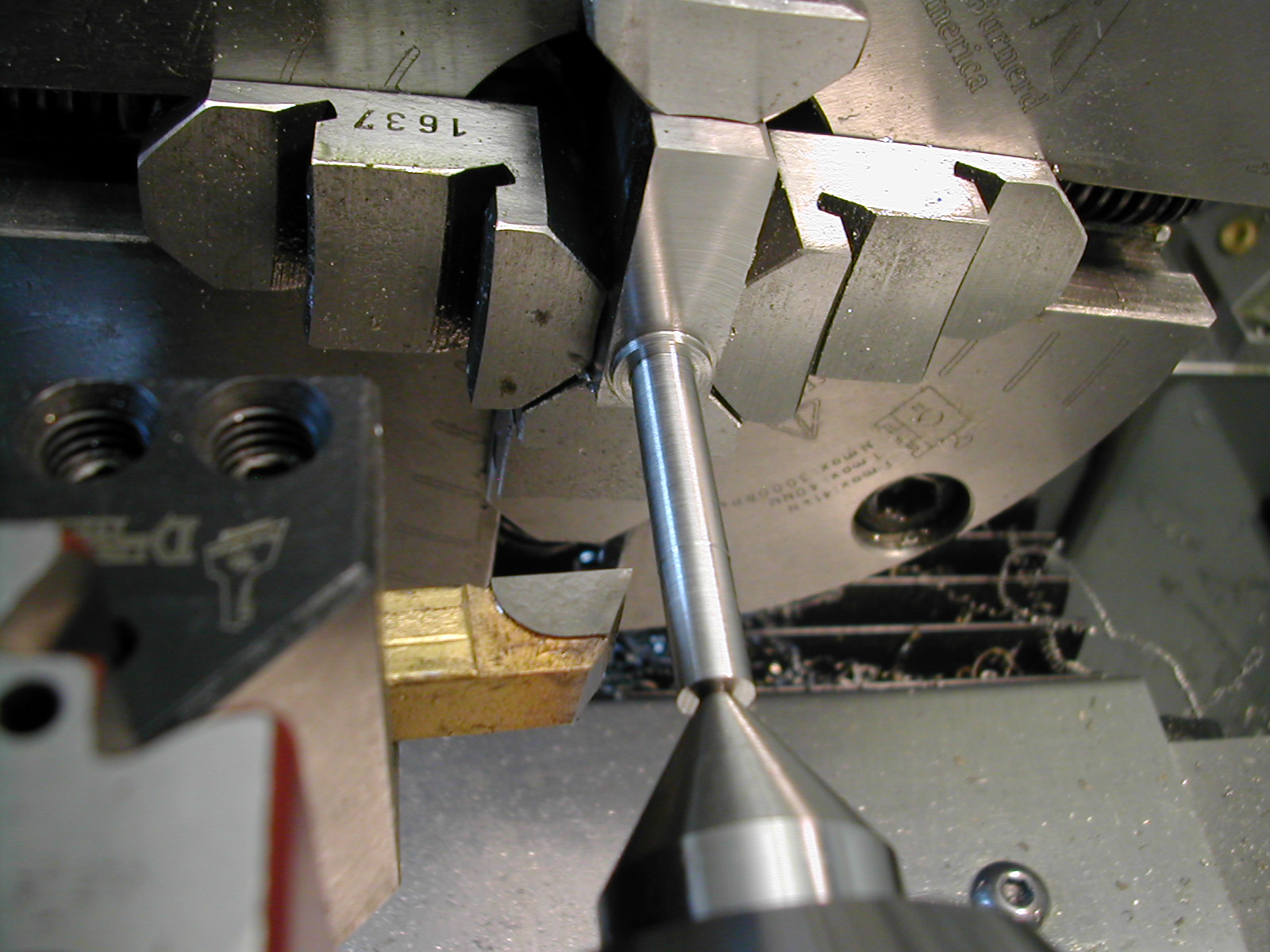 With the center in place, its a simple job to turn the screw and face the bottom of the lever. While the shank portion of the screw was turned to 0.250″, here I’ve just reduced the area that will be threaded to ø0.246″.
 A few passes of the threading tool results in a class 2A 1/4-28 UNF thread.
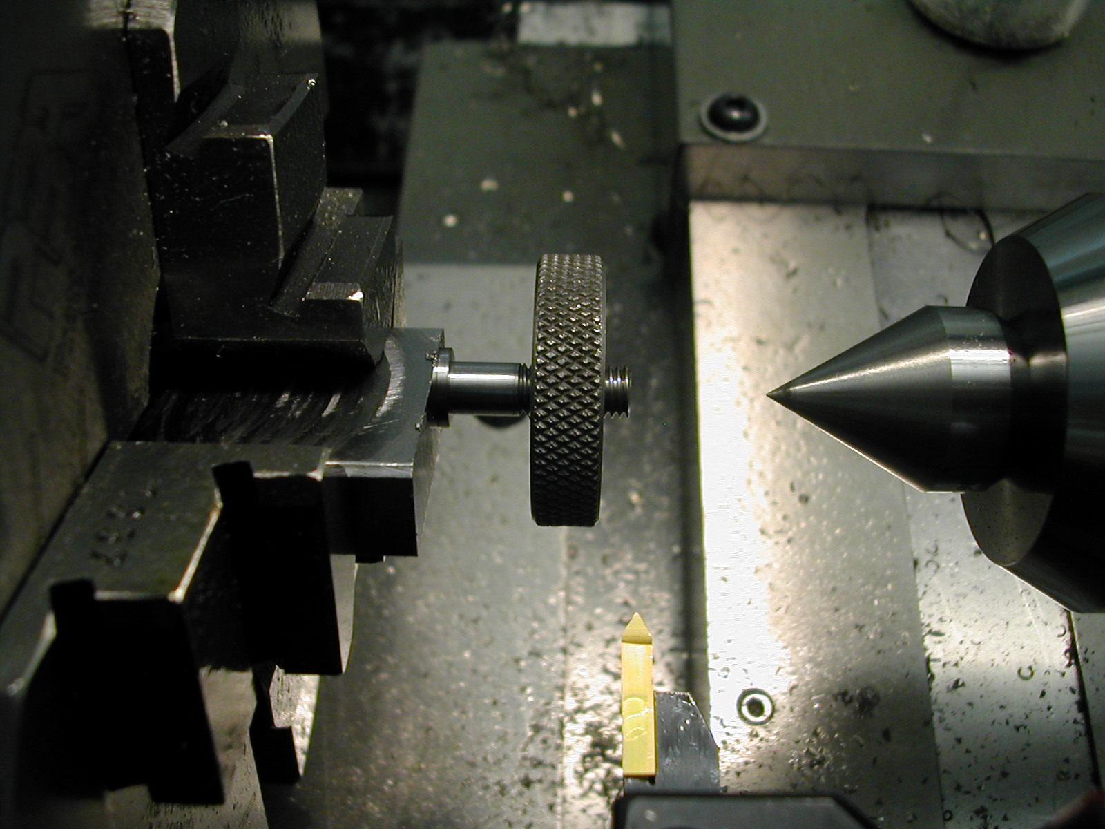 The process was then repeated on the Height Adjust Lock Lever and ended at this point with a thread gauge check.
 The next step will be to bandsaw off the excess we used for chucking in the lathe.
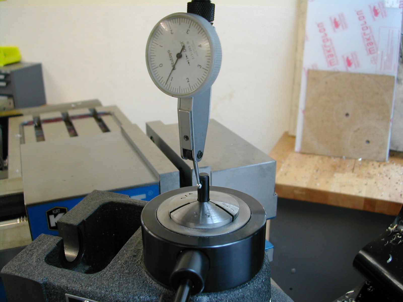 To get started on milling the lever portion on the lock screws, a collet vise was installed on the mill and a dowel pin was used to indicate the collet chuck since the shank portion of the levers will not be accessible when they are clamped up.
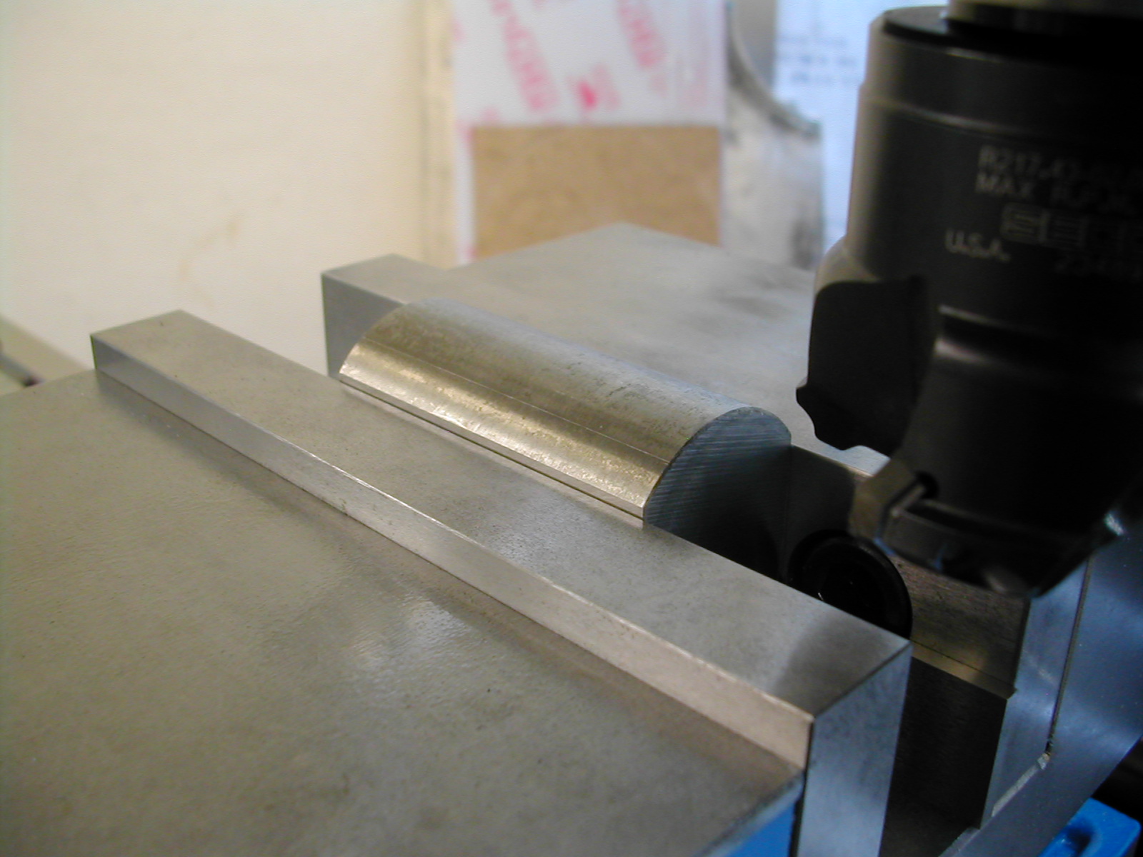
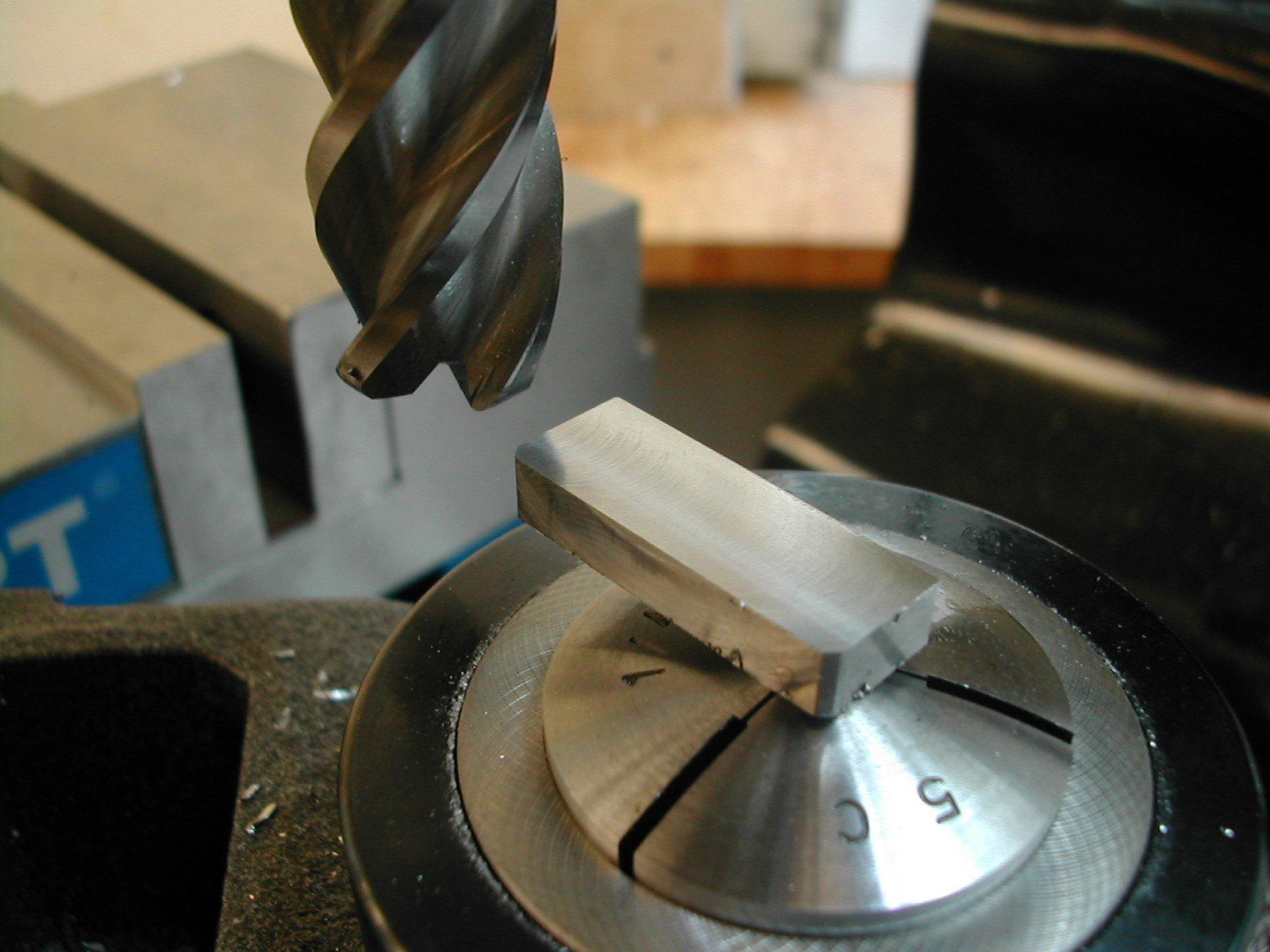 With the lever clamped and visually squared up with the mill axis, the lever portion was milled to thickness.
 And then profiled. I profiled before sculpting the top surface because I wanted the overhung portion of the lever as stiff as possible to reduce chattering when cutting the small end.
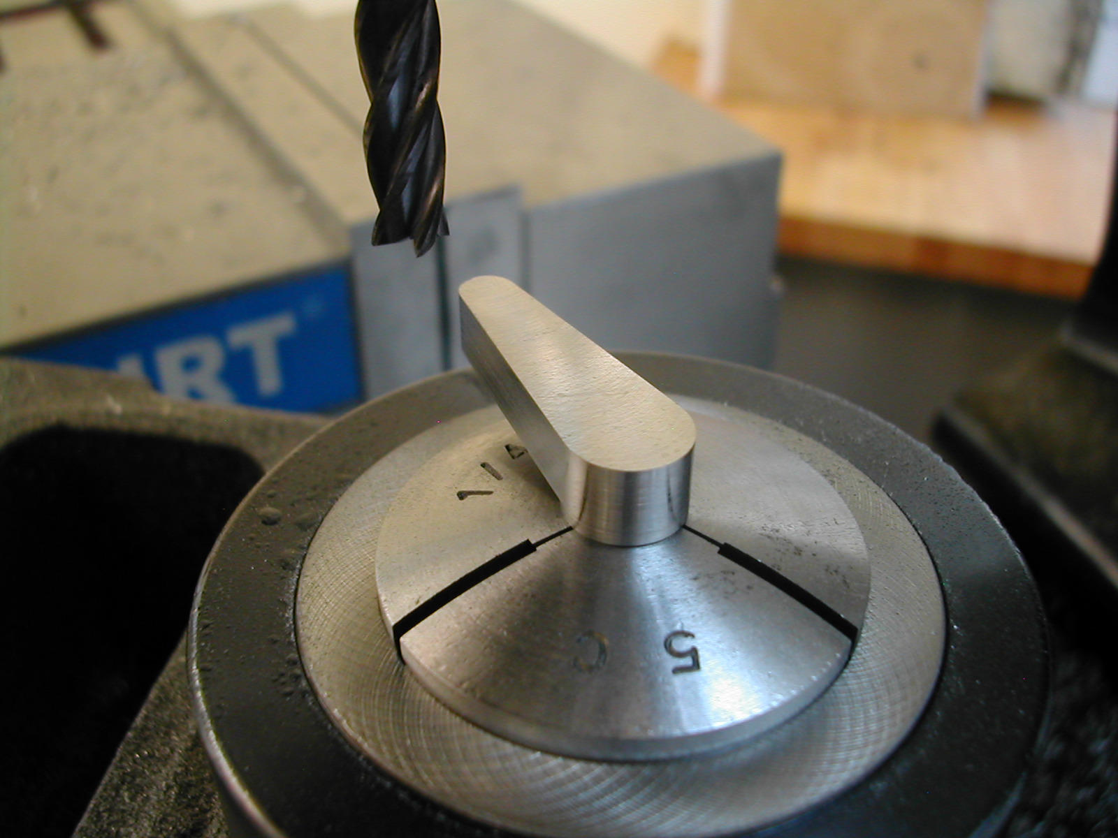
 Now that the lever is profiled, we can reduce the center thickness and add in the radius. Small cuts were taken in hopes that it would not grab and spin in the collet.
 The last step before deburring was to add a small chamfer on the top of the pad.
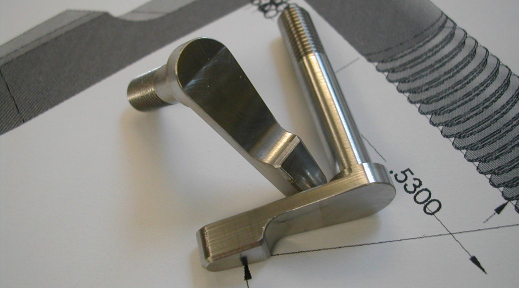
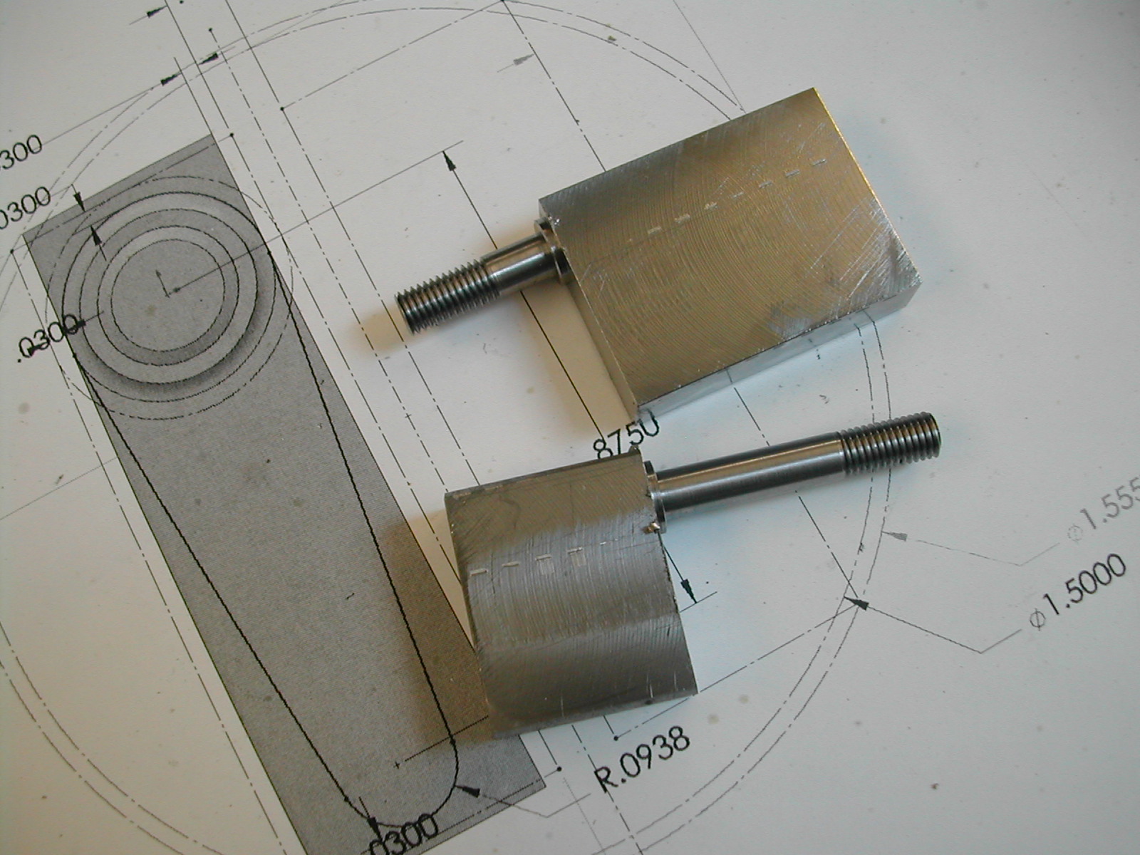
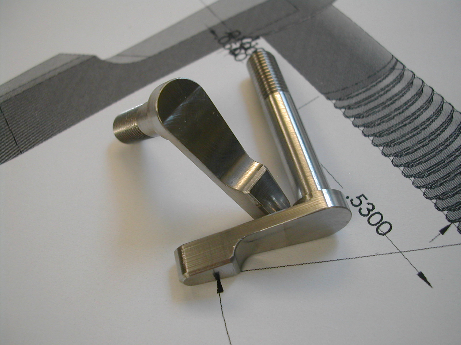 The two combined levers and screws ready to be installed.
Disclaimer and License
All material, including the CAD drawings, relating to the construction of the Cut Knurling Tool presented on this site is free to use any way you see fit. However, no guarantees are made regarding the accuracy or correctness of the material presented here.
Downloads
(CAD drawings are in SolidWorks 2013 Format)