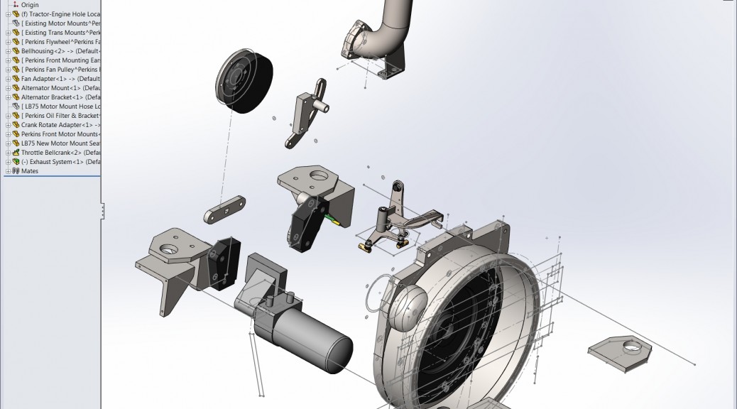
SolidWorks 2014 Perkins Fabricated Parts (17.5M)
In addition to the bellhousing, quite a number of other parts needed to be fabricated before the engine was ready to be installed. The Perkins came without electrics, and the old Iveco starter would not fit the new engine. A new starter was purchased, but I was able to use the old alternator by fabricating a new mount.
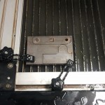 The alternator mount was cut on the waterjet out of 3/4” CRS. While on the waterjet, I cut a little crank adapter to allow rotating the crankshaft with a socket wrench for use when attaching the transmission.
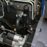 A fan adapter was made so that I could use the old set of fan blades. The fuel injection pump on the Perkins was on the opposite side from the Iveco so the tractor throttle cable was going to be too short. The fix for that was a small bellcrank to route the throttle cable behind the engine block. The bellcrank also served to adjust the throttle cable travel to match the new injector pump travel.
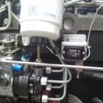 It took a while to locate the mating connector for the Delphi injection pump fuel cutoff, but it’s a Pico 5621PT Fuel Injector Repair Pigtail Connector. I got mine off eBay. I made a wiring harness for the fuel cutoff as well as adding a Hobbs hour meter into the fuel circuit. The new hour meter will track usage for the new engine while the old meter in the cab will be accurate for the rest of the tractor.
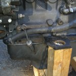 The final issue to overcome was the motor mount locations. The rear pair of mounts on the transmission were to remain the same. The front ones had to move for a couple of reasons. First, the new oil filter location was directly on top of the existing left front motor mount, and second the stress block Perkins was set up with mounting ears on the front of the crankcase, not midway at the center of mass like the old Iveco.
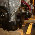 So, a new pair of front motor mounts was fabricated from some ½”x4” angle iron using the top plate from the old engine mounts. The new mounts bolt up to the ears cast onto the front of the Perkins block. A new pair of frame mounts was also fabricated from the same ½”x4” angle iron.
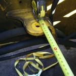 The old frame mounts in the tractor were carefully measured, entered into SolidWorks, and verified with the measurements taken of the engine/transmission mount locations and the CAD model. All three sets of measurements correlated within 1mm, well within the accuracy needed.
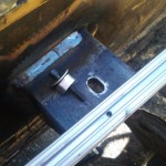 A positioning
 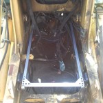 framework based on 80/20 aluminum extrusions was fabricated. This framework used spacers to locate in the existing slotted rear frame mount holes (transmission) as well as the slots in the new frame mounts, and rested on the old front frame mounts to position the new mounts for welding in the backhoe frame.
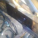 Once the new front frame mounts were in place, the old ones were cut out and the areas repainted. The old frame mounts served double duty acting as hose guides as can be seen by the old left front mount. With the old mounts removed, I’ll need to add some new hose supports before I install the new engine.

