
- Inspiration and Design
- Machining Blanks for Hones
- Cut Out Hones and Machine
- Finish External Hone Project
Sawing the Shapes
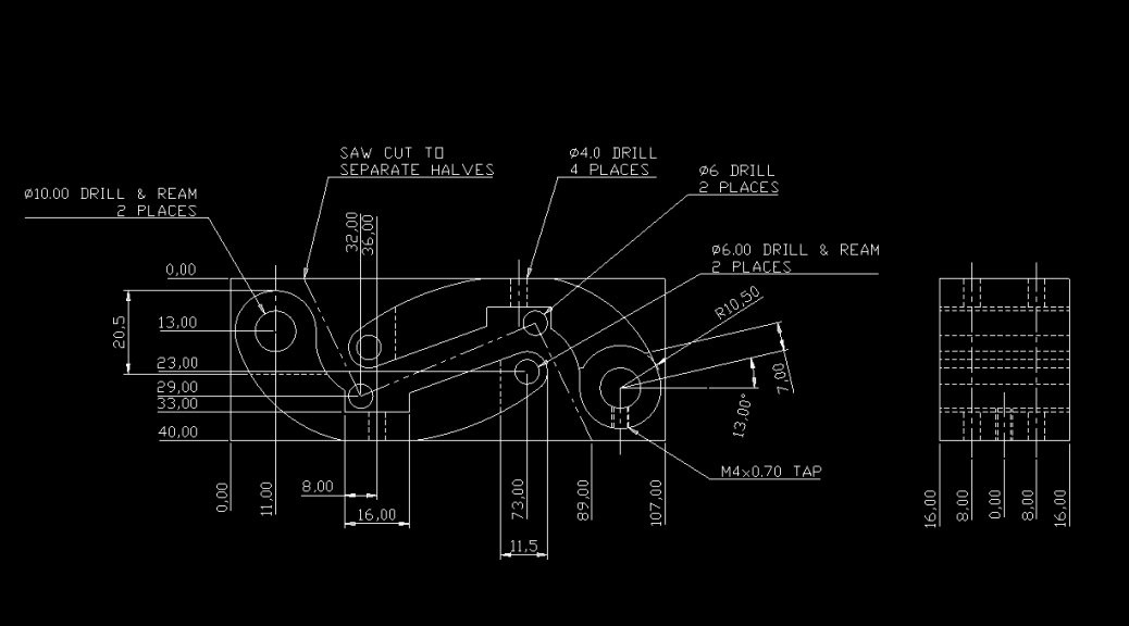
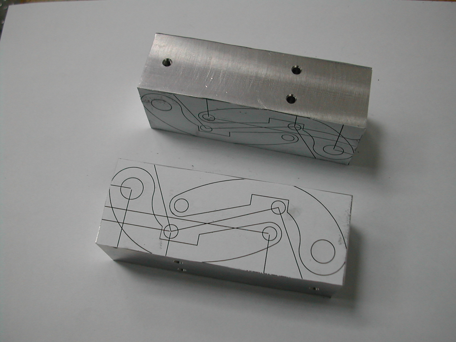 To make the sawing operation a little easier, I printed out copies of my stock plan and glued them to the stock.
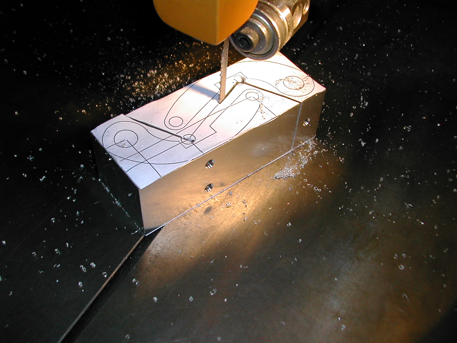 The blocks are then split at the bandsaw. Don’t remove any of the waste at this point. We’ll use the orthogonal surfaces for location in future operations.
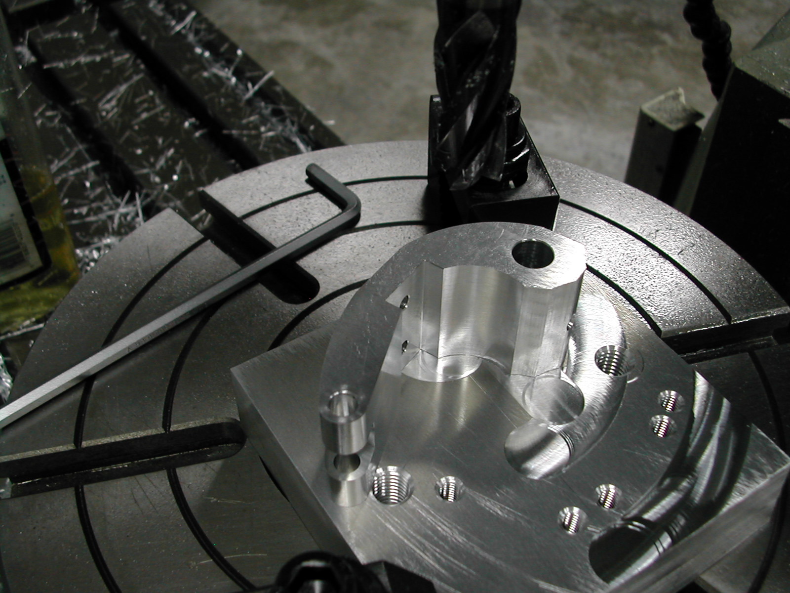
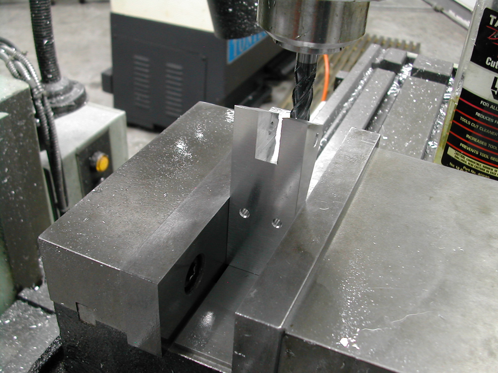 Here, I’m using an 8mm endmill exactly on center to rough out the adjuster block pockets. Once the pocket is roughed to depth, I’ll step over to make a 1mm climb cut to finish one side.
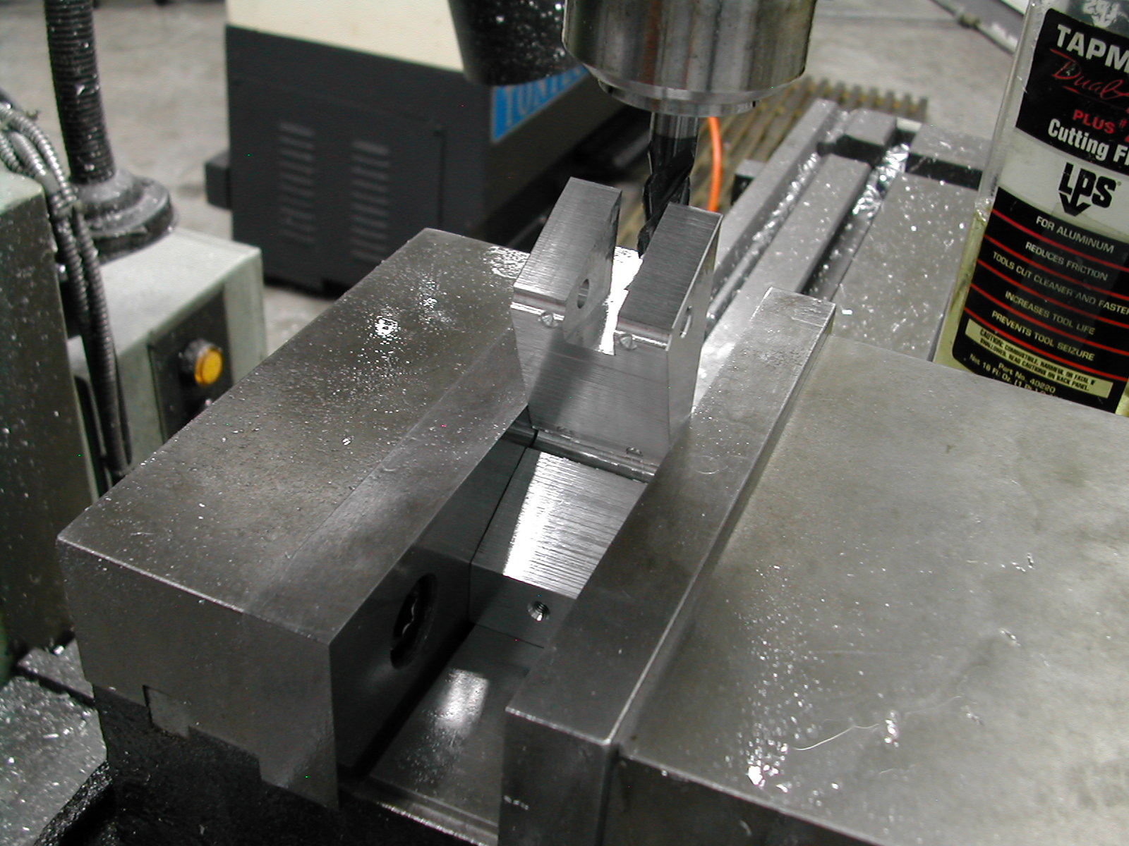 Without moving the cutter back to center, the part is flipped and the finish cut is made on the other side. This insures that the slot is centered in the blank.
On your first slot, you’ll need to work up the 1mm dimension, flipping and cutting the other side and perhaps repeating this process a few times to insure a nice slip fit on your 10mm cubes you made previously. Make sure your cubes rotate freely in the slot when installed on the axle.
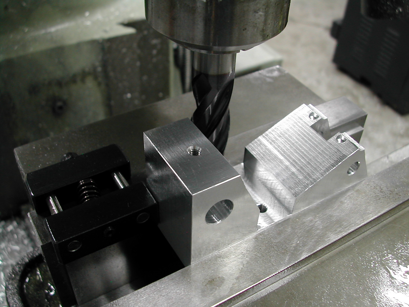 Next cut the anvil pockets. Since we have not made the anvils at this point, the actual width is not critical, but it is important that all of the anvil pockets be the same width and centered on the retention screw holes.
 At this point, you can head back to the bandsaw and remove the excess material from around the profile. Leave about a millimeter for cleanup.
 We’ll need a couple of bushing to hold our parts on the rotary table fixture we’ll be using later. From some scrap make one bushing 10mm in diameter by 15mm long with a 6mm clearance hole through, and a headed bushing with a 10mm diameter with a 31mm long shank and a 6mm through hole. The head on the bushing should be 16-18mm in diameter and both of these should be a nice slip fit in the 10mm axle holes.
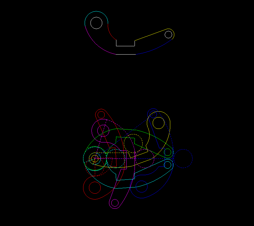 This next image looks a little complicated, but it’s rather simple. At the top of the image, each color segment on the profile corresponds with a single cut and also with the same color profile on the bottom which shows the position on our rotary table fixture and the endmill starting location.
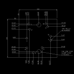 This is the actual rotary table fixture. The plan presented right is also available for download .
 Preparing the Rotary Table Fixture
- Mount rotary table on mill and indicate center
- Rotate table to 0°00′ and lock in place
- Mount tooling plate on rotary table centered top to bottom and 20mm from left edge
- Drill & tap 10 M6 holes
- Drill & tap two holes to fit step clamp stud
 Arc #1 – the blue arc in the plan
- Mount suitable end mill (I used 16mm x 40LOC)
- Set rotary table to 0°00′
- Mount frame with large end at hole #6 w/flanged bushing, small end at hole #10, offset to right
- Starting from right of part, Y at 0.00, move X axis to 68.00mm + 1/2 cutter dia + 0.1mm stock
- Rotate table CW until cutter clears small end of frame (appx 40°) (conventional cut)
- Move X to 68.00mm + 1/2 cutter dia and cut CCW back to 0° (finishing climb cut)
- Repeat 2-6 for all frames
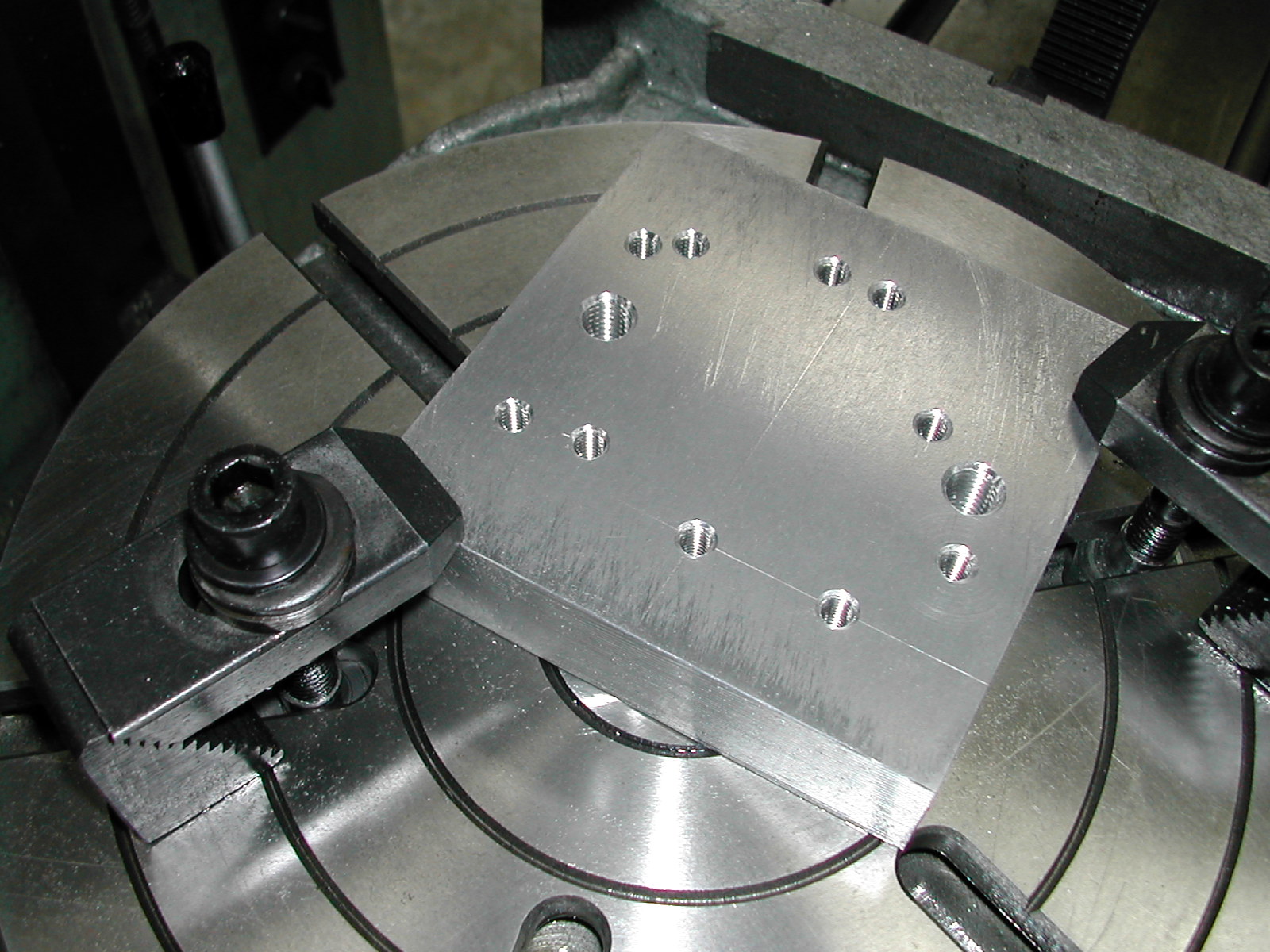
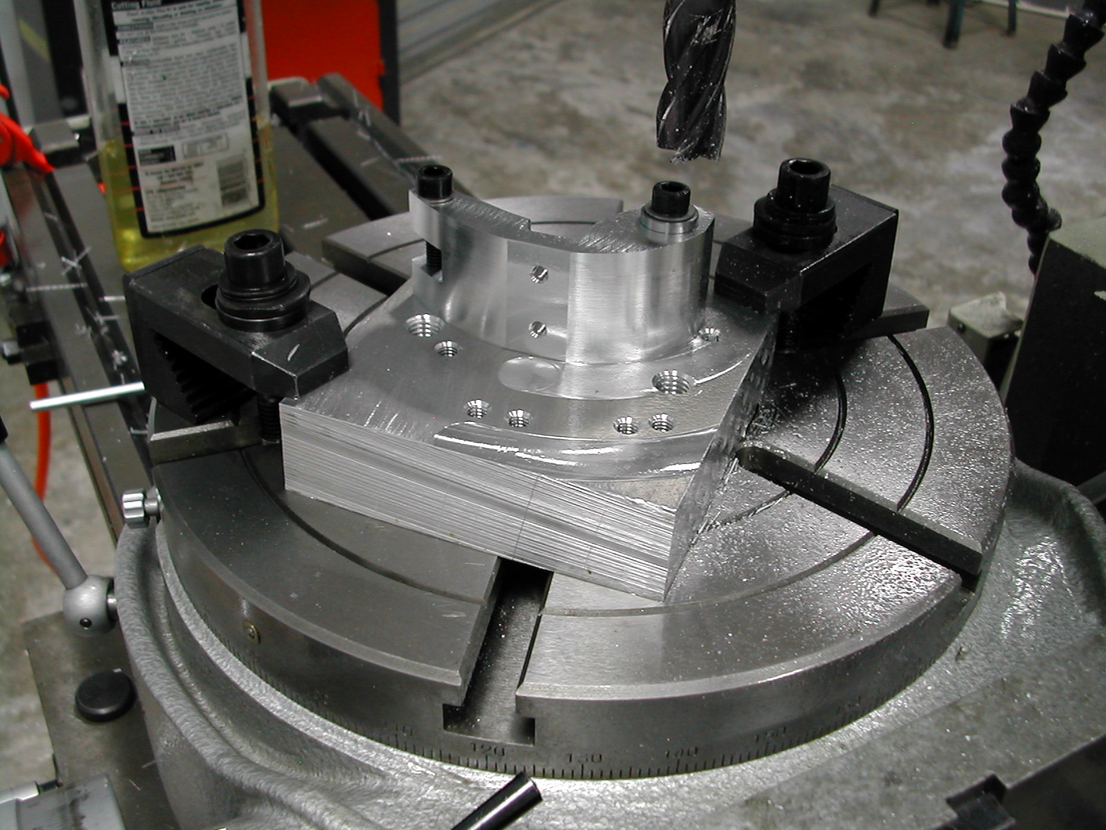
 The first cut is finished. Set your depth to cut just above the fixture surface, not below like I did. The small amount of “flash” left on the part is easily removed with a file and by not cutting the fixture you retain a nice flat surface for subsequent cuts.
 Arc #2 – the magenta arc in the plan
- Set rotary table to 0°00′
- Mount frame with large end at hole #2 w/flanged bushing, small end at hole #5, offset to right
- Starting from right of part, Y at 0.00, move X axis to 35.00mm + 1/2 cutter dia + 0.1mm stock
- Rotate table CW until cutter clears large end of frame (appx 80°) (conventional cut)
- Move X axis to 35.00mm + 1/2 cutter dia and cut CCW back to 0° (finishing climb cut)
- Repeat 8-12 for all frames
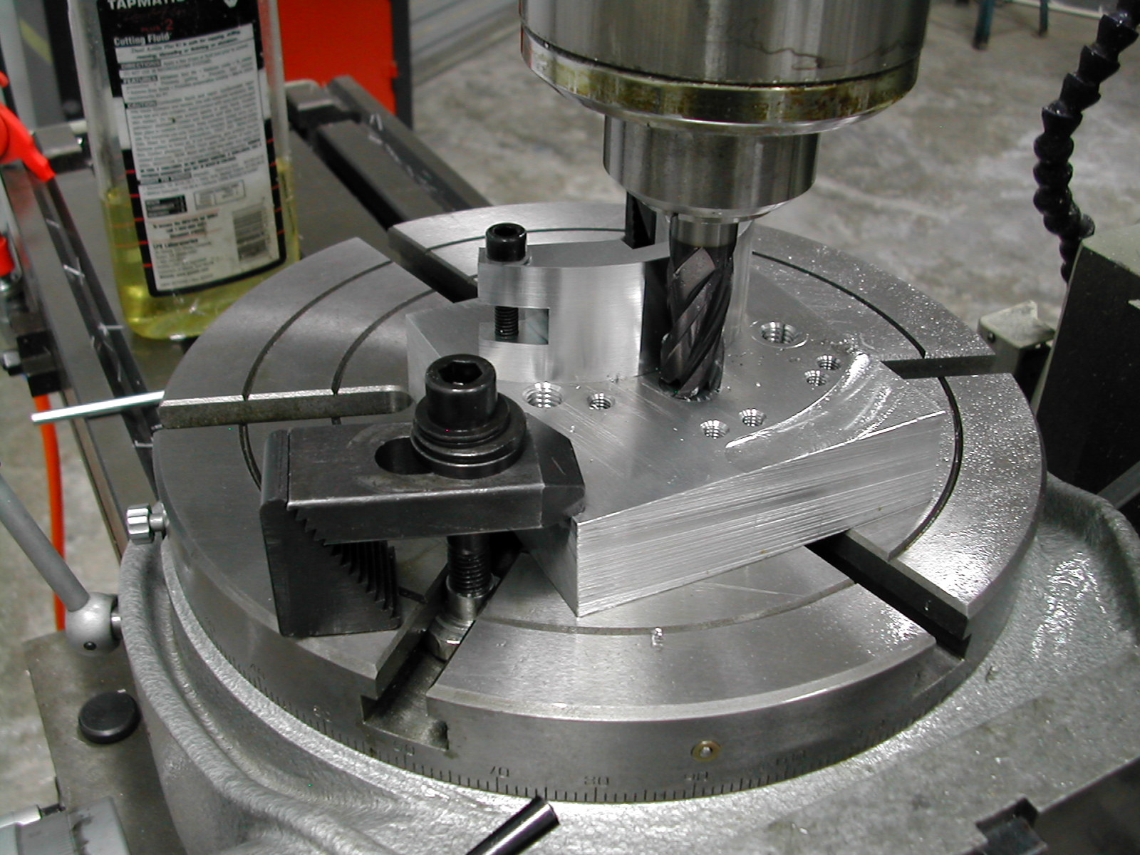
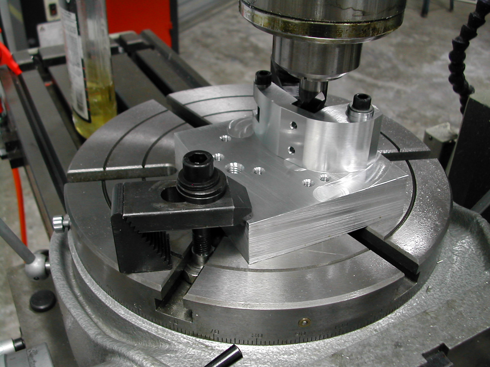
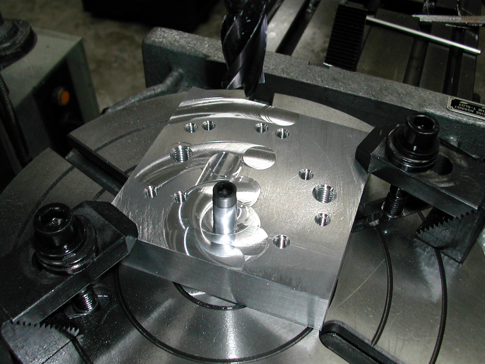
 This is the finish cutter position for arc #2, ready for unloading the part.
 Arc #3 (small end radius) – the yellow arc & straight cut in the plan
- Set rotary table to 0°00′
- Mount frame with large end at hole #9 w/flanged bushing, small end at hole #3, offset to bottom
- Starting above part, move X axis 33.00mm, feed Y axis to 5.00mm + 1/2 cutter dia + 0.1mm stock
- Feed X towards right to 0.00mm (conventional cut)
- Rotate table CW to 162°55′ (conventional cut)
- Move Y axis to 5.00mm + 1/2 cutter dia and cut CCW back to 0° (finishing climb cut)
- Feed X towards left back to 33.00mm (finishing climb cut)
- Back off Y above part
- Repeat 14-21 for all frames
 Arc #4 – the red arc in the plan
- Set rotary table to 0°00′
- Mount frame with large end at hole #4 w/flanged bushing, small end at hole #1, offset to right
- Starting from left of part, Y at 0.00, move X axis to 15.00mm – 1/2 cutter dia – 0.1mm stock
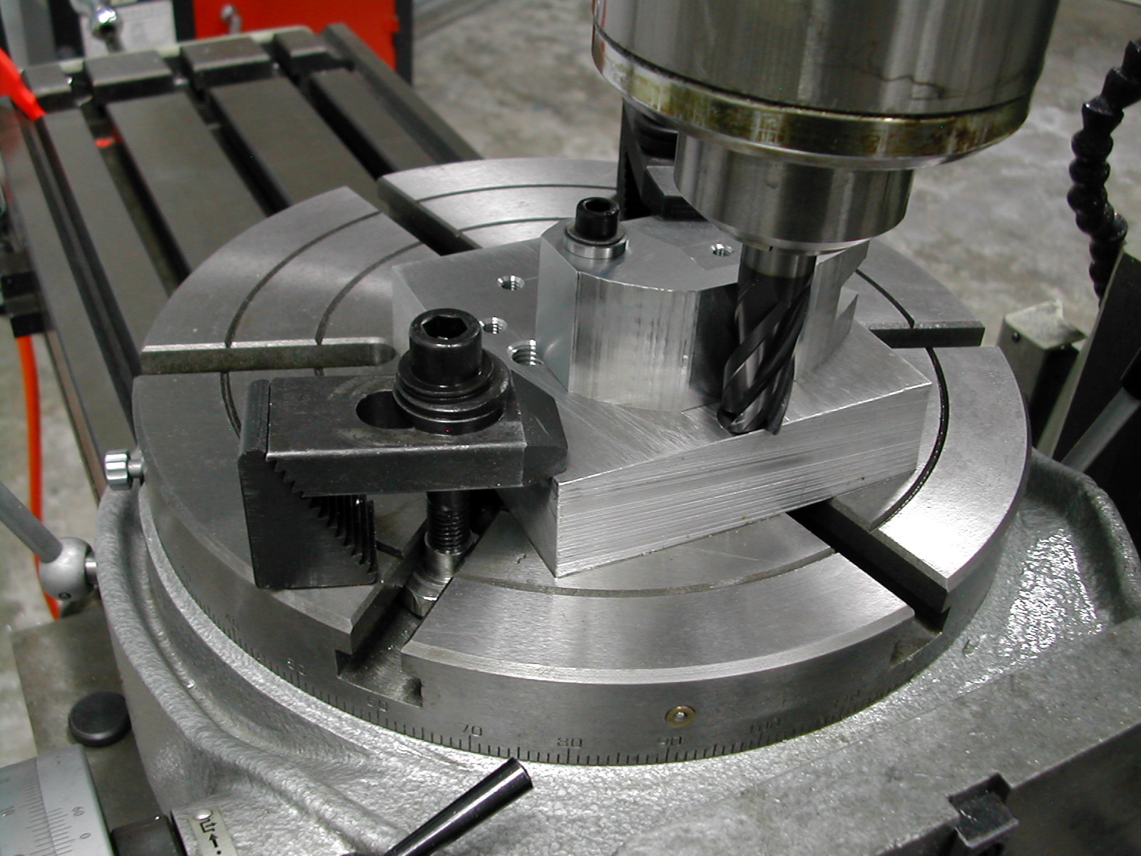
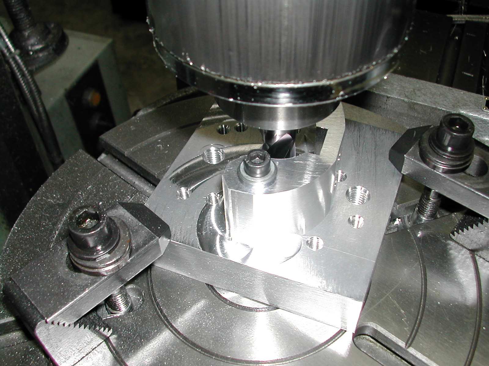
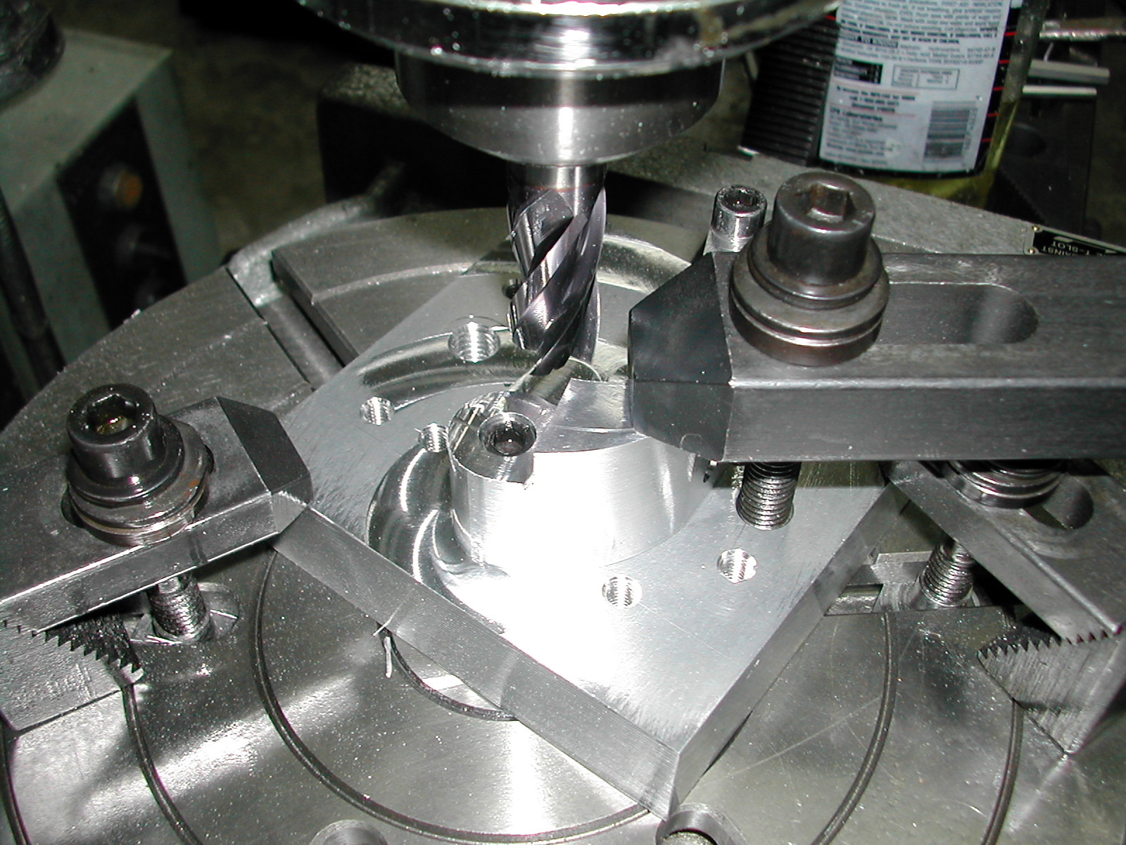
Since this a concave cut, I found it easier to plunge the cutter to depth at this point and then finish the rotary cut.
 Arc #4 – continued
- Cut CCW until cutter clears part (appx 140°) (conventional cut)
- Move X axis to 15.00mm – 1/2 cutter dia and cut CW back to off part (finishing climb cut)
- Repeat 23-27 for all frames
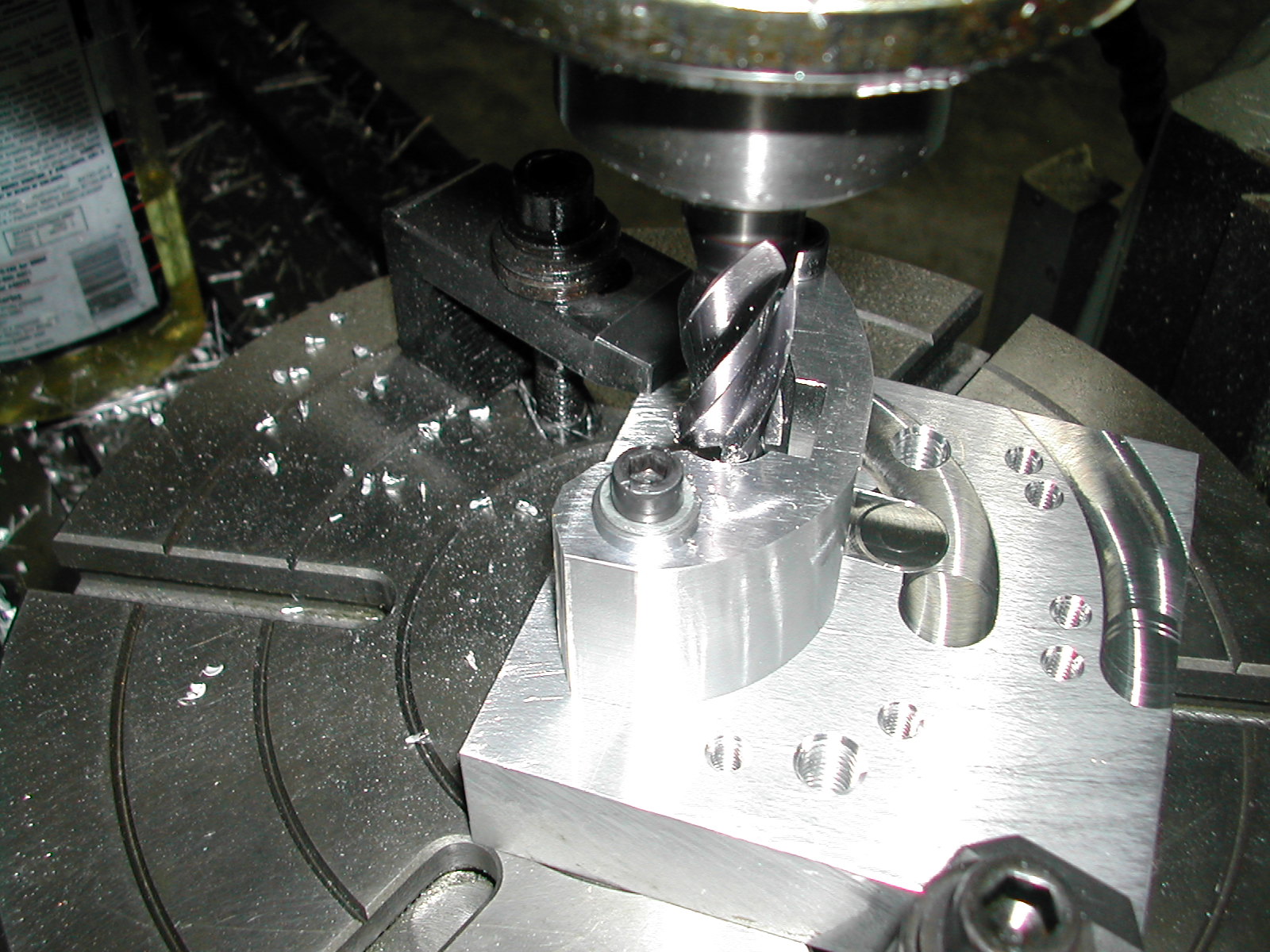
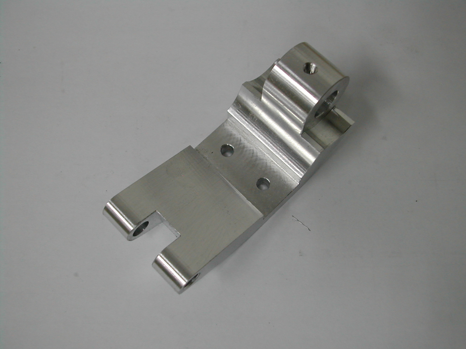
 Just one more end to shape.
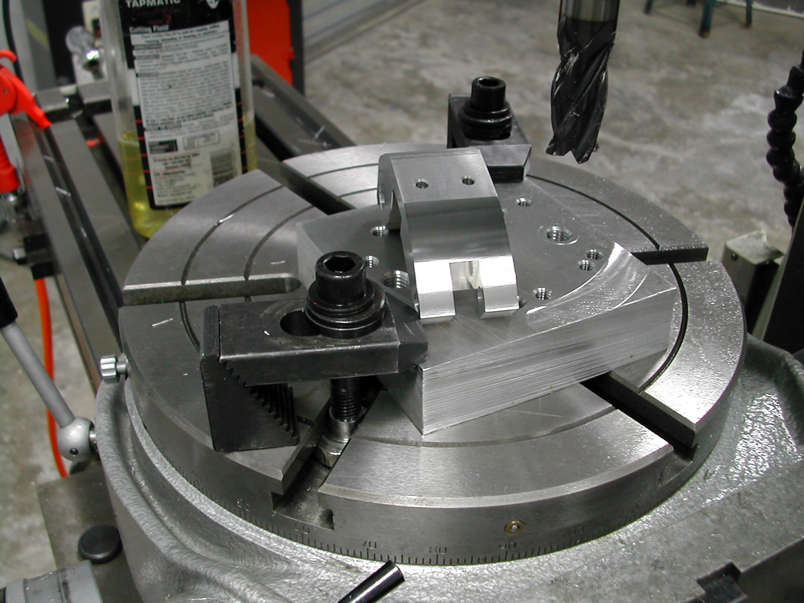
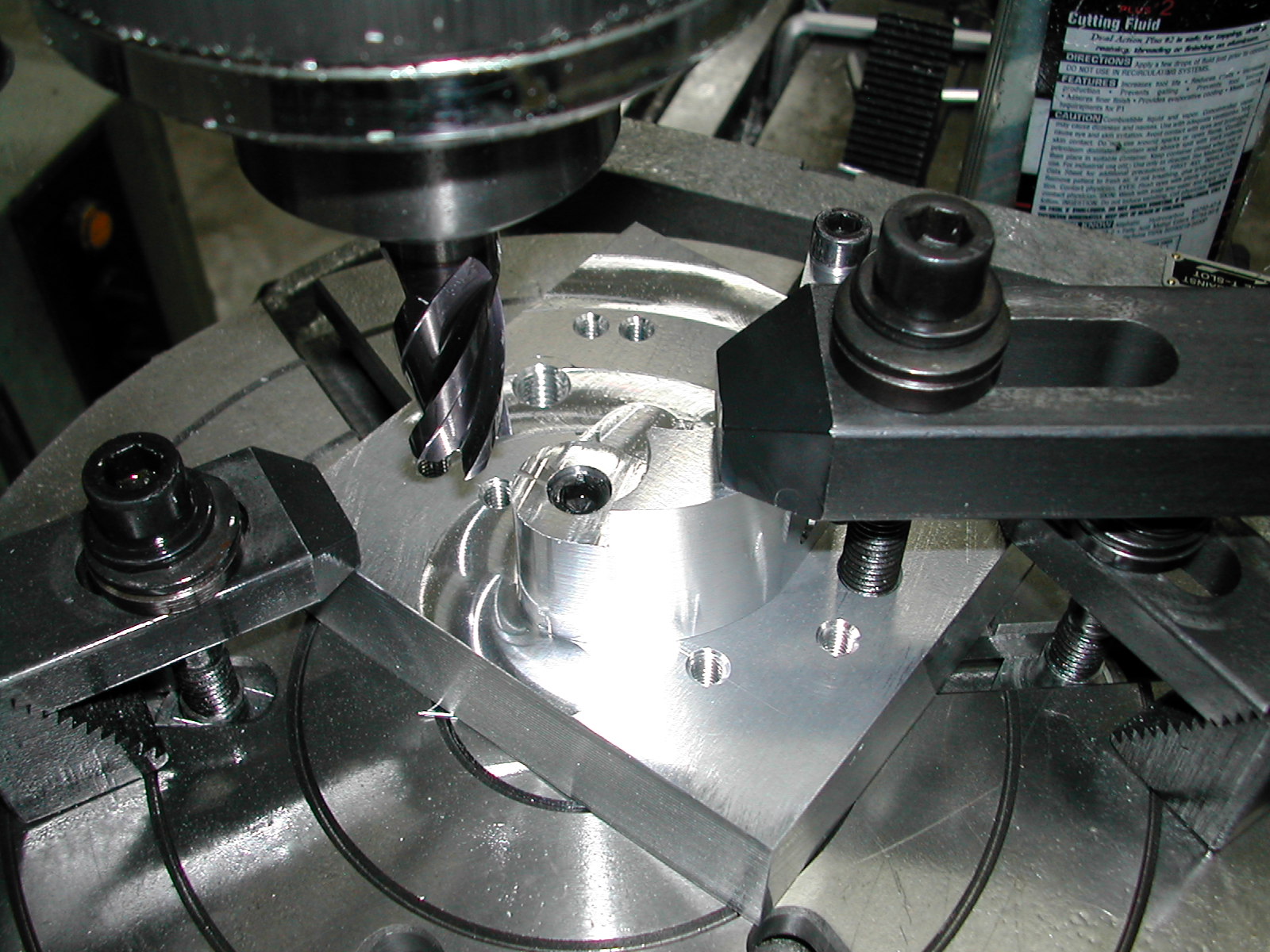
 Half of our parts are going to need clearance cuts for the hinge knuckles so we can’t use the headed bushing any more on the large end. Here I’ve mounted the short bushing.
 Arc #5 (big end radius) – the cyan arc in the plan
- Set rotary table to 0°00′
- Mount frame with large end at hole #3 w/short bushing, small end at hole #7, offset to bottom
- Add strap clamp at bottom
- Starting from right of part, Y at 0.00, move X axis to 10.00mm + 1/2 cutter dia + 0.1mm stock
- Cut CCW to 201°03′ (conventional cut)
- Move X axis to 10.00mm + 1/2 cutter dia and cut CW back to 0°00′ (finishing climb cut)
- Back off X to the left
- Repeat 29-35 for all frames
 Left Cheek Cut
- Set rotary table to 17°10′ CW
- Mount frame with large end at hole #3 w/short bushing, small end at hole #7, offset to bottom
- Add strap clamp at bottom
- With Y above part, Set Z (quill stop) to 8.00mm below top surface of part (do not move until done with all right and left cheek cuts)
- Traverse X back and forth across part moving Y to 7.00mm – 1/2 cutter dia below center
 Left Cheek Cut – continued
- With Y above part, move X to 10.50mm – 1/2 cutter dia – 0.1mm stock to the right of center
- Feed Y to 0.00
- Using quill to nibble small amounts, rotate table CCW to cut radius (appx. 120°) (conventional cut)
- Lock quill in down position, move X to 10.50mm – 1/2 cutter dia, rotate table CW to finish radius (finishing climb cut)
- Repeat 37-45 for 1/2 of frames
 Right Cheek Cut
- Set rotary table to 17°10′ CCW
- Mount frame with large end at hole #3 w/short bushing, small end at hole #8, offset to top
- Add strap clamp at top
- With Y below part, lock quill in down position (8.00mm below top surface of part)
- Traverse X back and forth across part moving Y to 7.00mm – 1/2 cutter dia above center
- With Y below part, move X to 10.50mm – 1/2 cutter dia – 0.1mm stock to the left of center
- Feed Y to 0.00
- Using quill to nibble small amounts, rotate table CW to cut radius (appx. 120°) (conventional cut)
- Lock quill in down position, move X to 10.50mm – 1/2 cutter dia, and rotate table CCW to finish radius (finishing climb cut)
- Repeat 47-55 for frames cut above
 With all the rotary table work finished, re-mount the vise and indicate it in. Working with the half of the parts that did not receive the cheek cuts, rest the flat bottom of one of the hone frames on the bottom of the vise and center the table on the width of the part. With a 14mm endmill, rough out the clearance for the center knuckle.
Using the same procedure we used on the pivot slots, open up the knuckle slot until the half with the cheek cuts moves freely in the slot with the axle inserted.
Next post: checking fit
All material, including the CAD drawings, relating to the construction of the External Hone presented on this site is free to use any way you see fit. However, no guarantees are made regarding the accuracy or correctness of the material presented here.
CAD Files Used On This Page (AutoCAD 2010 Format)
- All CAD files (4.6M .zip)
- Rotary table process plan (4K .txt)
- Engraving division degrees (24K .xls)