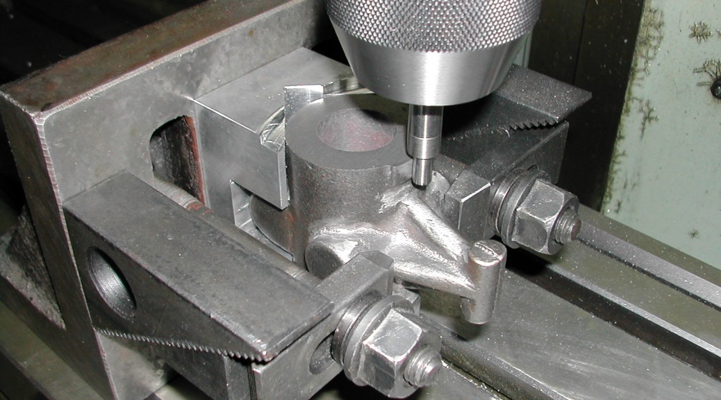
- Quorn Part 200, Wheelhead Collar
 Once again I had a casting that, based on my measurements and CAD models, wasn’t going to clean up completely. There are two pads on the wheelhead collar that get a 1″ radius clearing cut.
Measurements of my casting showed that the rough pads were at a 0.985″ radius on one end, while the other was near a 0.935″ radius. There was a little casting mismatch so I figured I would need an additional 0.015″ to clean these pads up.
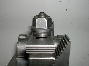
In the photo to the left, you can see that the pad on the right is significantly lower that the left pad. Unfortunately, neither has sufficient material to clean up at 2″ diameter.
In the end, I decided to offset the 1-¼” bore 0.050″ towards the back. The offset with the outside of the collar would be slight and somewhat hidden by the index ring on the top and the nut on the bottom. The remainder would be made up by reducing the diameter of the index ring to match the final clearing cut radius.
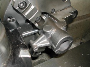 With that decided it was on to machining. I first attempted to mount the part in the lathe to bore the hole and face one end. However, the casting draft/shrinkage made securely clamping it in the 3-jaw chuck impossible without excessive force. I was worried that the part might work out during the initial interrupted boring cuts, or that the excessive clamping force would cause distortion in the finished bore.
If I threw the part out of the lathe, or ruined the bore, being in China meant obtaining a replacement casting would be tough and nowhere near timely. Therefore, I opted to run this initial boring operation in the mill.
I machined a V-block out of aluminum with a central groove to clear the clamping boss on the casting. This V-block will be used with an angle plate in the mill to hold the part vertically for machining. A tapped hole on the V-block made mounting and alignment on the angle plate easy. Since I was working with a casting, I just aligned the V-block vertically on the angle plate with a machinist’s square.
With the V-block mounted to the angle plate and the angle plate blocked up on the bench so the V-block was horizontal, it made it much easier to mount the casting with step clamps. Trying to do this vertically in the mill oftentimes requires four or five hands.
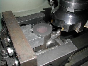 The angle plate was mounted to the mill table and aligned with a machinist’s square. Once again there really was no need to go through the trouble of indicating it square.
The face mill made quick work of knocking the end down. The webs for the adjustment screw bosses on my casting were about 0.320″ thick, so I used a caliper from the far side of one of these webs and the end of the casting and machined to a dimension of 1.535″.
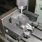 With the face milling done, I found the center of the outside of the casting since the cored hole was a little off. The Y direction was easy since the part was centered in the V-block. For X, I touched off the back of the part in the center of the “V” and moved in half the diameter minus the 0.050″ offset I determined earlier.
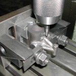 Just a quick check to see if the shortest pad is positioned where I though it would be. So far, the decision to offset the bore 0.050″ seems like the right one.
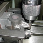 One last step before boring. I centered a gage pin over the adjusting screw bosses and recorded the distance to the center of the column bore. With my 0.050″ offset, this turned out to be 2.090″ for my casting. I’ll use this dimension to adjust the threaded adjusting screw hole locations in the wheelhead bracket to make sure the adjusting screws are centered over these bosses.
At this point, boring was rather straight forward. I used a small brake hone to take out the last 0.001″ to get a nice surface finish and a close sliding fit on the vertical column.
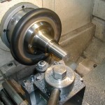 The next step was to machine a stub arbor in the lathe. One end was 1.000″ to fit a 5C collet and 1.250″ on the other for a nice sliding fit in the newly honed bore of the wheelhead collar, with a small shoulder to locate the collar’s milled face. I tapped the end 5/16″-24 for a bolt and washer to clamp the collar for the next machining operations.
While I had it in the lathe, I enlarged a little of the end of the 5/16″ hole and tapped it for a ¼” pipe plug. After I’m done with the arbor in the mill on this part, I’ll split the end and use it for an expanding collet to turn the OD and face both sides of the index ring and nut.
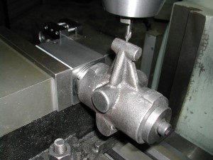 With the arbor securely mounted in a square 5C collet block, and the block clamped in the mill against a vise stop, I indicated the center of the arbor and stepped off 1.375″ from the shoulder.
To mount the collar to the arbor, I’m turning the collar until a center mounted in the chuck lines up with the centerline of the adjusting screw boss. Once I have that lined up, I tighten down the clamp screw locking the collar in place.
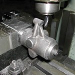 With the adjusting screw boss still vertical, I use an end mill to cut both ends to the 0.750″ dimension.
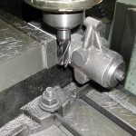 Without changing the part’s orientation, I mill the two pivot bosses to the 2.000″ dimension.
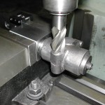 I rotate the square 5C holder in the vise to the next side. Here I can spotface the split cotter boss to clean it up, and then flip the 5C block 180° to do the other side.
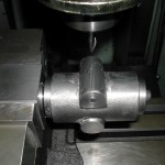 Flipping the collet block one more time to put the clamp boss up, I profiled the boss to match the split cotters. You can see by the amount taken off the boss, and the center of the spotface, I was pretty close with my 1.535″ centering dimension when milling and I probably should have only offset the bore 0.040″ instead of the 0.050″ I chose.
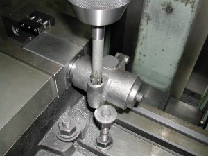 With all the milling operations complete, I switched to the drill chuck, flipped the 5C block once more and drilled and reamed the split cotter hole.
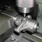 The last mill operation was to chuck a center drill and drill the two pivot holes. The use of the 5C block and the vise stop should insure that they are directly opposite each other.
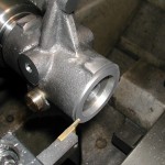 Here, I’ve taken the arbor back to the lathe, and mounted a tool that will allow me to make the remaining cuts without changing it, and I’ve verified that it can reach all three machining areas. Before mounting the part, I took a skim cut on the arbor shoulder with this tool and recorded the carriage location. Now I should be able to just back the carriage up 2-¾” and cut the part to length.
While I’m making the facing cuts to set the overall length at 2.750″, I stopped at one point to record the cross-slide reading and measure the diameter of my cut. I’ll use this so I can tell what diameter the pads clean up later since there’s no way to directly measure them.
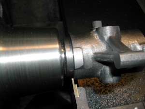 The last step is to make the clearing cuts. The shorter pad cleaned up at a 0.950″ radius. That will be the value I’ll use for the OD of the index ring, and the remaining pad.
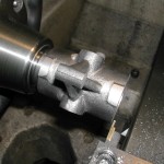 Here are both pads cleaned up at the 1.900″ diameter.
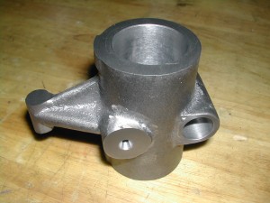 The finished wheelhead collar.
Disclaimer and License
All material, including the CAD drawings, relating to the construction of the Quorn presented on this site is free to use any way you see fit. However, no guarantees are made regarding the accuracy or correctness of the material presented here.
CAD Files Used On This Page (AutoCAD 2008 Format)
- 200 Wheelhead Collar (in Wheelhead archive) (8.1M .zip)
- 200 Wheelhead Collar as-built (233K .zip)

