
- Quorn Parts 100/101, The Bases
- Quorn Parts 102/103, Bed Bars
- Quorn Part 104, Wheelhead Column
 When dealing with castings, you have to remember that shrinkage, pattern mismatch, mis-located cores, and uneven surfaces can all contribute to making these parts hard to deal with. I was forewarned and ready to deal with the cored holes not being in the exact center of where the final holes needed to be, but when measuring the left base casting for my CAD model, I discovered that it was about 0.1″ short.
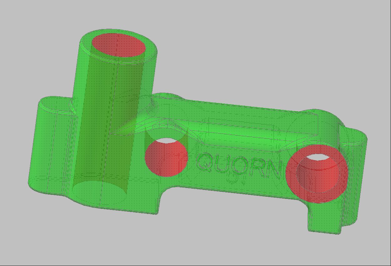 If I located the vertical wheelhead column centered in its boss, then the front bed bar location causes the micrometer base counterbore to not fully form.
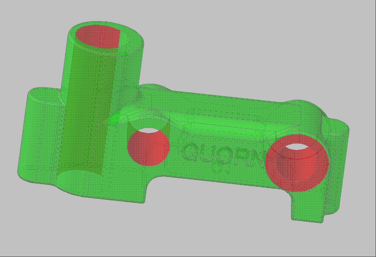 If I center the front bed bar to get a fully formed counterbore, then the vertical wheelhead post is visibly off-center and might not fully clean up.
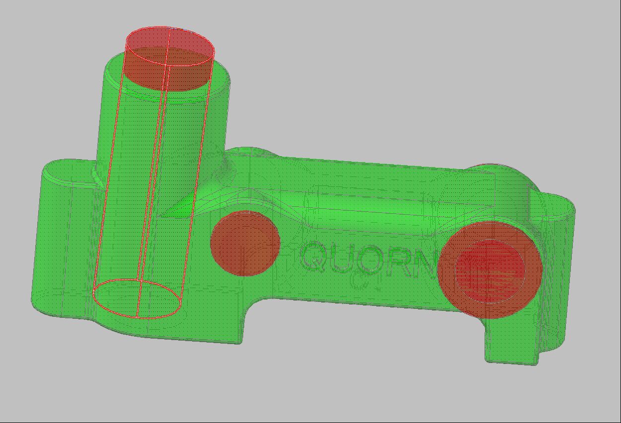 I started this last scenario knowing it was a long shot. Since the rear bar doesn’t have anything else around it to accentuate the concentricity of the bore with it’s boss, I wondered how much I would have to rotate the base around the front bed bar to move the top of the vertical column bore back into place (CAD is wonderful, but it sure can be a time waster). This left only the top half of the vertical bar bore cleaning up, and the rear bar way too close to the top of the casting. Once the base bottom was cut parallel with the bed bar bores, I just knew the now trapezoidal cutout on the bottom would look terrible.
 Splitting the difference, leaves me with both visual problems. I also considered for a short while just reducing the bed bar center-to-center distance from 3.5″ to 3.4″. This may have been the better choice, but I wasn’t sure of all of the ramifications this might cause having never actually used a Quorn.
Finally, I decided to go ahead and split the difference. When I’m painting the castings and “bringing forward” the surface, I can use a little Devcon to build up the area around the micrometer base if I need to.
Well, enough time wasted thinking — time to go and actually cut some metal.
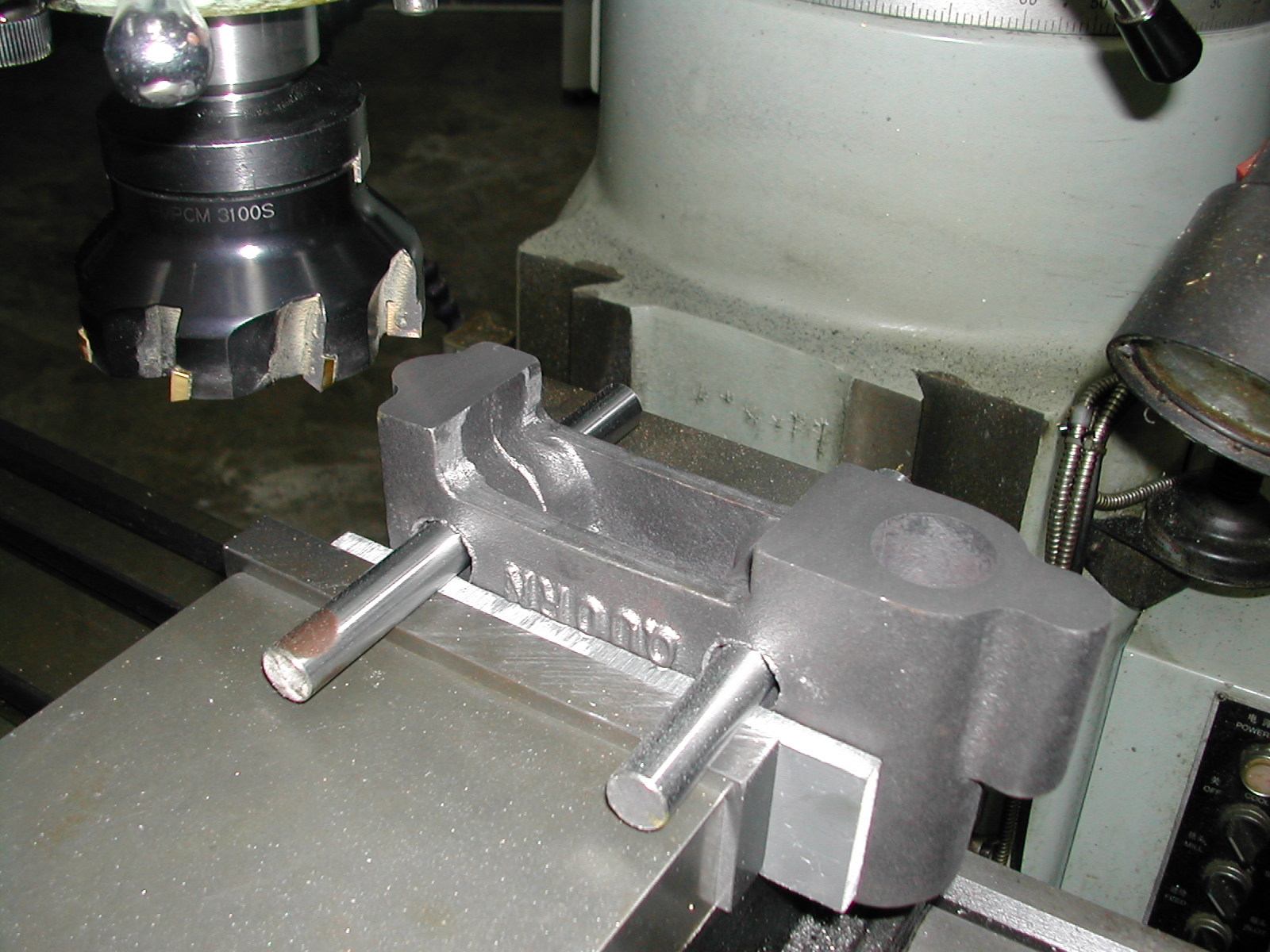
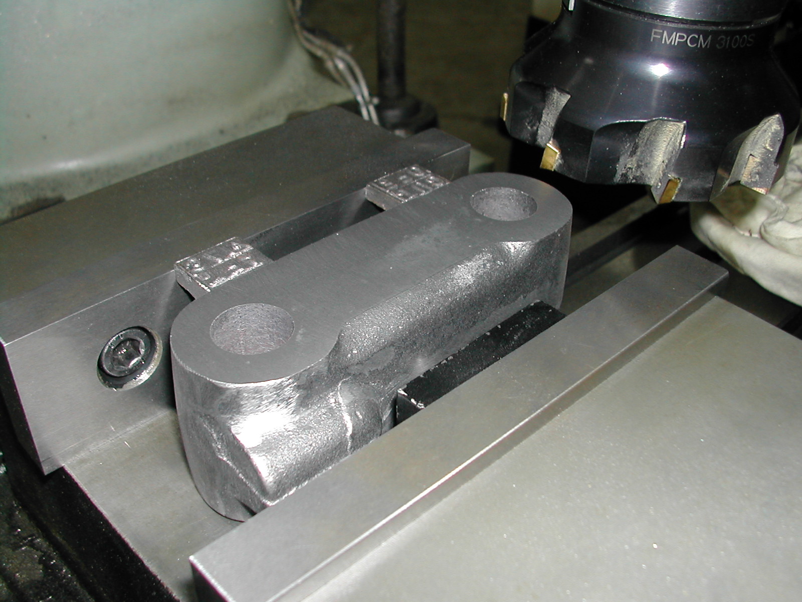
 From my CAD drawings and measurements, I knew the cored bed bar holes distances down from the base tops were fairly consistent. So I was able to insert some undersize round stock to locate the bases in the mill vise. Note the soft PVC stock between the part and the vise jaws. I wanted to make sure the casting was sitting on the cored holes and did not get kicked up when the vise was tightened.
 Here I’ve made a skim cut on the bottom. I cut this one a little heavier than I normally would have so I could be sure the right base would clean up at the same Z setting.
 This is the right base casting clamped up with the same round bars and milled without changing the knee height on the mill.
 With the base bottom now flat, it’s clamped securely against the fixed vise jaw and the face is roughly leveled.
 Here you can see I’m using a ball bearing between the moveable jaw and the part to insure the base is flat against the fixed jaw.
 This is the right base clamped up in the same manner to clean up its inside face.
 The carbide insert face mill does a great job on these cast iron castings.
 Now that the bottoms of the bases are flattened, and the inside faces have been flattened and squared to the bottoms, I’m clamping them together on top of the surface plate to check the cored hole alignment.
 I’m visually centering the front and rear outside bed bar bosses.
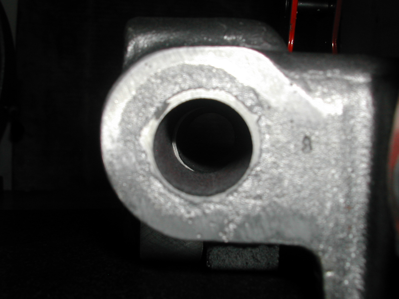 With the outside visually centered, you can now see the cored hole mismatch. I’ll have to go easy when starting the bores since the mismatch will create and interrupted cut when starting.
 Starting with a angle plate that has been indicated in square with the mill axis, I first mount the left base casting. Here I’m indicating the machined inside face level.
Once the left casting is anchored in the correct orientation, it’s a simple matter of laying the right base casting on top of it, aligning the outside bed bar bosses as before, and clamping it to the angle plate and the left base casting for good measure.
 With a temporary clamp in the front bed bar hole, I’m ready to begin boring the rear one.
 I’m using the shortest boring bar I can and it doesn’t leave a lot of clearance with the casting. Once both holes are bored, without removing them from the angle plate, or the mill, I lapped both holes to a close slip fit with an expanding brass lap.
With good reason, Chaddock recommends making the rear bed bar holes 0.003″ oversize so the Loctite will have the proper film thickness to bond. After all this exacting work making sure the bores were square, straight, and on-size, I just couldn’t give up this hard fought precision, so be sure to check out my bed bar and wheelhead column pages for my solution.
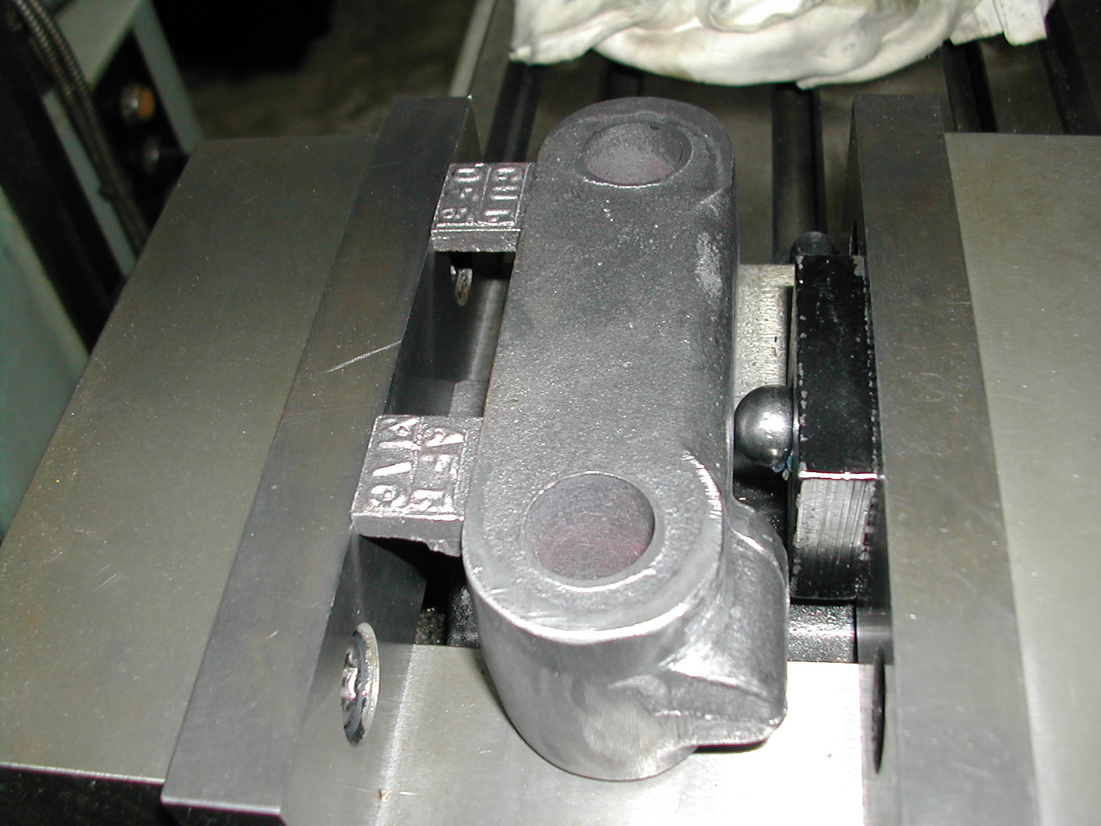
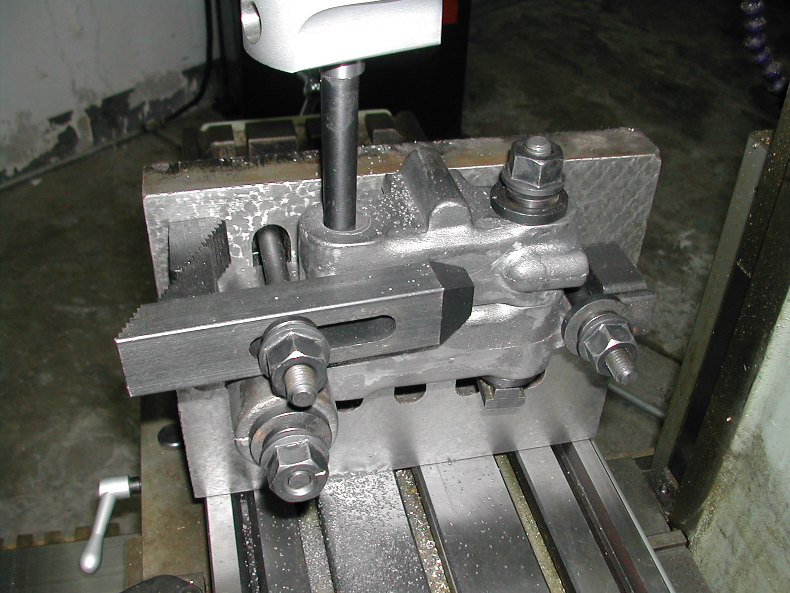
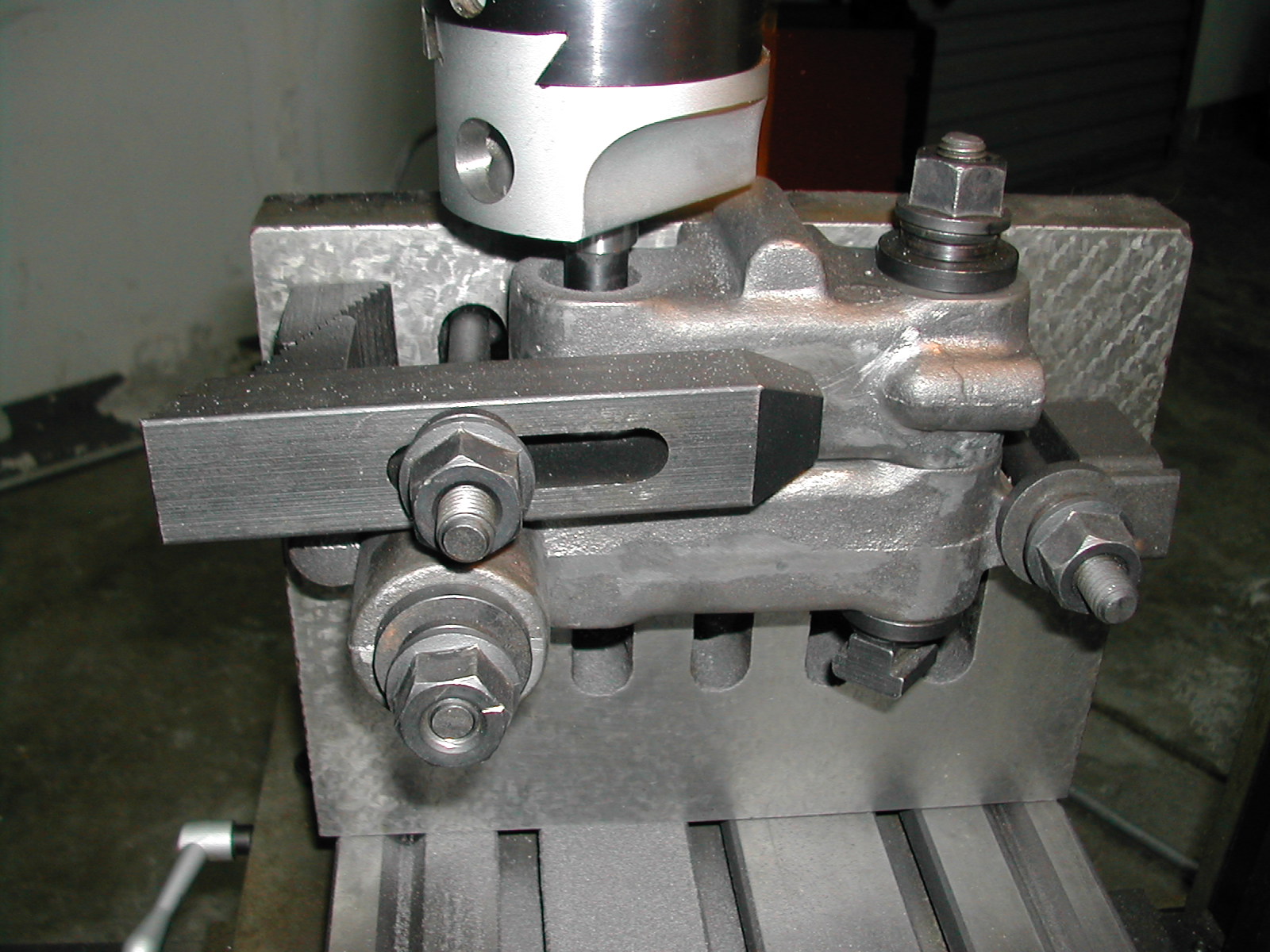
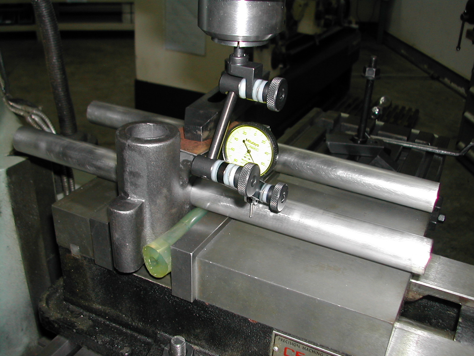
 Now, I’m using the actual bed bars in the left base to clamp it for boring the wheelhead column bore. You can see I’ve got a clamp forcing the base down on the bar which are resting on top of the vise jaws. The machined inside face is against the fixed jaw, and I’ve got a compliant urethane spacer between the irregular casting and the moveable jaw. Unless you have a precision ground vise, like a Kurt, you’ll probably want to use some 1-2-3 block for this instead of the vise jaws.
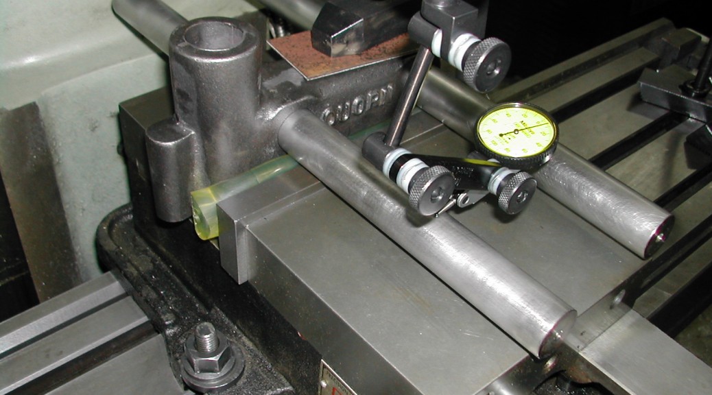
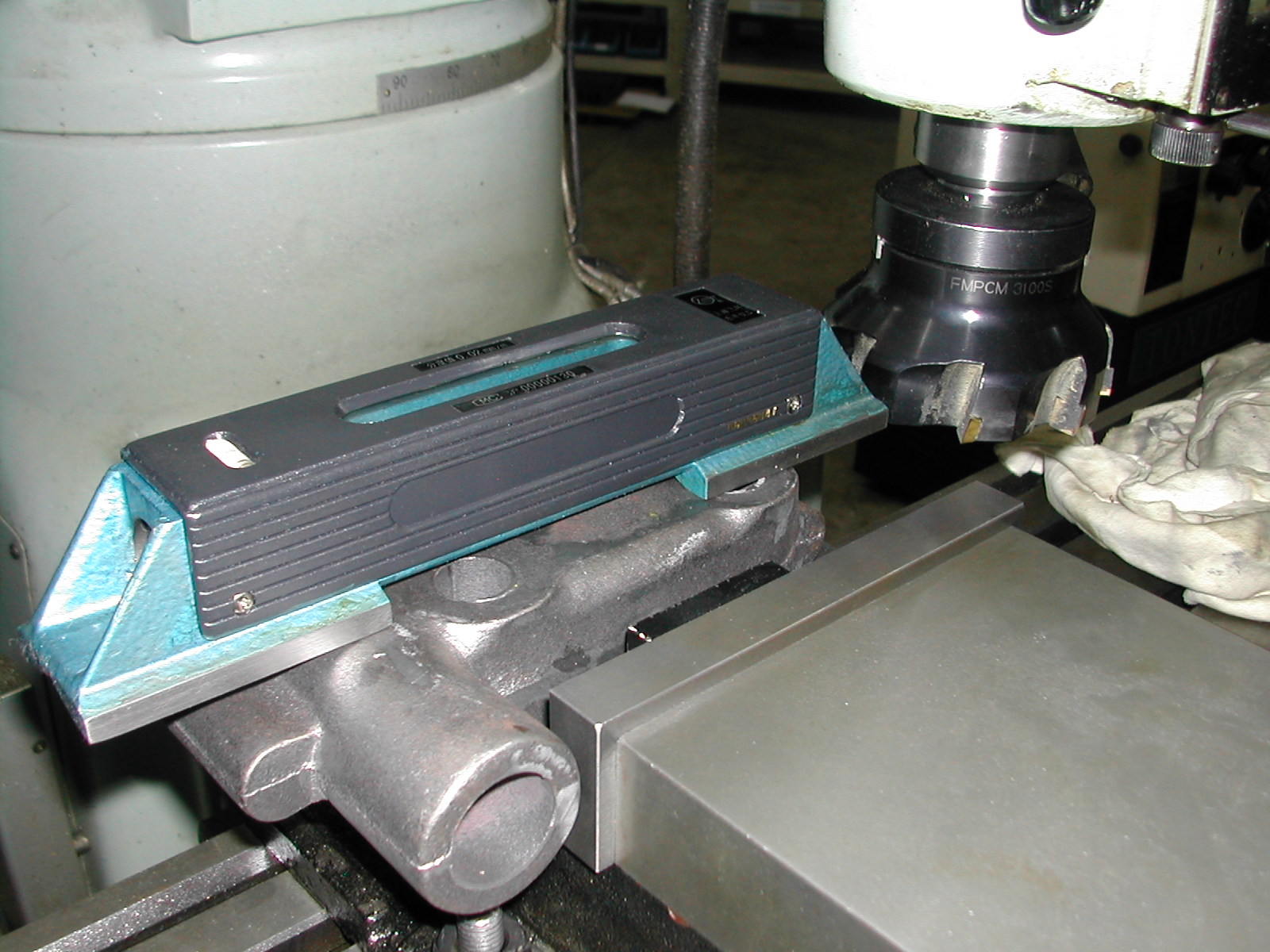
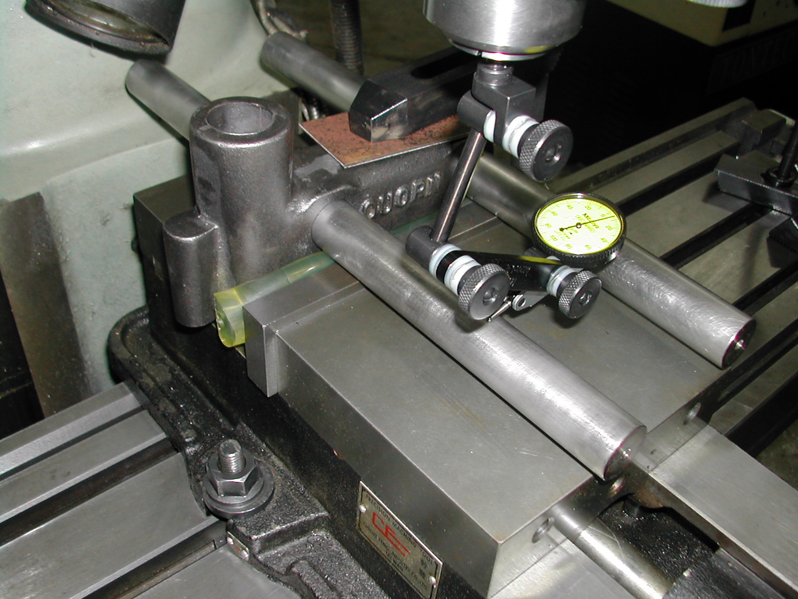
For peace of mind, I’m verifying the bed bars are level before proceeding.
 There’s a Russian proverb “doveryai, no proveryai”, which Ronald Reagan used to quote as “Trust, but Verify”. Even though the vise has been indicated in parallel with the table and the bores are supposed to be normal to the inside face of the base casting, I’m just checking to make sure the bed bars are indeed perpendicular.
 Now that I’m satisfied the casting is fixtured correctly, it’s time to actually locate the bore. Here I’m finding center on the rear bed bar. The wheelhead bore is supposed to be 1.375″ back from this.
 Once I’m back the correct distance from the rear bed bar, I’ll indicate the boss to locate the center in the other direction.
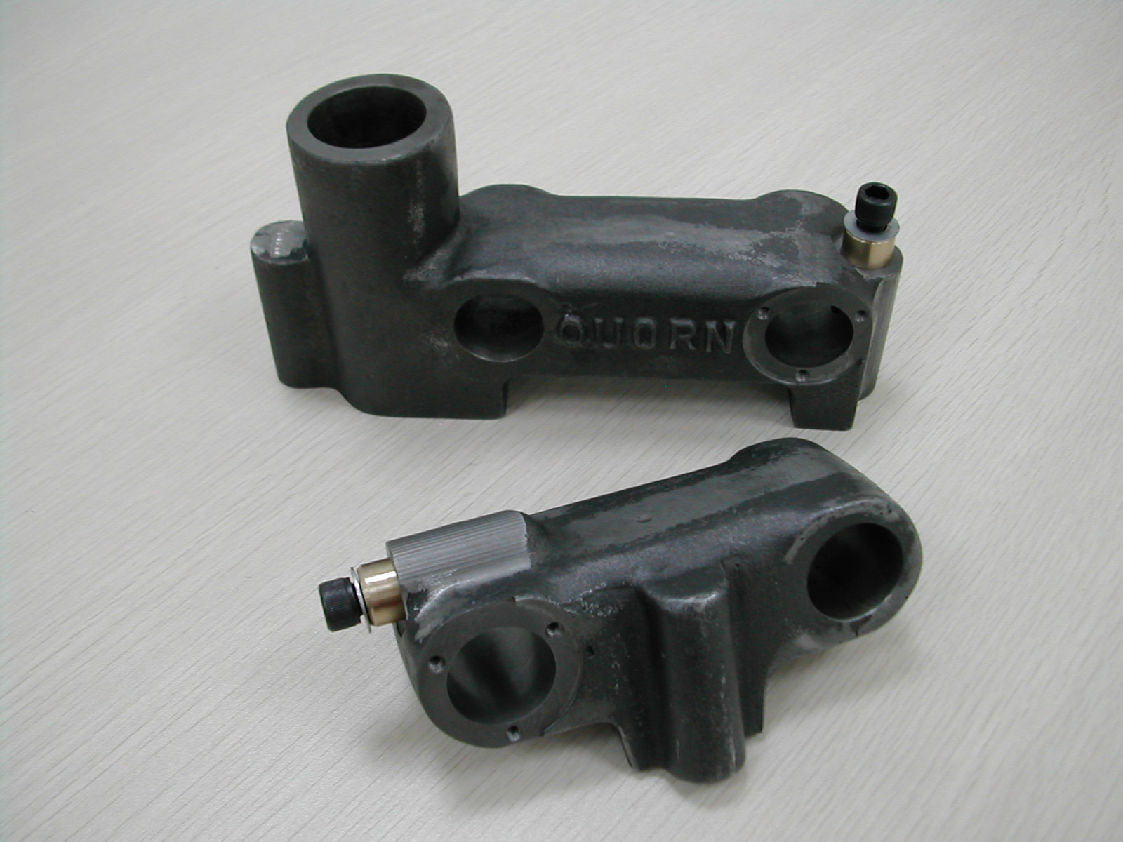
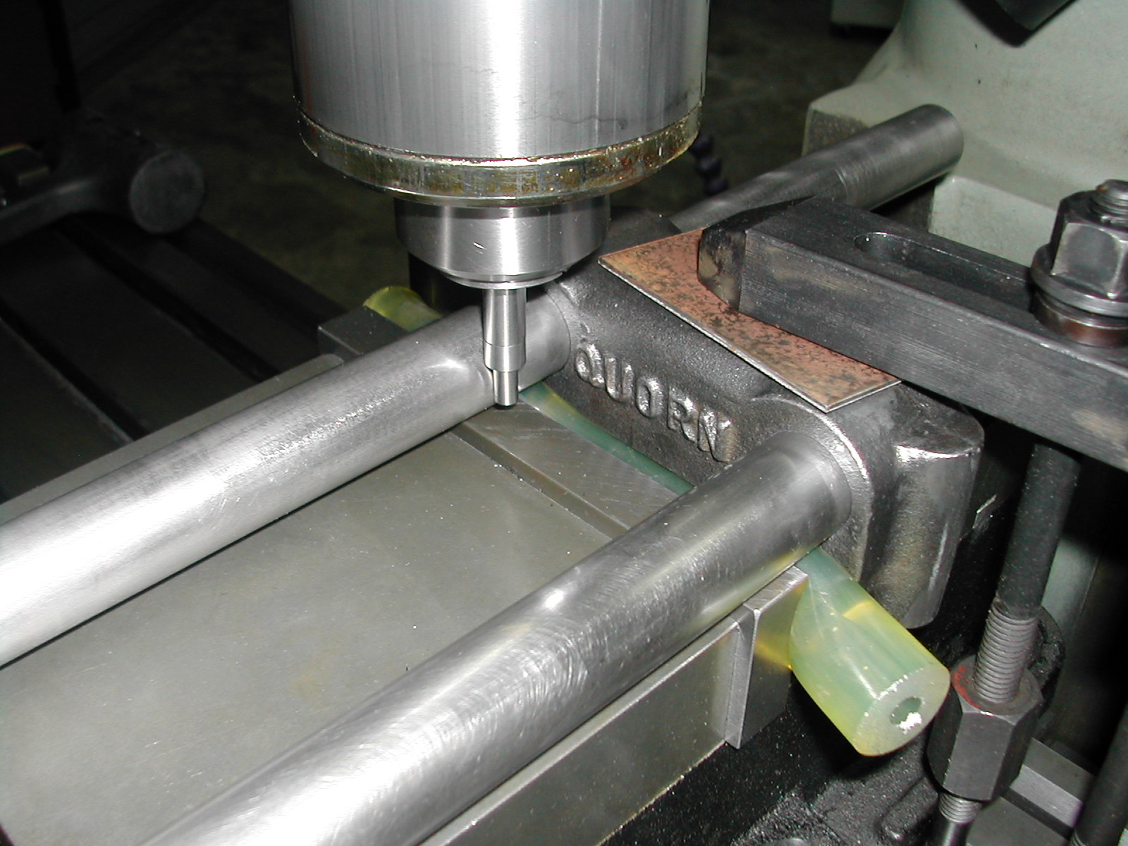
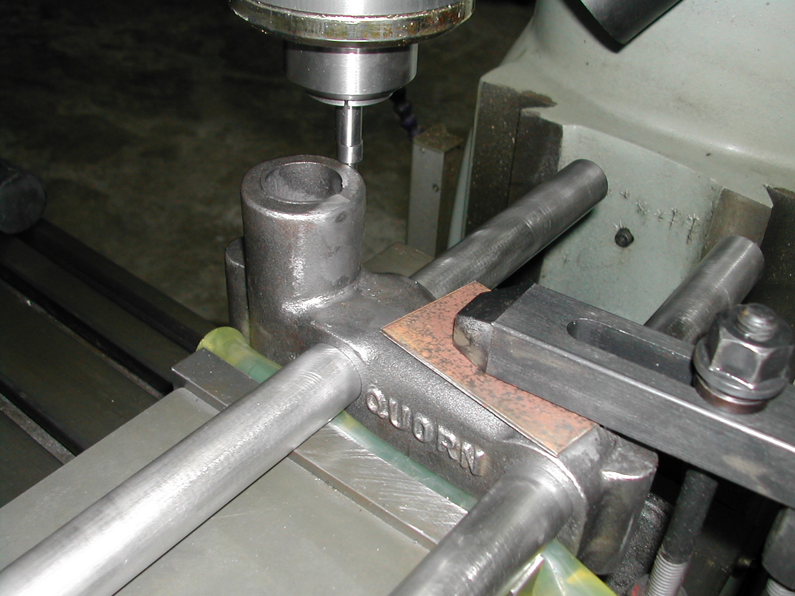
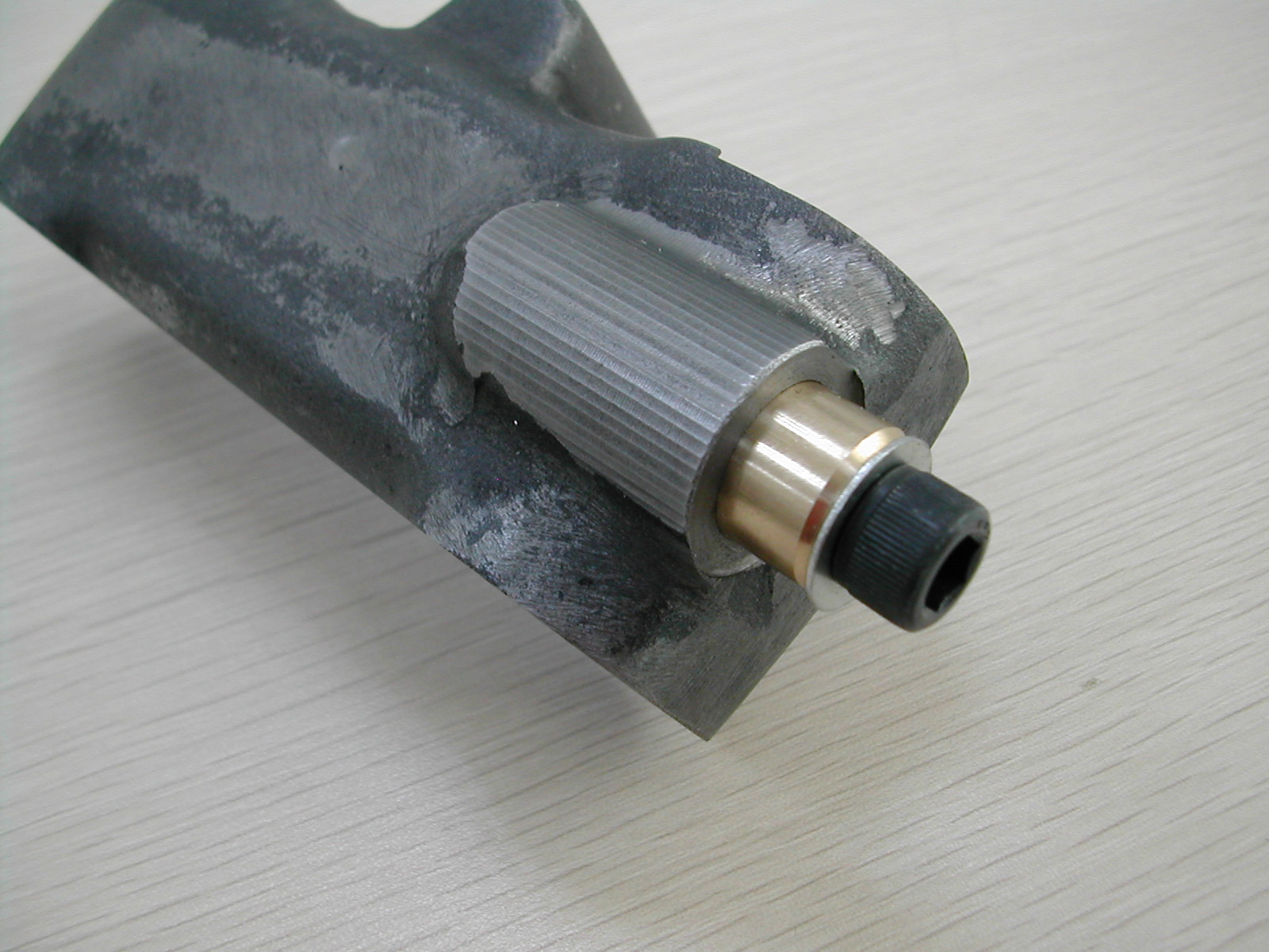
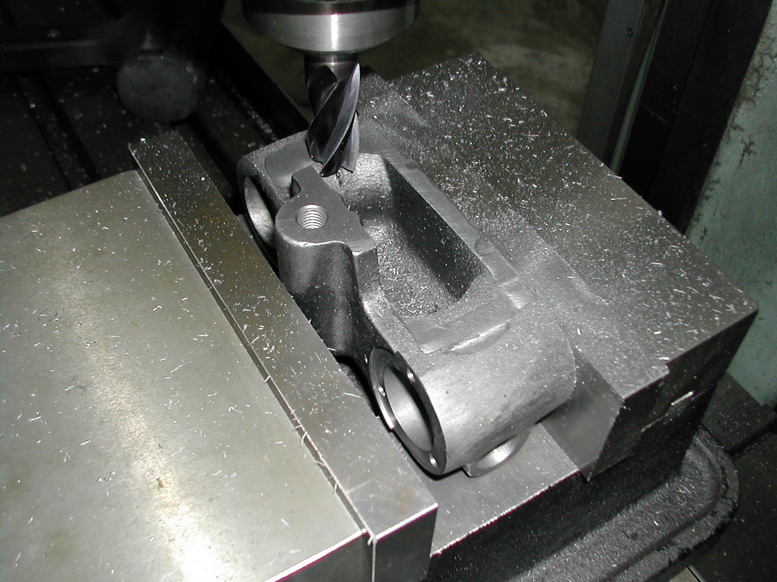
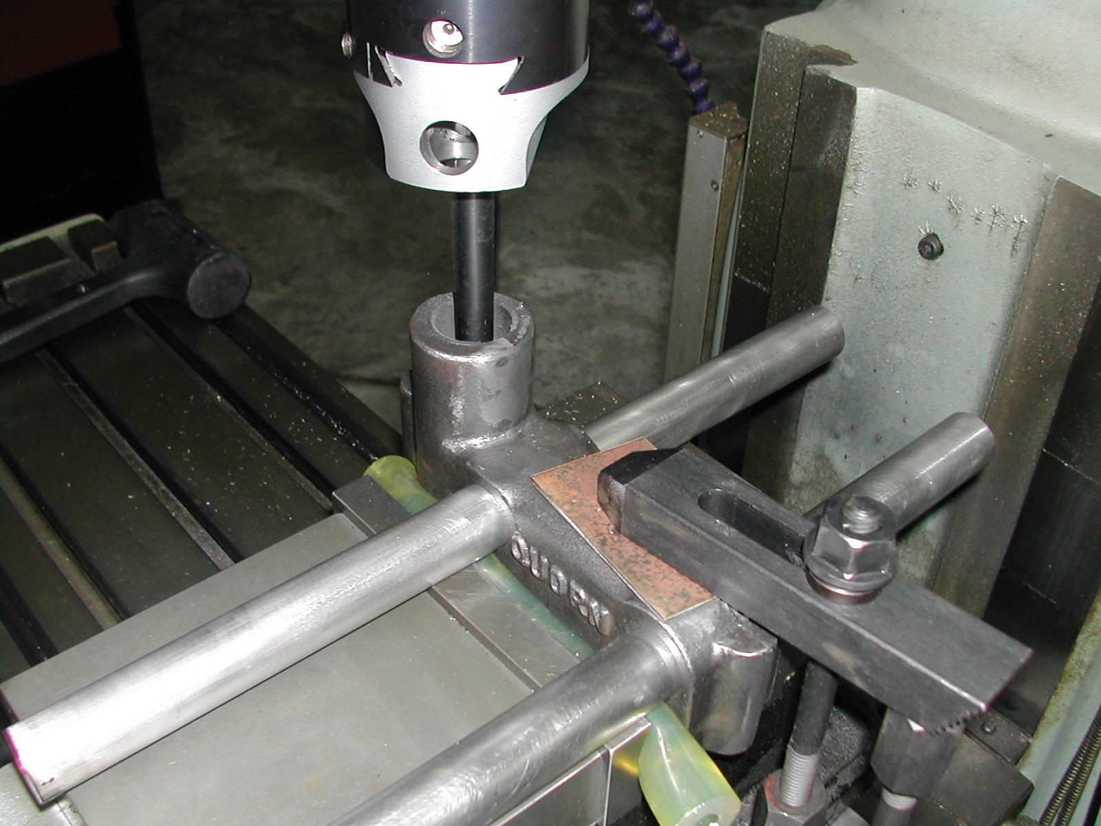 Here I’m boring the wheelhead bore to a slight press fit on the vertical bar. There’s no need to compromise accuracy at this point by boring oversize for the Loctite film since I’ve knurled the portion of the bar that gets inserted into the base.
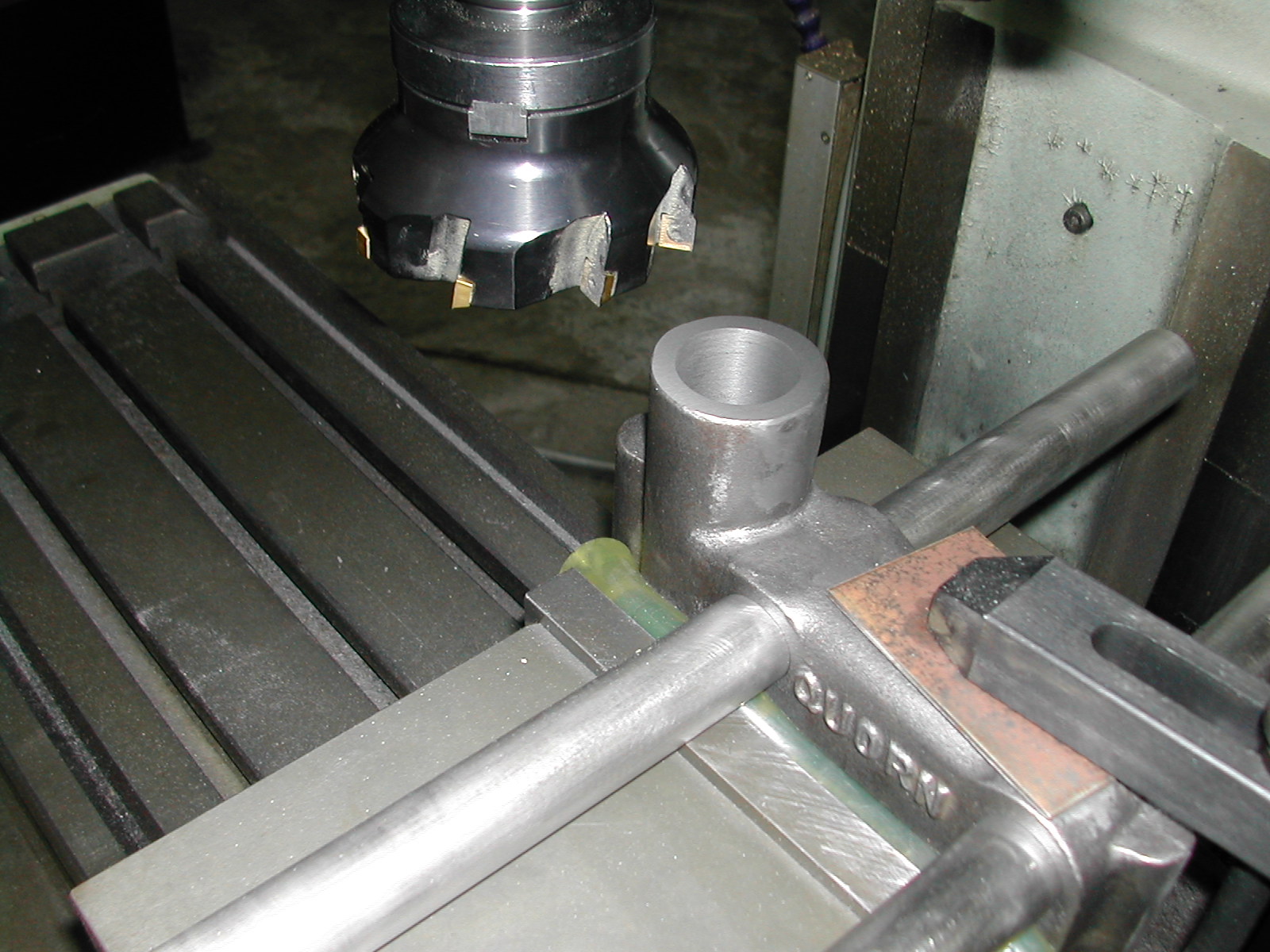 For looks, a quick swipe with the face mill to flatten and square up the top of the boss while it’s still clamped up and square.
 The next step on both castings was to install the cotter locks. These will be needed to fixture the parts for the remaining operations. Please see the cotter page for details.
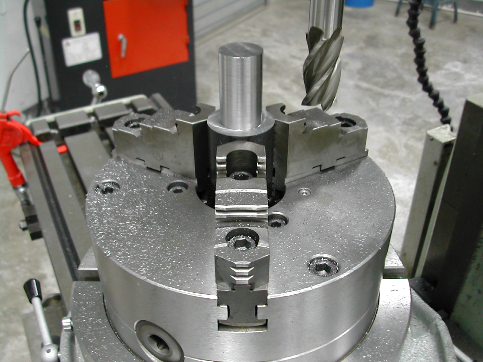 Here I’ve mounted the rotary table on the mill and machined a stub arbor in-situ to insure it’s concentric. This will be used in combination with the cotter locks to fixture the bases to spotface and tap for the dust covers, micrometer base, and spring cover.
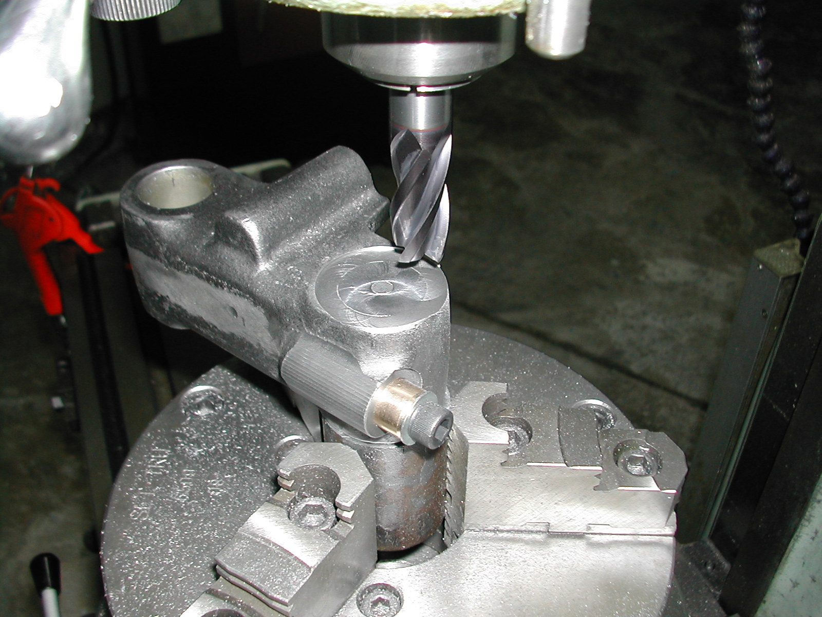 At this point orientation is not critical so I’ve just mounted one of the bases and tightened the cotter to hold it in place on the stub arbor. An end mill makes quick work of the spotface for the spring cover here on the right base. The spotface for the micrometer base was done similarly on the right base.
 With the milling finished, the end mill was replaced with a drill chuck to complete the #4-40 and #6-32 holes in the castings. To correctly orient the castings on the stub arbor, the rotary table was turned to zero and the cotter loosened. A pin was inserted in the chuck and the table was offset the 3.500″ center distance of the bed bar holes in X and the bed bar radius minus half the pin diameter in Y.
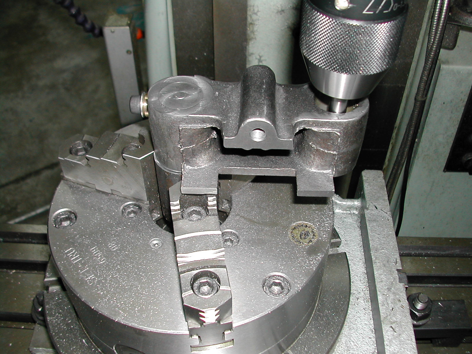
It was then a simple matter to swing the casting around to the pin and lock it in place with the cotter.
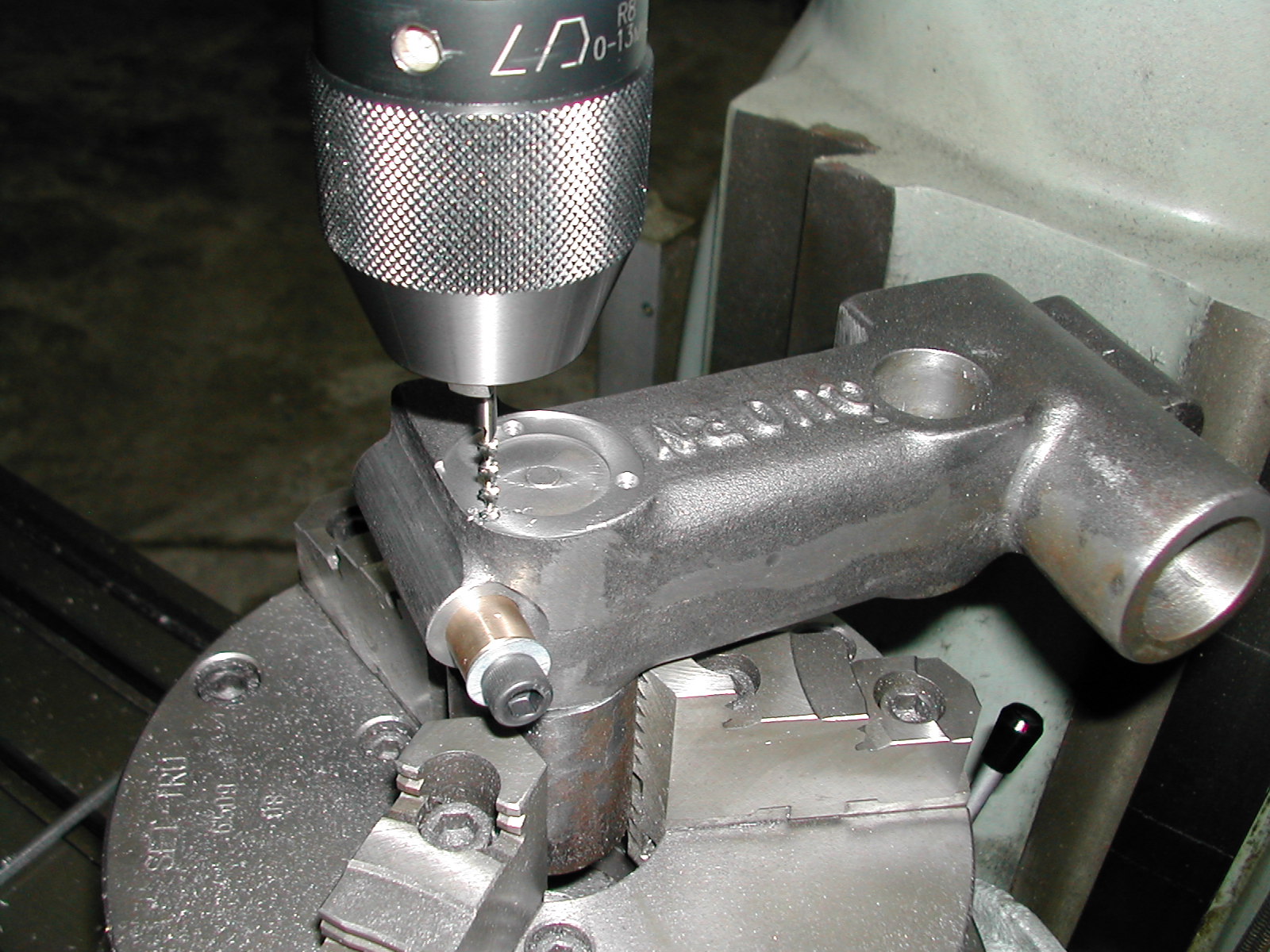 Here I’m tapping the #6-32 holes for the micrometer base on the left-hand base casting. I normally prefer to power-tap in the mill, but on these small diameter taps in blind holes, I put the mill’s transmission in neutral, and with a little pressure on the quill to offset the return spring, I hand-turn the chuck.
Most taps are broken because of side loading. By tapping in the mill using the chuck, I can get pure torsion on the tap without any side-loads. Not only is my tapped hole always concentric with the drilled hole, it is extremely rare that I break a tap.
 The same procedure was used for the #4-40 dust cover holes in both the base castings.
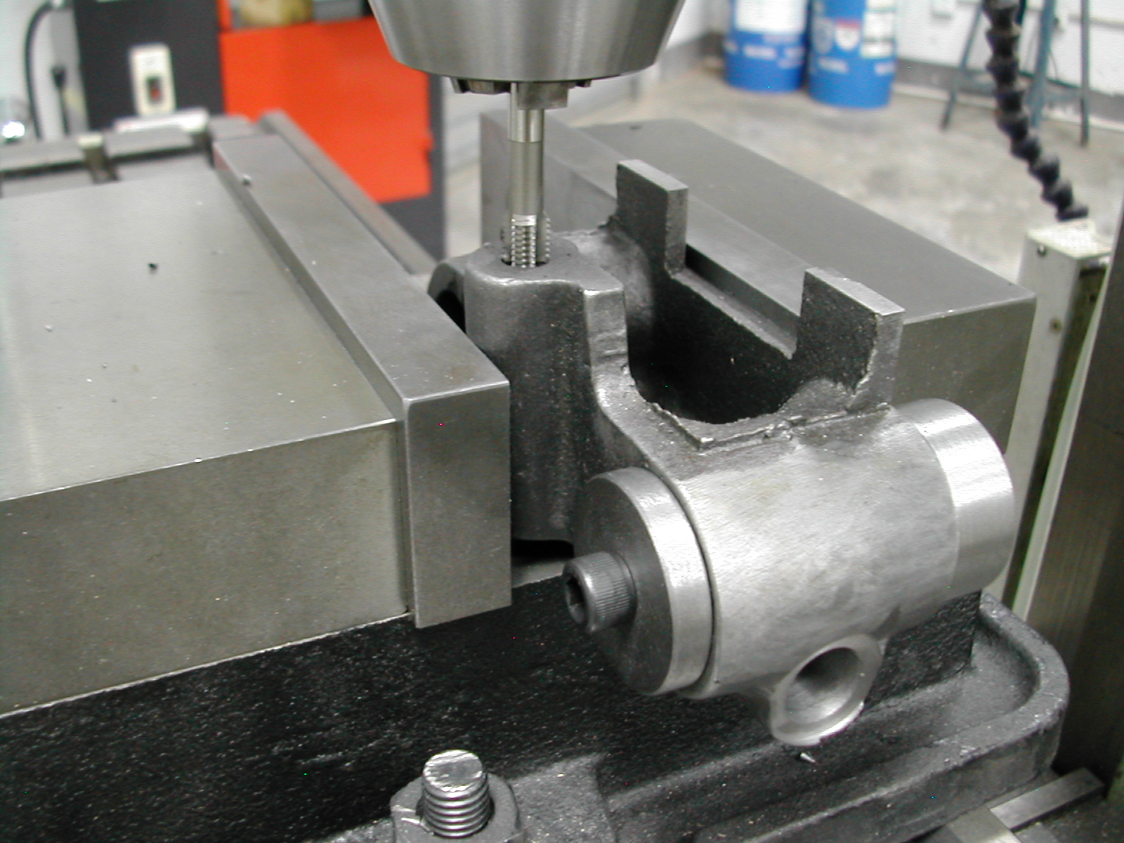 With the rotary table work finished, the vise was remounted and some power tapping was used to put 5/16-24 tapped holes in for the base leveling feet. I decided to tap the bosses instead of using through holes as per Chaddock because I think it gives the Quorn a cleaner look, and I’ll be able to use some niced knurled feet to level the finished cutter grinder.
Also, since I chose to put a split cotter in the left base to provide another locking point for the front bar (and a way to hold the casting for machining), there was no longer any way to put a through hole at that location.
 The last step is to remove the machining tabs from the right base.
This completes the machining operations on the base castings. These will now be set aside until it’s time to paint and assemble the finished quorn.
Disclaimer and License
All material, including the CAD drawings, relating to the construction of the Quorn presented on this site is free to use any way you see fit. However, no guarantees are made regarding the accuracy or correctness of the material presented here.
CAD Files Used On This Page (AutoCAD 2008 Format)