
- Hodgson Part 035, Crank Cheeks
- Hodgson Part 043, Impeller
- Understanding Crankshaft Counterweights
 The impeller started life as a 125mm diameter by 300mm piece of Aluminum 7075-T6. I bought a stick of this long enough to make the front cover, crankcase, rear seal plate, air guide, impeller, and a few fixtures. The diameter was needed to accommodate the crankcase so I did end up wasting a little material on the other parts.
 I’ve changed up the design on the rear crank by adding a stack of 0.001″ shims on both sides of the impeller. These will allow me to adjust the impeller-air guide clearance as well as the center-to-center distance of the distributor miter gears.
The rear crankshaft has been lengthened and a locknut added to hold both the impeller and distributor gear in place.
 I laid out the profile of the impeller in 043 Profile Drawing, and created a profile Excel spreadsheet to help me turn this on my manual lathe. I’m using a Korloy MGIUR4025-3 toolholder with a MGMN300-M insert to cut the profile.
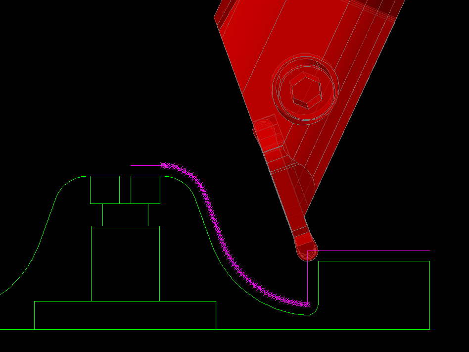
 To start, I’ve roughed out the profiled end of the impeller based on the roughing path I created in the CAD drawing.
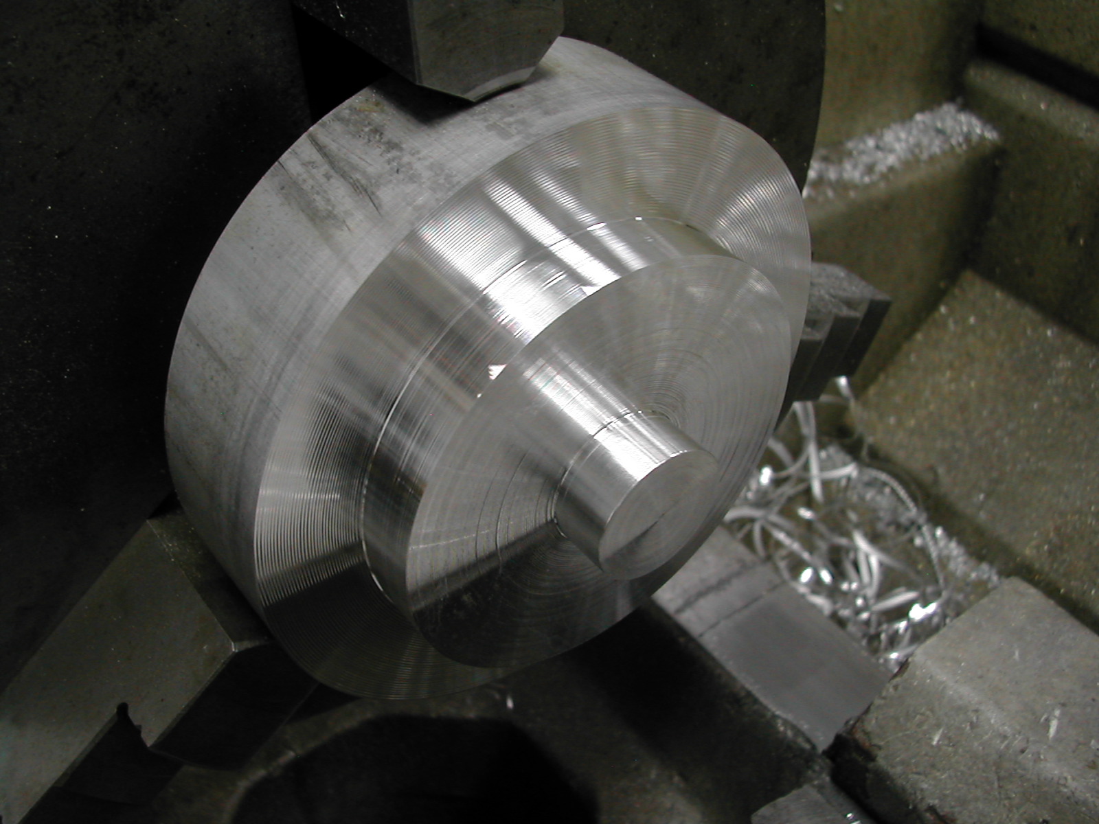 The next step was to rough out the O.D. to within 0.050″.
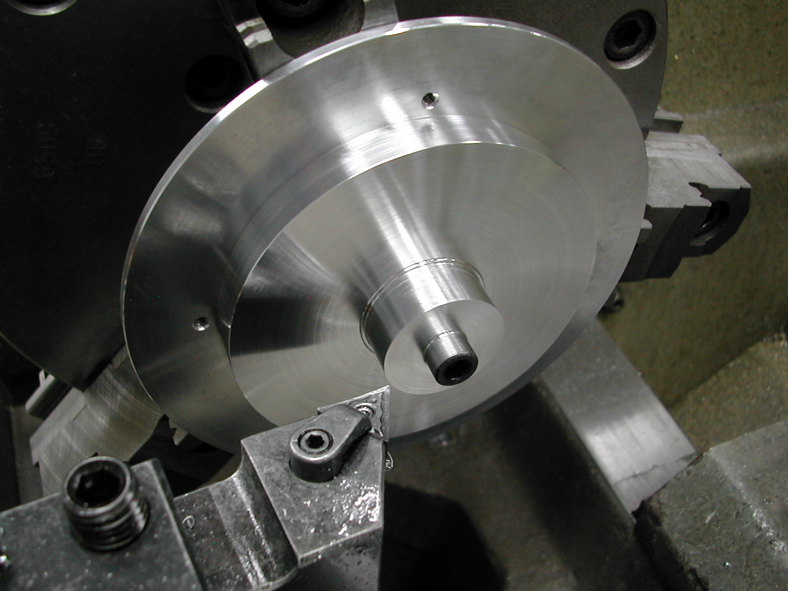
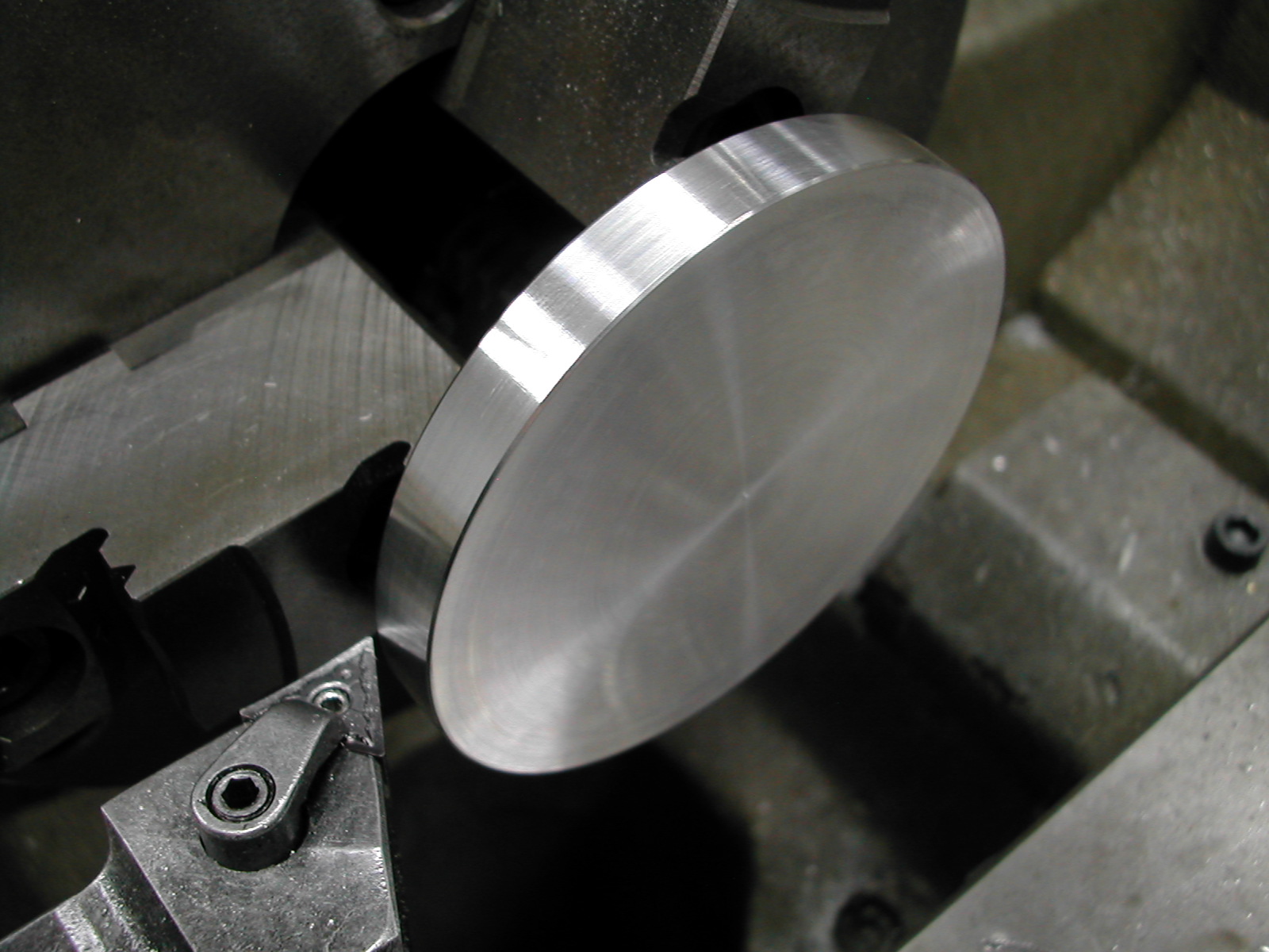 After sawing the roughed out blank from the stock, the blank was chucked up on the profile end and a minimal facing cut was taken and the final O.D. turned.
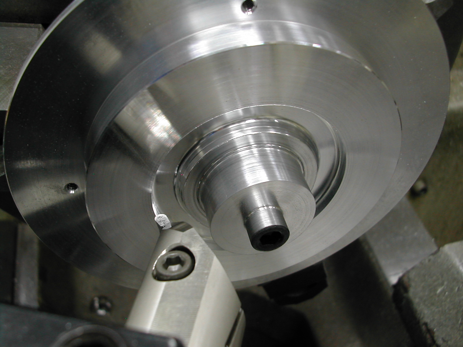
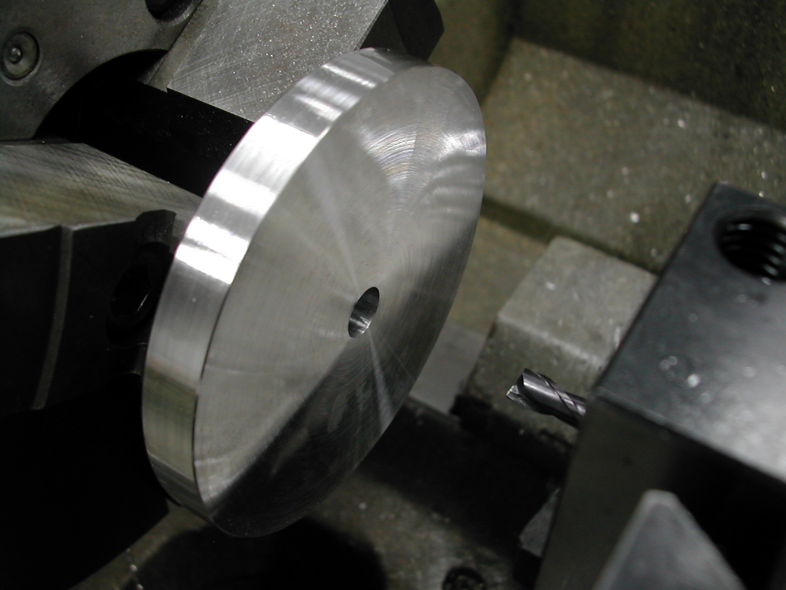 A 0.251″ hole was drilled and reamed through, followed by a 0.375″ counterbore 0.569″ deep. I really need to get some small solid-carbide boring bars someday, but for now an endmill works just fine.
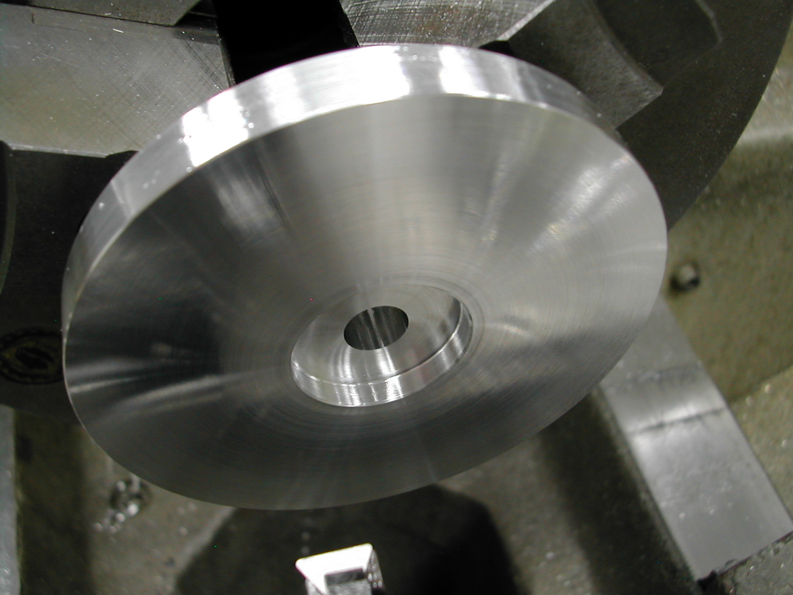 Finally the 1.000″ counterbore for clearance on the rear seal is added.
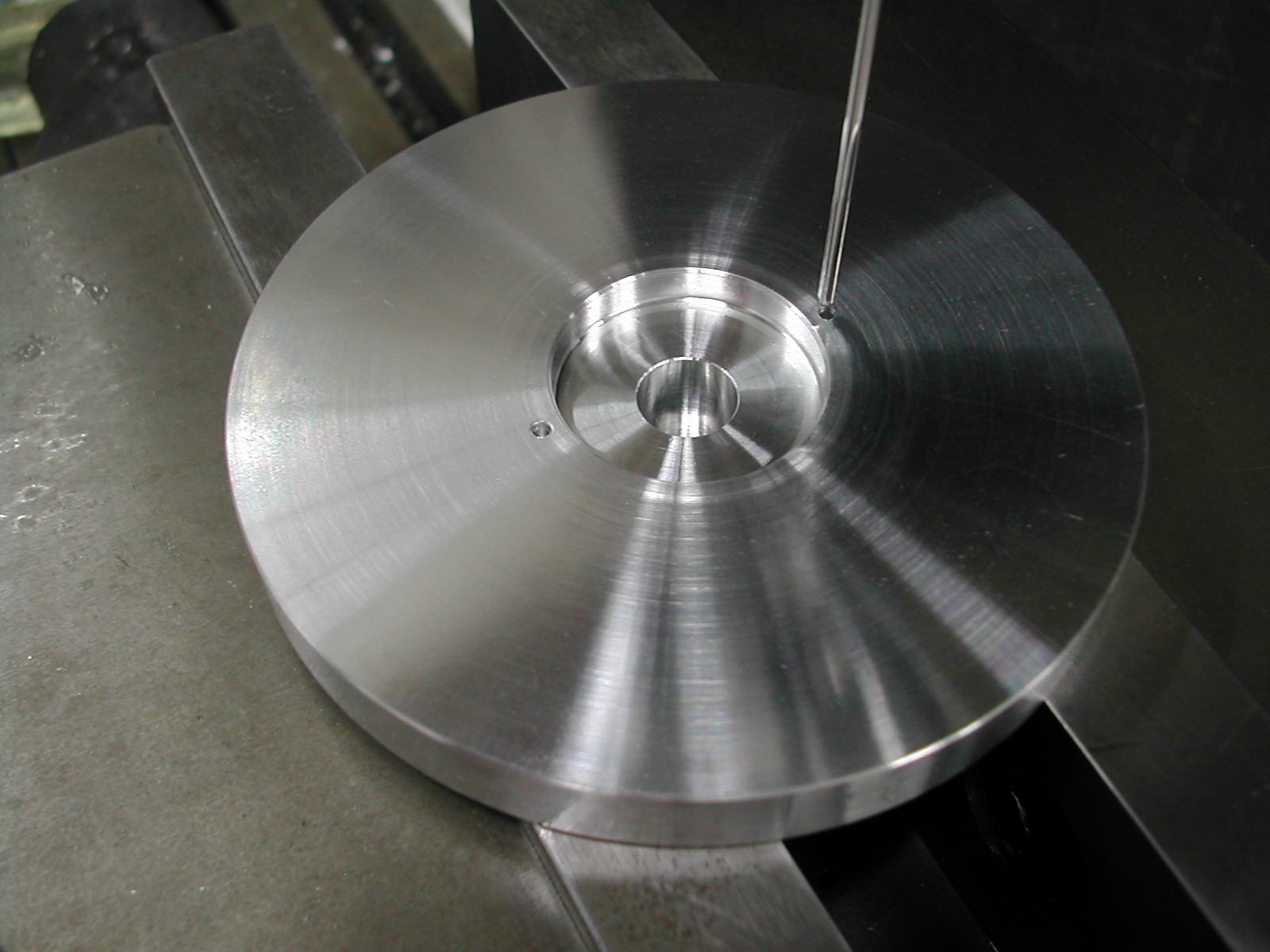 The plans call for a single drive-pin hole on the back, but I added a second to maintain balance on the impeller. Since I had some 1/16″ dowel pins, that is the size I made these holes. The only time they are used is with the special tool to machine the impeller blades (or in my case to machine the front side of the impeller as well).
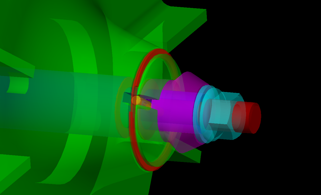
 With the back of the impeller finished, it can be mounted on the special tool to machine the front of the impeller. Besides the drive pin diameter change, I also changed the draw bolt from 1/4″-28 to a slightly smaller M4 since I was going in a 0.251″ reamed hole and I didn’t want to risk messing it up.
To prepare for machining the front of the impeller, I’m indicating in the finished O.D.
 Here I’m making two facing cuts to finish the overall length and the blade section thickness.
 The MGIUR toolholder mounts the insert at 45° to the shank. To clear the impeller angle I needed to set the insert at 20° to the impeller. Since this angle was just for clearance and was not critical, the easiest thing to do was to use an angle gauge to set the toolpost rotation.
 With the toolholder mounted, the next step was to make a test bore so I could measure the depth and diameter to preset the tool.
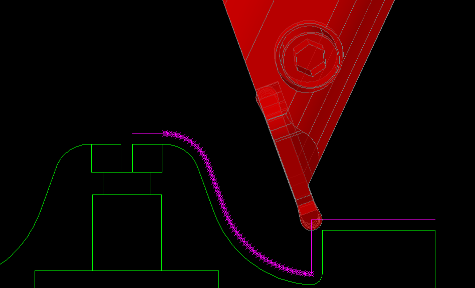
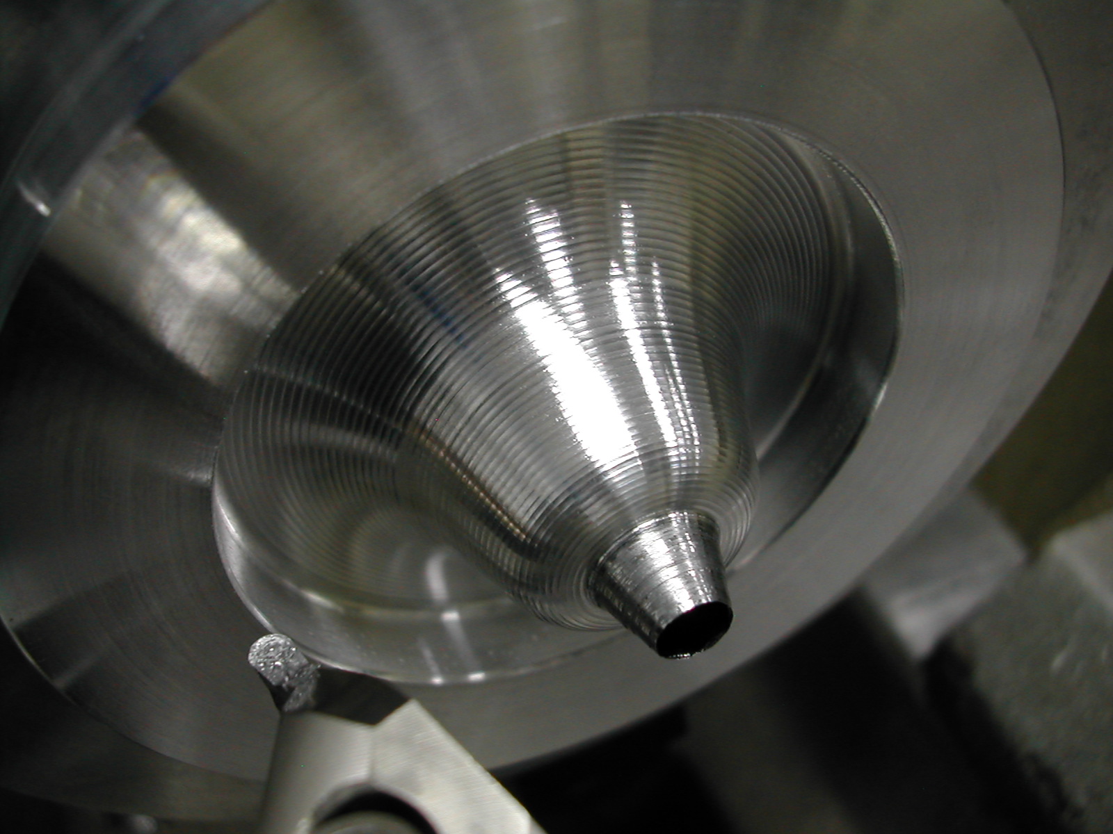 Following the X & Y coordinate data from the profile Excel spreadsheet , the impeller contour is generated. I had to make a some room on the M4 socket head cap screw to clear the toolholder. This leaves a scallop height of 0.0014″.
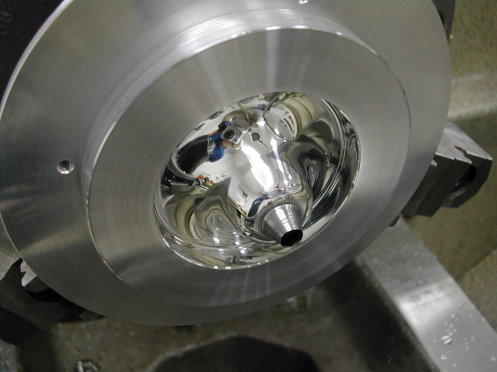
I ground the end of a file to use as a scraper to remove the scallops. This was followed with wet-or-dry paper in successively finer grits from 320 to 3000 grit, and then a final polish with some 3µ diamond paste on a tissue. It took less than 10 minutes to get to this finish after profiling and that includes grinding the file.
TO DO
- machine blades
- add counterbore for distributor miter gear
- add drive pin slot and retention ring groove
Disclaimer and License
All material, including the CAD drawings, relating to the construction of the Hodgson Radial presented on this site is free to use any way you see fit. However, no guarantees are made regarding the accuracy or correctness of the material presented here.
Links Used On This Page
(CAD drawings are in AutoCAD 2010 Format)