
- Hodgson Part 008, Cam Retainer Plate
- Hodgson Part 009/110, Cam Pad Support and Retainer Pad
- Hodgson Part 012, Cam Retainer Plate Spacers
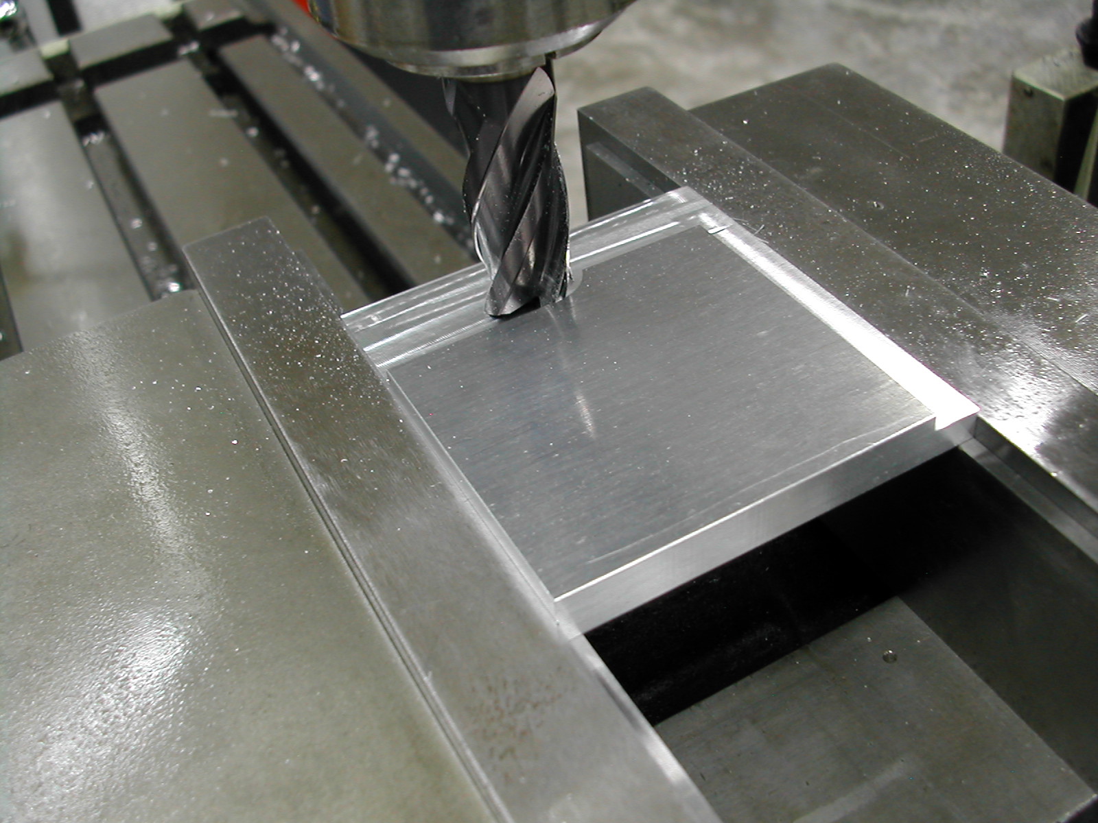 The cam retainer plate started life as a piece of 8mm thick 7075-T6 aluminum plate, so the first thing to do was to turn it into a 0.125″ thick piece.
Since I didn’t want to bow the material, I used very little clamping pressure and this necessitated using an endmill instead of my usual insert face mill to reduce the thickness.
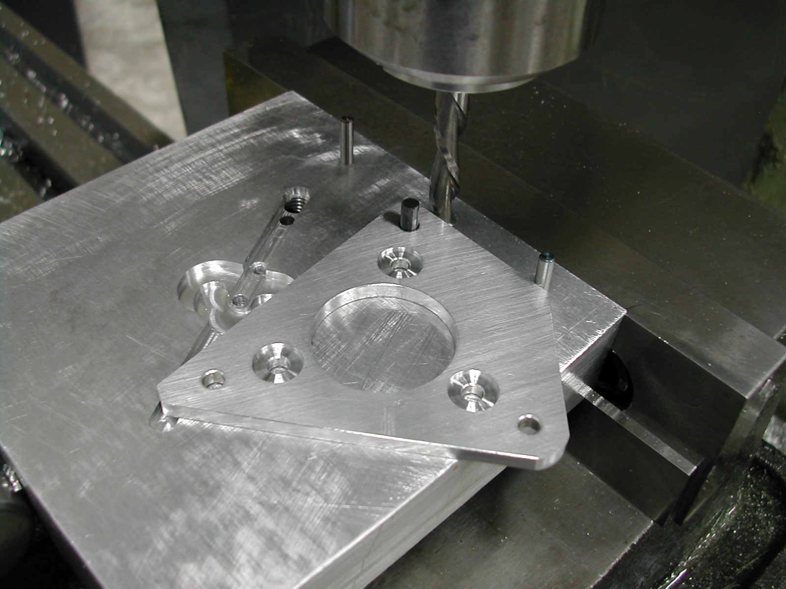
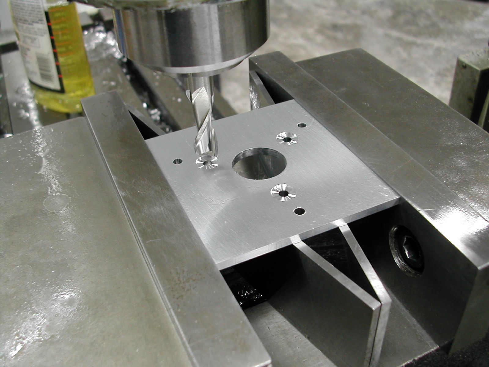 With the thickness reduced, I rough drilled the center hole and then drilled and reamed the six 0.144″ #6 clearance holes. I reamed them because I was going to use them later with a guide pin to round the corners.
I’ve also added three 11/32″ X 0.025″ deep counterbores at the spacer locations. I don’t like relying on a fastener clearance hole for location. By counterboring these places, the O.D. of the spacer will now provide positive location.
The bushing hole has been purposefully left out at this point and will be added later.
 This Wohlhaupter boring head was a $300 e-Bay find. It was just the bare head without any of the accessories, but it was almost brand new – the Cosmoline was still on it! I’m using it to finish off the 1.000″ center hole.
 The plate and I made a quick trip to the bandsaw where the excess stock around the perimeter was removed.
 The two long sides were easy to clean up. I just used a couple of 1/8″ dowel pins in the fastener holes to align the plate relative to the top of the vise jaws and then milled to 0.180″ above the top of the dowel pins.
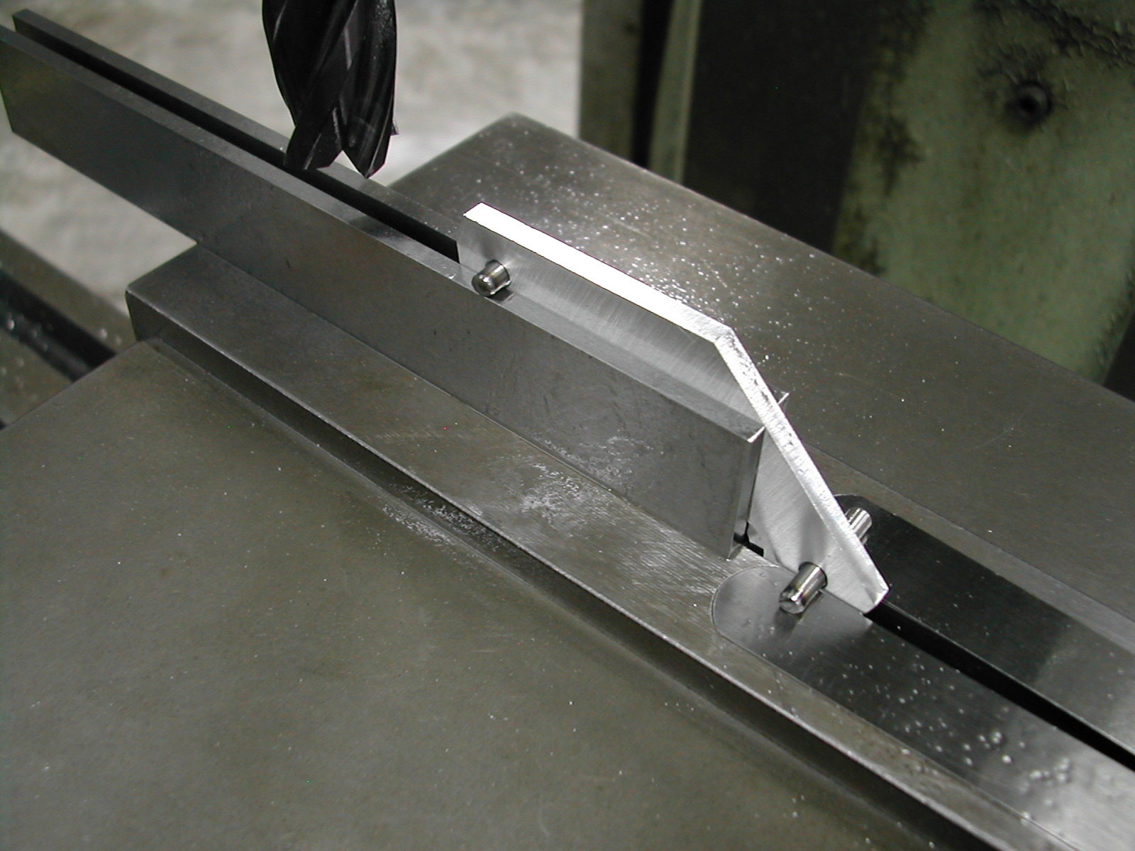 The shorter sides were a little more of a problem. I needed to elevate one dowel pin 0.775″ above the other to cut the correct angle. Lacking a 0.755″ spacer, I used a pair of 20mm parallels and then shimmed the other dowel pin up with some 0.95mm feeler gages.
The side was then cut to 0.180″ above the upper dowel pin. The part was reversed and this was repeated for the other short side.
Here’s an AutoCAD 2010 sketch 008 Plate Layout of the part showing how these distances were calculated.
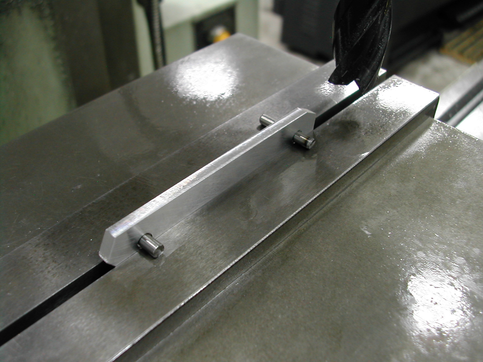
 I used a scrap piece of aluminum, a 0.144″ drill bit, and a couple of 3mm dowel pins to make a quick rounding jig to route the corners. I’m using a 1/4″ carbide down-cut router bit to prevent the part from climbing up the bit and off the axle.
The two 3mm pins are stops to prevent me from overcutting at the beginning and end of the cuts.
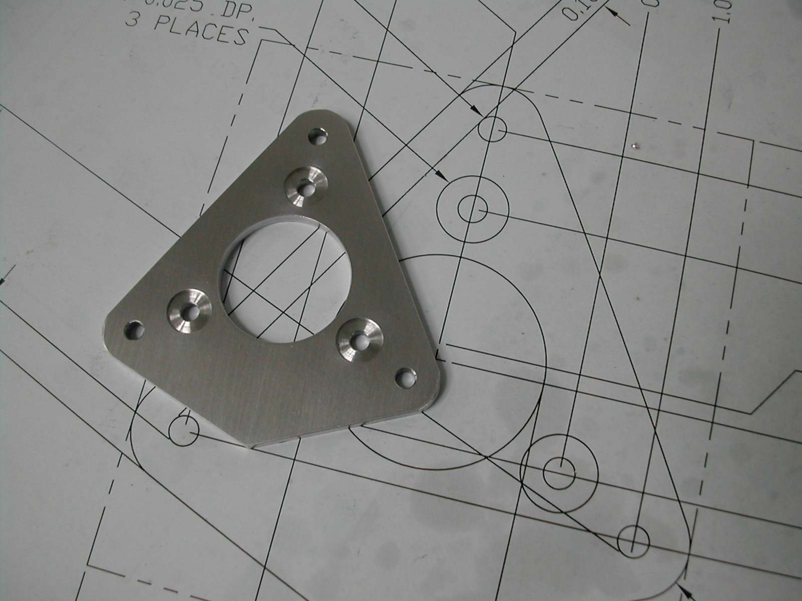
 Here the cut is finished and the part is up against the second stop. I roughed all three corners with the router bit backed off 0.005″ then went back and took a 0.005″ finish cut on each corner.
 At this point, the only thing left is the bronze bushing for the jackshaft.
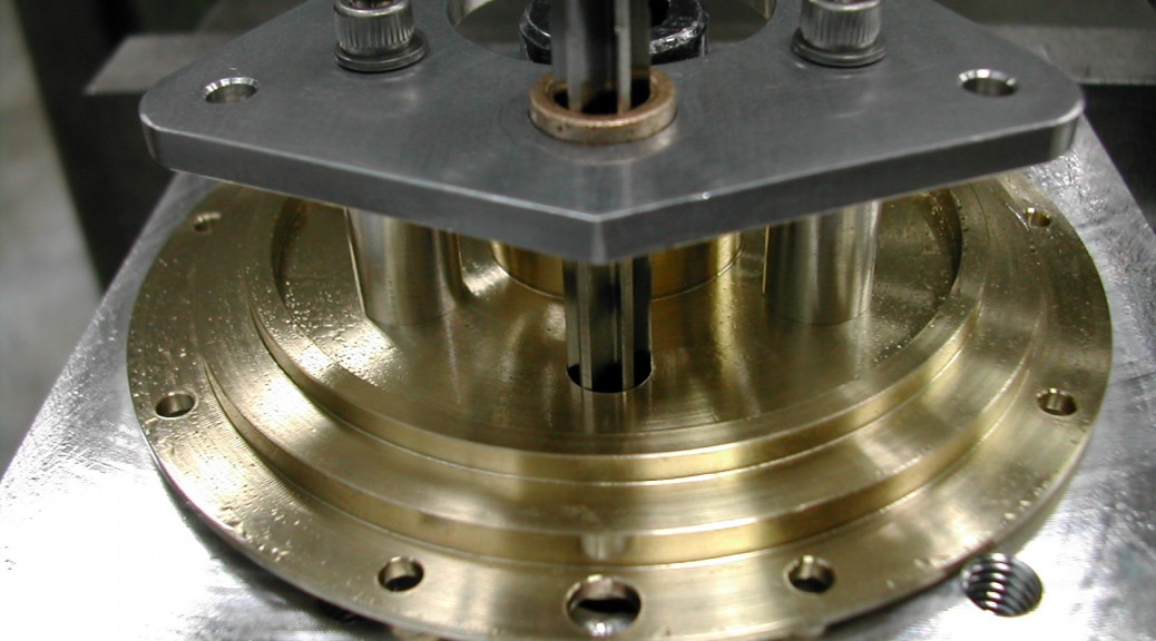
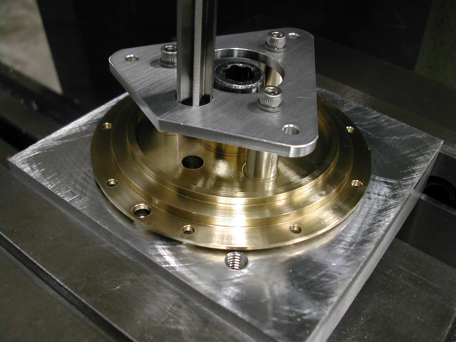
 Here, I’ve just finished drilling and tapping all of the holes in the front main bearing. With the bearing still clamped in the drilling fixture, I’ve assembled the retaining plate onto the front main bearing and the hole for the bronze bushing can now be drilled.
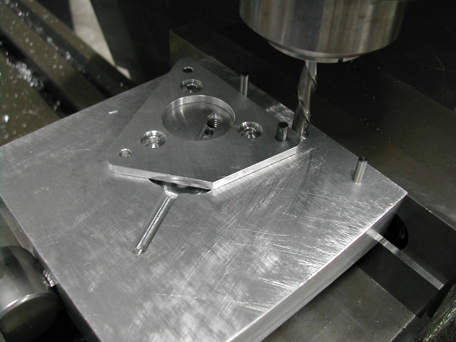
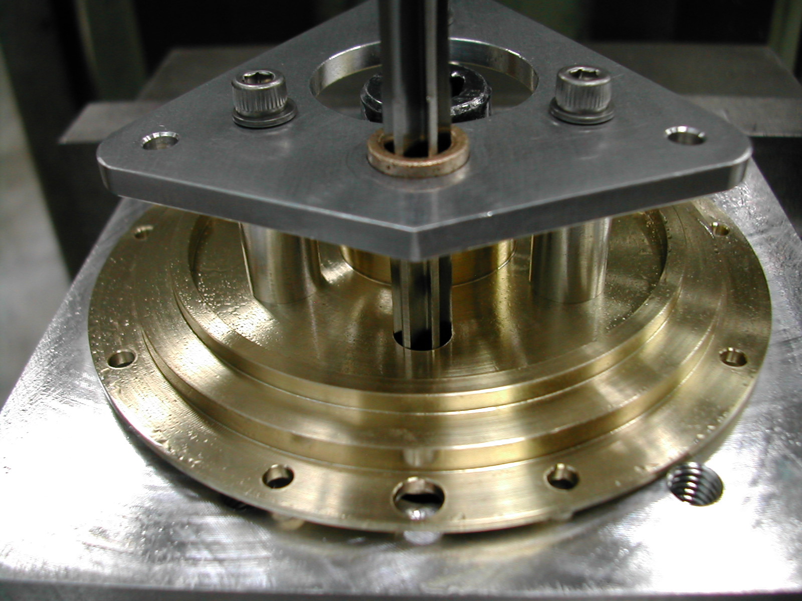
I’ve roughed out the hole for the bronze bushing and now I’m rough drilling the jackshaft hole in the front bearing plate.
 A 0.375″ reamer prepares the cam retainer plate to receive the bronze bushing. The Oilite bushing was a McMaster-Carr part, #6338K411.
 The bushing was coated with Loctite RC680 retaining compound and a draw-bolt was used to pull it into place without removing the plate from the bearing.
 After the Loctite had time to cure, a 0.251″ reamer was run through both the bushing and the front bearing at the same time.
I used a 0.251″ reamer instead of the 0.250″ specified in the plans because I wanted to be sure the bronze bushing cleaned up. I’ll just need to make sure the jackshaft is sized accordingly.
Disclaimer and License
All material, including the CAD drawings, relating to the construction of the Hodgson Radial presented on this site is free to use any way you see fit. However, no guarantees are made regarding the accuracy or correctness of the material presented here.
Links Used On This Page
(CAD drawings are in AutoCAD 2010 Format)