 My TIG welder has a water-cooled torch. Being water-cooled, it is lighter and easier to maneuver than an air-cooled torch because a much smaller water-jacketed welding lead can be used to carry the welding current. The downside is without cooling water flow, the smaller welding lead will overheat and melt the cooling water hose. This can be an expensive problem as I discovered while welding the radiator shroud for my backhoe.
My torch cooling water is supplied by a Miller WaterMate 1A chiller. The WaterMate comes with a simple sightglass to verify cooling water flow. It is, however, not in an easily visible location while welding. Should the cooling water hoses become blocked or pinched cutting off coolant flow while welding….
As I was welding my radiator shroud, my TIG cart rolled forward onto my welding lead with now predictable results. After purchasing a new TIG torch and hoses, I sought a way to prevent this from happening again. On some projects at work, I’ve used RotorFlow sensors to monitor fluid flow and I figured I could use one to monitor the chiller output and sound a horn if the cooling water flow dropped while welding. I scored one at a good price off eBay and this project was on a roll!
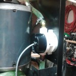 This program and the simple circuit board that accompanies it, are designed to monitor the flow of cooling water and provide an audible alert if water flow is interrupted. The RotorFlow I scored on eBay (P/N RFO155421) was rated for flows from 0.1 to 5 GPM, and my new torch had a cooling flow requirement of 1L/min. After mounting the flow meter in the WaterMate chiller just above where the original sight tube was located, the next step was to verify the correct coolant flow and measure the frequency output of the sensor at this flow.
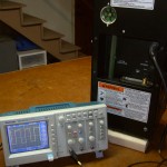 With the TIG torch and accompanying 25′ hoses connected to the WaterMate chiller, I temporarily disconnected the return hose at the chiller and measured the time required to fill a 1L container. At 62.69 seconds, it was just outside the recommended flow rate, but I was confident it was close enough. After reconnecting the chiller return hose, the next step was to connect a 9V battery and my oscilloscope to the Hall-Effect sensor in the RotorFlow and measure the output frequency. Normally, I would take multiple frequency/flow readings to calibrate the sensor, but for what I had planned, it was good enough to note the 39-41Hz reading at full flow and around 20Hz using a C-clamp to pinch the hose and restrict the flow to approximately half. While testing, I also noted that it takes about 5 – 10 seconds after the pump on the WaterMate starts before stable coolant flow is established.
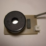 With the baseline measurements complete, it was time to begin designing the hardware and firmware to control my new alarm. I salvaged a nice loud Piezo horn from and old smoke detector and was able to locate a datasheet for it on the Web. The datasheet contained a test circuit for the piezo so half my work was already done.
What I wanted to create was a device that powered up when the chiller was turned on. It would wait approximately 15 seconds and then begin to monitor the flow. If the flow drops to an unacceptable level, the buzzer should beep to alert me. Once flow is restored, the buzzer stops and the device is again monitoring flow. To verify both the program and the alert buzzer are operating correctly, the piezo should chirp once every 2-seconds during the initial 15 second start-up phase..
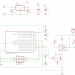 The easiest way to accomplish this would be with a small µController. To monitor the flow, I need to measure the pulse width of the hall-effect sensor output and the easiest way to do this is with an Input Capture interrupt tied to a timer. The length of the pulse is inversely proportional to the flow rate. Shorter pulses = higher flow rates. If the timer counter value is larger (longer pulse) than minimum flow or if it overflows (really long pulse) the piezo output will be turned on. Counter values less than a minimum flow (short pulses) will turn the piezo off. A simple circuit was designed in EagleCAD and breadboarded to test.
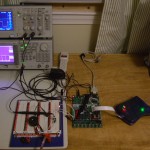 This is a very simple program needing only a single input and a single output. I/O will not be a problem, but to use ICP, we need a 16-bit timer/counter. The smallest pin-count AVR with a 16-bit T/C is the ATtiny24/44/84. The program will easily fit in the 2K flash of the ATtiny24, but with pricing of $1.45/$1.65/$1.91 respectively, for a hobbyist it does not make sense to keep anything other than the 8K flash part on-hand.
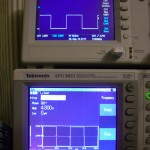
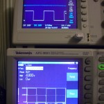 During testing, a signal generator stood in for the Watermate and RotorFlow sensor. On the scope displays, the upper scope trace is the piezo output, and the lower trace is the simulated flow signal. The left image shows the piezo output off when a 20Hz signal is present, and the right shows the output on in the presence of a 19Hz signal.
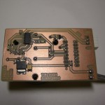 Once the circuit and program code (Atmel Studio project) were verified, a quick PCB was made using the toner-transfer method in the kitchen sink. On this side of the board you can see the µController in the upper left with an LDO linear regulator below it to provide 5V for the logic.
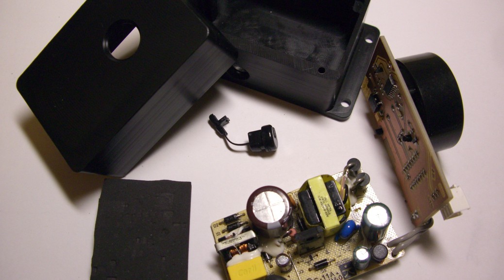
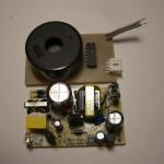 The piezo needed 12V to operate, so a 12VDC switch-mode wall-wart was cannibalized and the circuit board removed. This was wired directly to the alarm board and 120VAC was taken from the WaterMate power switch.
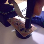 Since the µController was soldered directly to the PCB and there was not room to include a regular ICP header, the header footprint was included on the back side of the board and a pogo-pin programming probe was used to upload the firmware to the device.
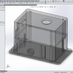
 An enclosure for the two PCBs was modeled in SolidWorks and machined from Delrin.
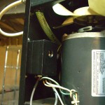 The enclosure was then mounted inside the WaterMate chiller cabinet and connected to the RotorFlow sensor and the chiller’s power switch.

