
- Bike Light Battery Pack Adapter
- Bike Light Housing
- Bike Light Electronics Package
With the battery assembly done, I turned to …
The Light Housing
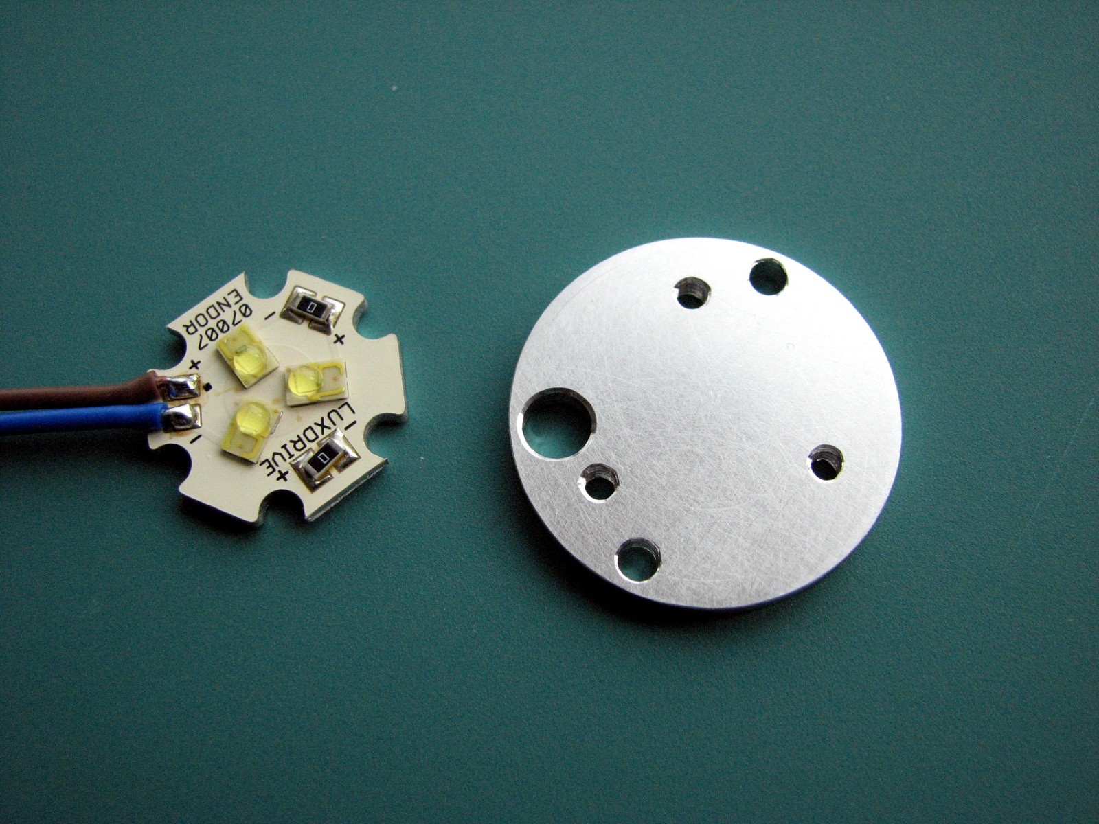
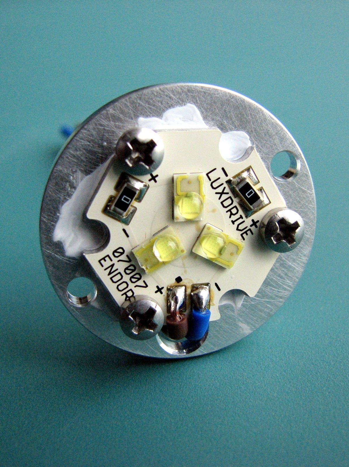
 The Endor Rebel LED generates some heat as we pump 0.7A through it at 9V. Therefore, it needs a heatsink, so that pretty much means the housing we design needs to be made out of Aluminum and needs good physical contact with the LED’s aluminum base. So, again we start with a 3D CAD model. The first thing we need to do is model the actual Rebel LED since everything else grows from there.
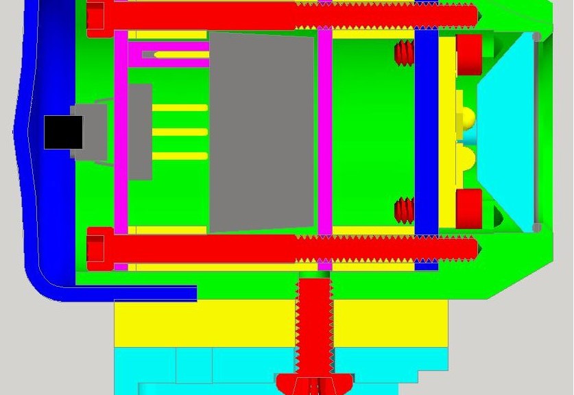
Since the BuckPuck supply was a nice compact design, I envisioned combining the LED emitter (yellow object on right) and lens (cyan pyramid on the right), power supply (gray rectangle in the center), and control circuitry (PCB is magenta on the left), in one package. The challenge was how to keep this entire package water resistant. To keep the water out, I’ve sealed the lens to the housing (green) with a 21mm OD x 1mm thick O-ring (gray), and covered the electronics end with a vinyl cap (blue). The flexible vinyl cap (Mocap P/N HT201-002 1.250″ Dia x 0.5″ long high temperature vinyl) also lets us operate the dimming pushbutton (black square and gray rectangle on left) simply by pressing the outside of the cap.
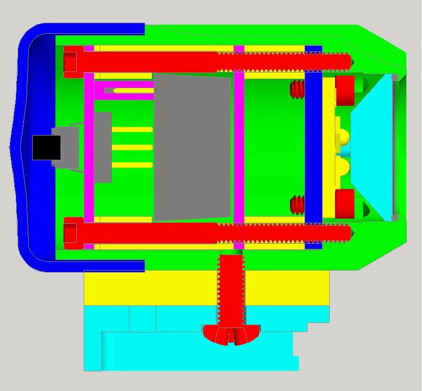 The cyan part at the bottom of the image above is one of the lucky finds on this project. My wife’s bike has a little CatEye single LED light. It’s okay for around the town where there are streetlight to light the way and the bike light is really only used for others to see you, but it has a great mounting system. A quick check of their website turns up replacement parts – you can get the complete handlebar mount for around $5.00 (H-32 Bracket and spacer)!
The blue plate just left of the LED emitter is a heat conductor. It conducts the heat from the LED to the outer case. While making the light water resistant was one challenge, the biggest one was fitting all the parts in such a small space and mechanically fastening the who assemble together. As you can see, the red screws take up a lot of the space and the ones inside the housing are already #4-40, so I didn’t have a lot of room to throw in a bunch of fasteners.
The whole thing is held together by the two screws on the left. Those pass through the PCB, then a spacer which locates the BuckPuck retaining plate which goes on next, and finally another short spacer. This all presses up against the heatsink plate and threads into the housing squeezing everything together. A little thermal grease behind the LED and a little more around the face of the heatsink plate where it seats against the housing, insure that the LED stays below the smoke point.
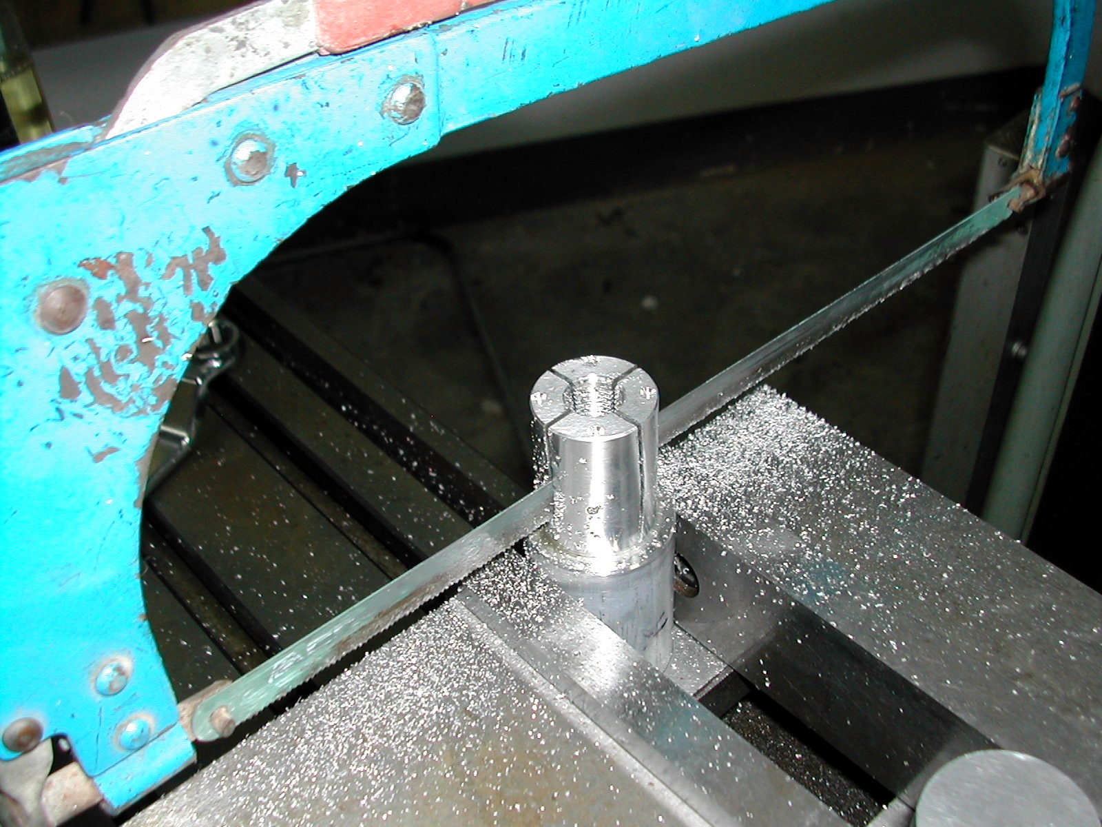
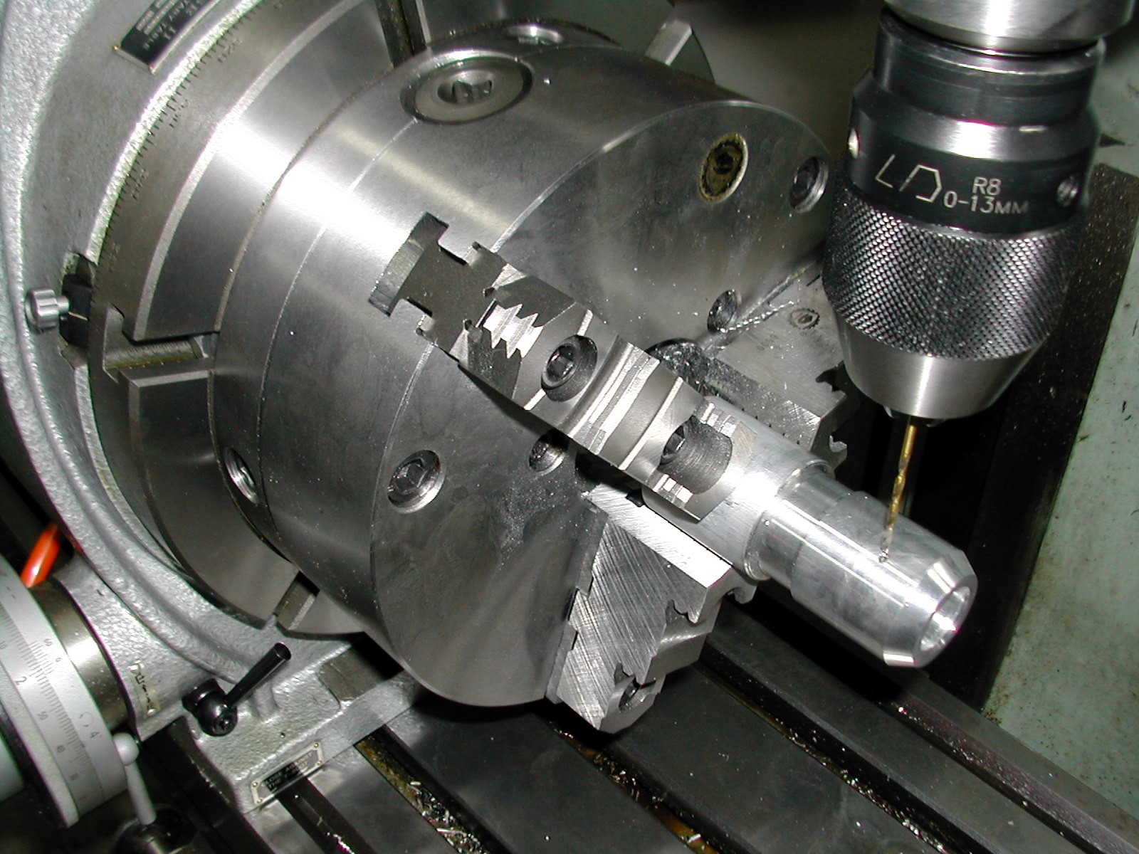
Below is a parade of pictures machining the housing. First I started with the LED mounting plate, then onto the internal portion of the housing. Because of the partial holes in the housing needed to clear the LED mounting screws, those holes need to be drilled before the bores are made. So, the stock was faced off in the lathe then moved to the mill where the six small holes were drilled. Then, back to the lathe for finishing the internal boring. The part was then sawn off from the stock. The remaining stock was used to turn a mandrel that was first used to turn the OD of the PCB.
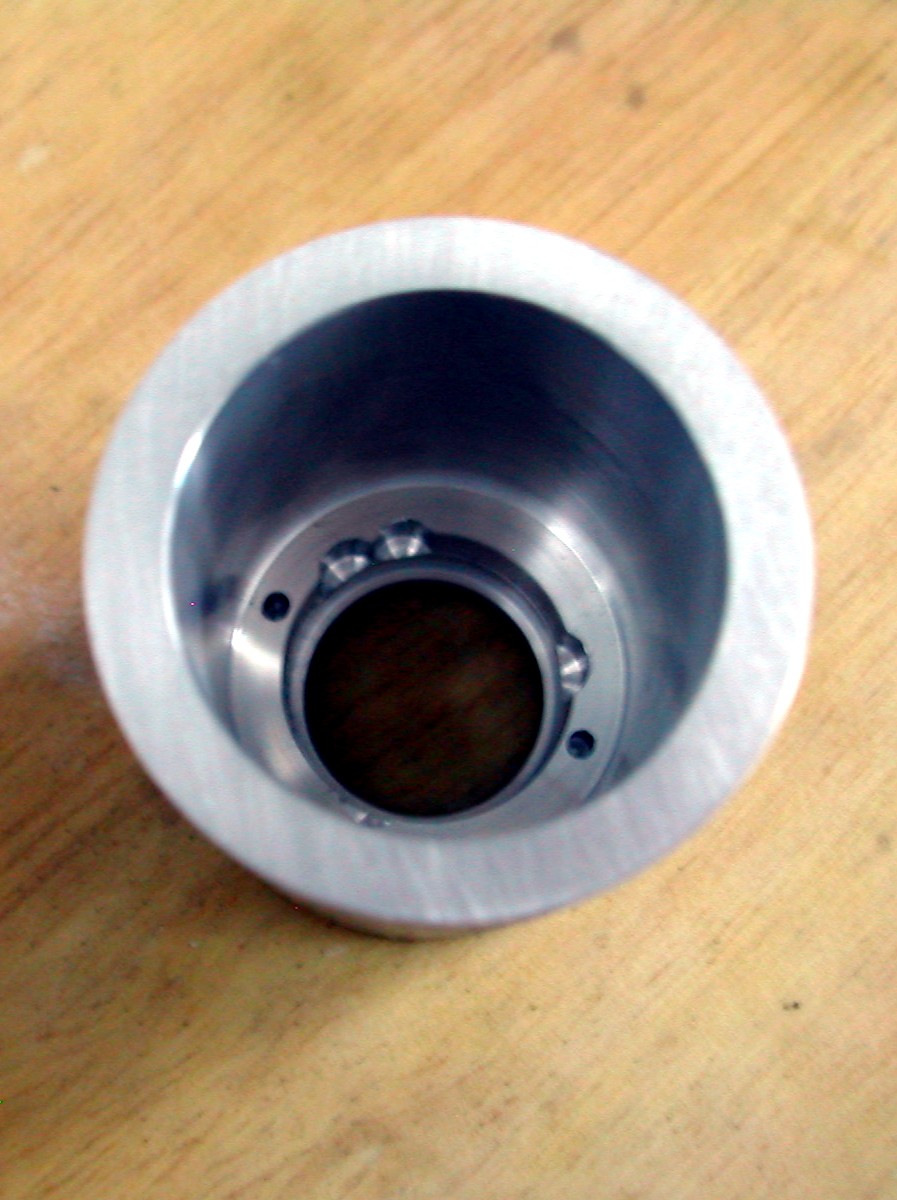
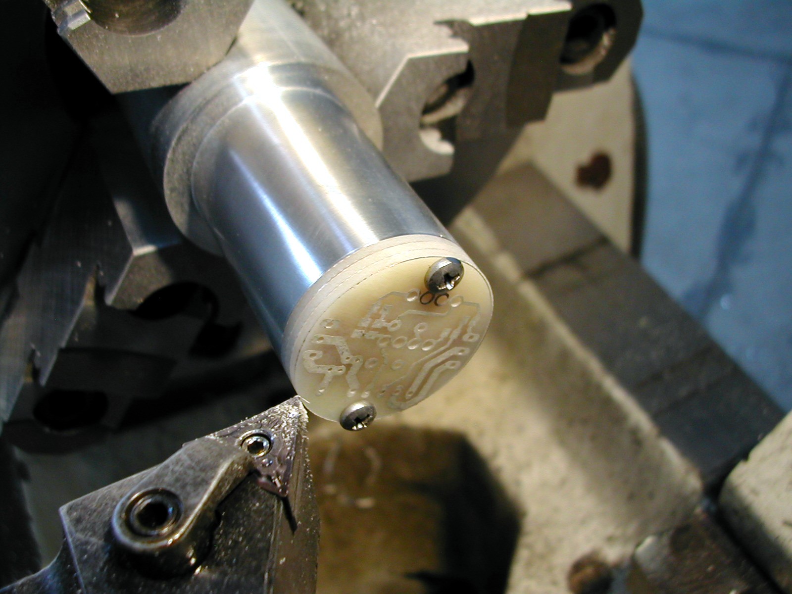
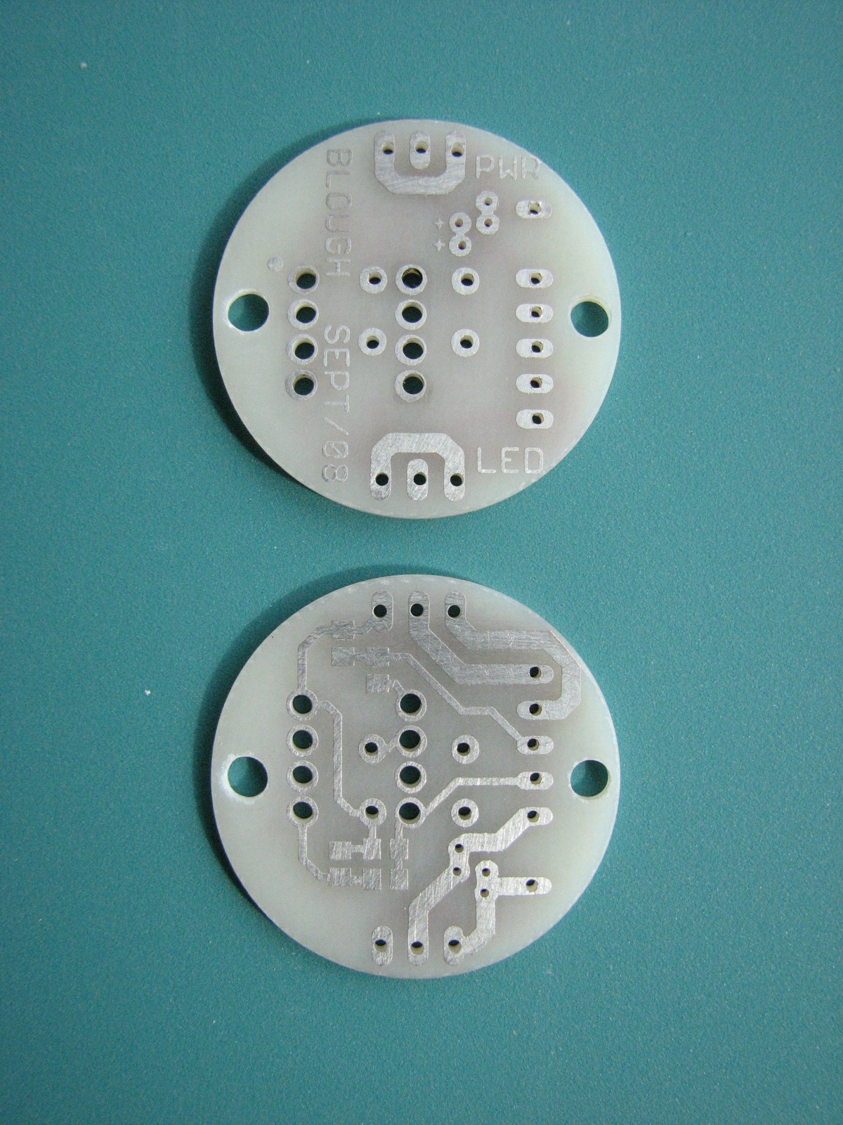
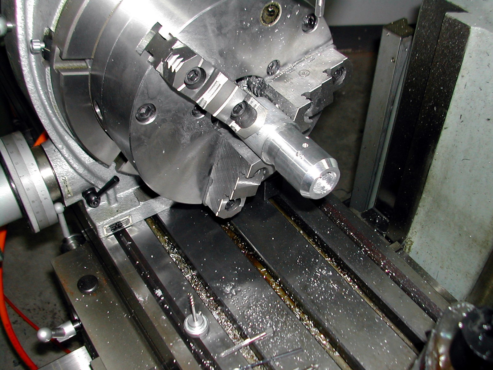
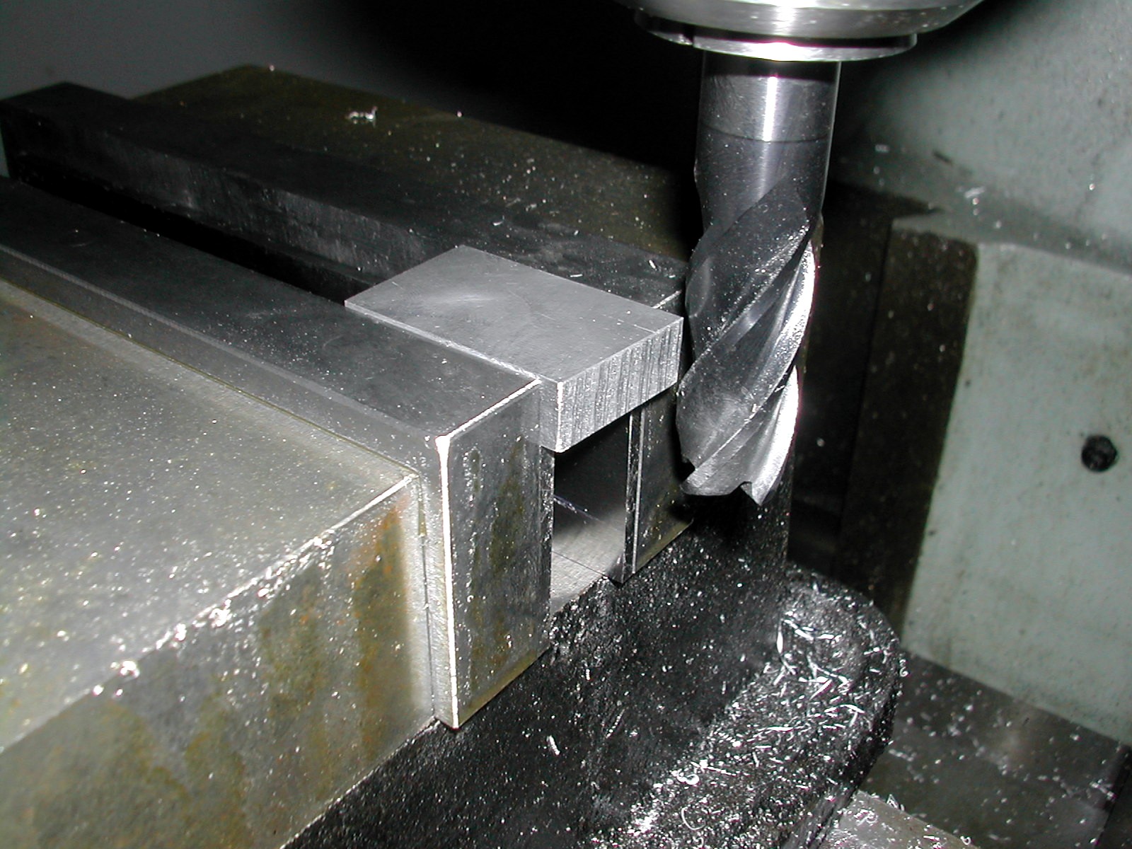
The mandrel was then split and a pipe plug was used to make it an expansion arbor. Short pins were inserted in the tapped holes used to mount the PCBs. These pins located the #4-40 tapped holes in the housing interior, and the whole thing transferred back to the lathe to turn the housing OD Back to the mill and the mandrel and part are mounted on a rotary table to add the holes to the outside and do the finning.


The final piece to be machined was the CatEye mount adapter (yellow at bottom of the section image). These two are aluminum, but the one in the assembly photos was machined from some scrap Delrin left over from battery housings.
One change from the CAD model was the substitution of Phillips pan head screws for the SHCS that were modeled. Again this was necessitated by availability and required turning down the OD of the fastener heads. Phillips #4-40 screws are also used to secure the CatEye adapter plate to the bottom of the housing. The heads of these screws must also be turned as the fit into recesses on the top of the CatEye spacers to prevent the spacer from turning.
Next post: the electronics.
Disclaimer and License
It worked for me so it should work for you, but no guarantees. Feel free to use the schematics, drawings, and information on this page as you see fit, but a little attribution would be appreciated.
Project Sources
- AVR Studio GCC Source (14K .zip)
- Cadsoft Eagle Files (65K .zip)
- AutoCad 2008 Model (3.8M .zip)