The steps below will guide you in creating realistic and accurate threads in SolidWorks. You probably will not want to do this every time as it will greatly increase the part size and load time, but it is necessary if you plan on 3D printing or molding your part.
This procedure will generate accurate theoretical UN Inch or M metric threads without clearance (class 3/4H) having largest external thread and smallest internal thread (i.e. Maximum Material Condition [MMC])
“D” = Basic diameter (i.e. for 1/4-20 thread = 0.250″)
“P” = Thread Pitch = 1/TPI (i.e. for 1/4-20 thread =1/20 = 0.050″)
Below we’ll create an example 9/16″-18 thread 11/16″ long.
External Thread
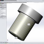
- Create cylinder with diameter = D
(optionally select diameter between maximum external major diameter and minimum external major diameter [Machinery’s Handbook, 28ed, pp1723, 1774] for appropriate class thread) - Chamfer beginning of thread 30° with long side >= 0.5953925*P
- Add thread relief at end of thread, if needed, with diameter <= D – 1.08253175*P
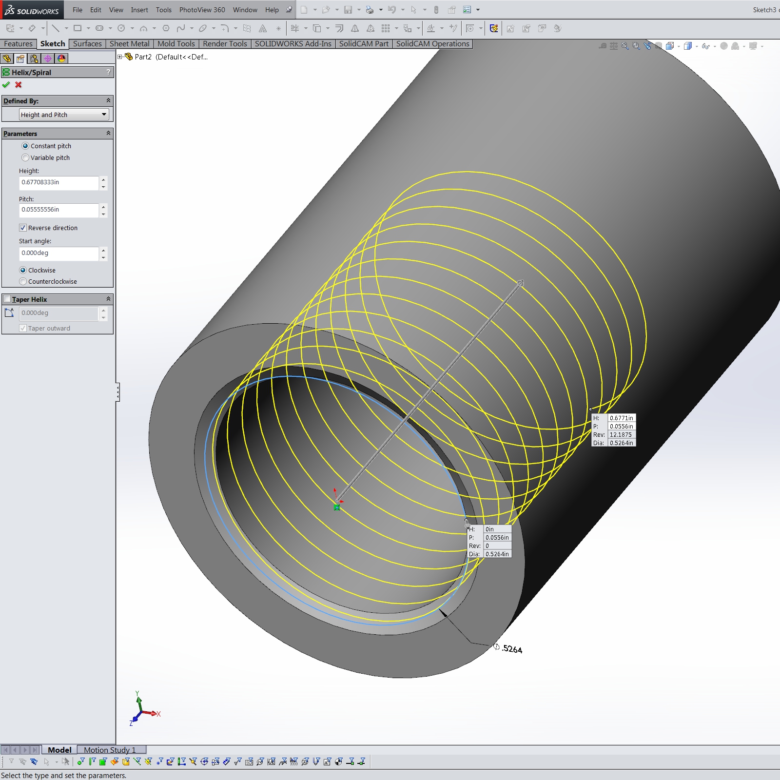
- Insert / Curve / Helix/Spiral
- select the end face of the cylinder to define the helix cross-section
- sketch pitch circle diameter = D – 0.64951905*P
(optionally select diameter between maximum external pitch diameter and minimum external pitch diameter [Machinery’s Handbook, 28ed, pp1723, 1775] for appropriate class thread) - exit sketch
- select Height & Pitch and Constant pitch for the helix
- Height = length of thread – 0.1875*P
- Pitch = P
- Start angle = 0
- choose Clockwise/Counterclockwise to match the thread handedness
- select OK to exit the helix dialog
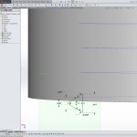
External Thread Helix
- Select the endpoint of the helix and then the helix curve
- Insert / Reference Geometry / Plane
- select OK
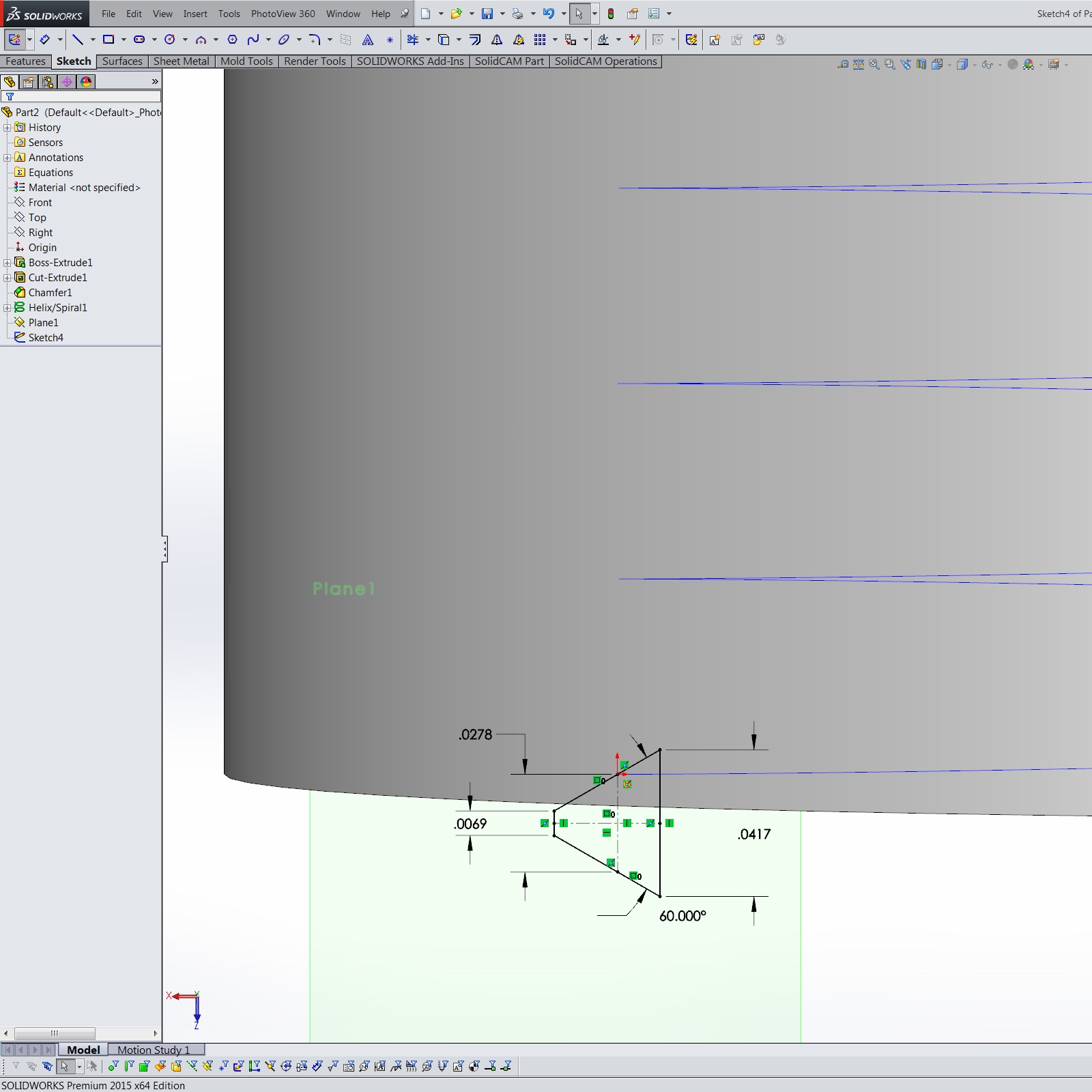
- Create a sketch on the new plane
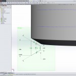
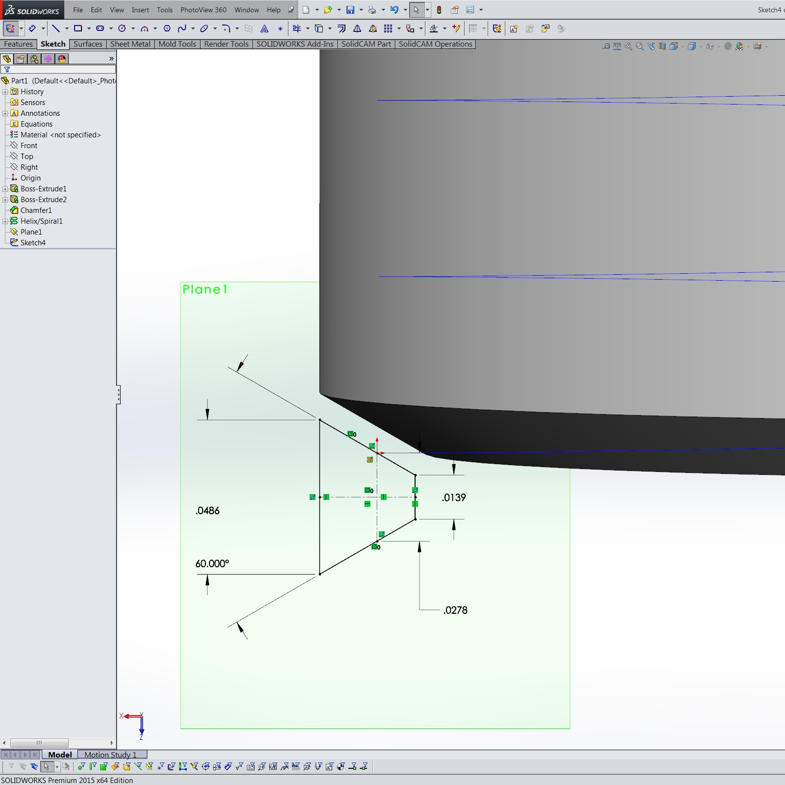
- sketch a trapezoid with the short side towards the center of the cylinder and parallel to the axis of the cylinder
- connect the middle of the short side with the middle of the opposite side with a construction line and make it perpendicular to the axis of the cylinder
- make the two angled sides symmetrical with the construction line
- link the two angled sides with a construction line parallel to the short side
- dimension the short side = 0.25*P
- dimension the opposite side = 0.875*P
- dimension the construction line in “d” = 0.5*P
- dimension the angle between the two symmetrical sides = 60°
- select the helix and the near endpoint of the construction line connecting the angled sides and create a Pierce relation
- exit the sketch
External Thread Profile
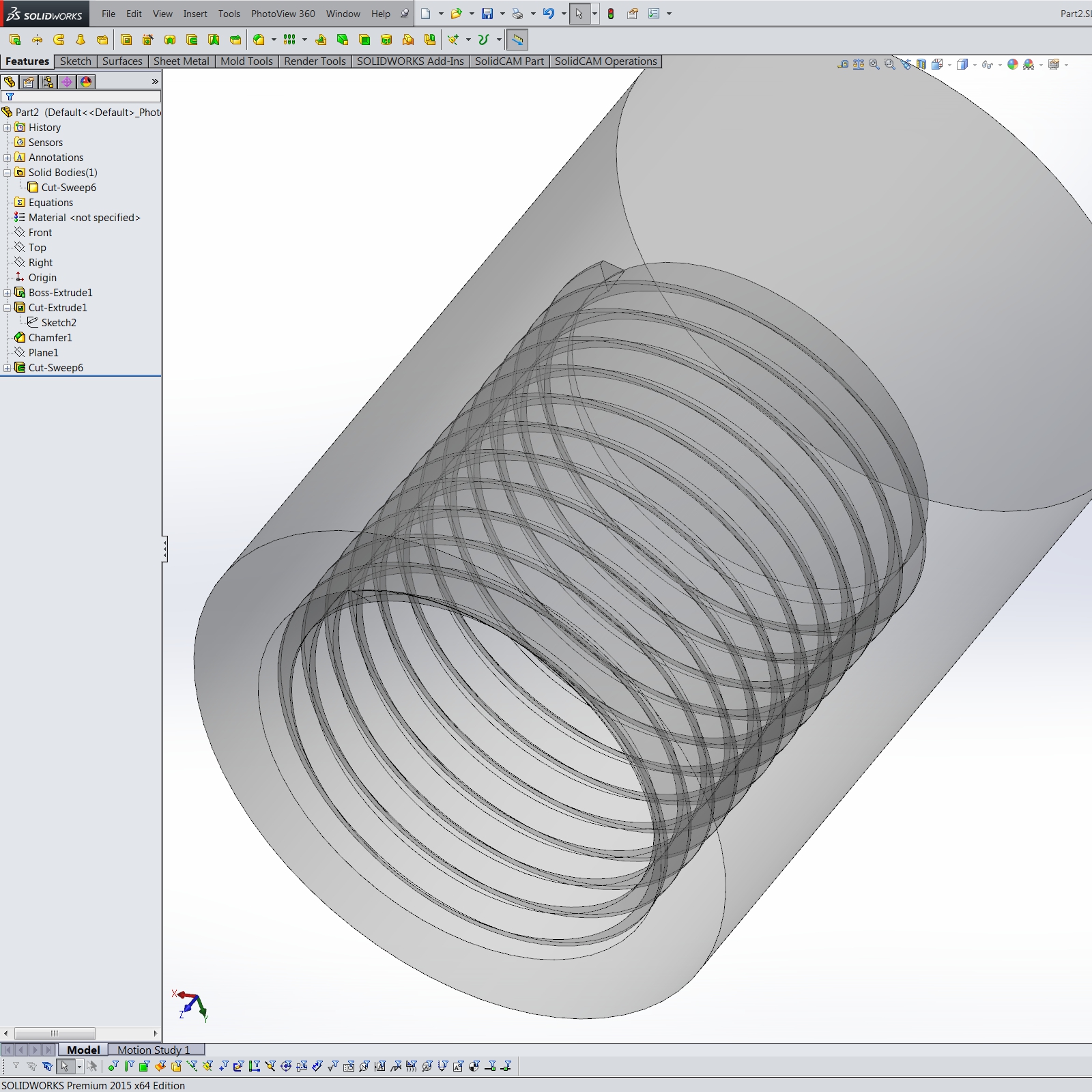
- Hide the plane created in step 5
- In the feature tree, select the previous sketch and the helix
- Insert / Cut / Sweep…
- select OK
(You may end up with multiple bodies after the cut sweep due to rounding errors in SolidWorks. If so, select the threaded body to keep, and delete the remaining thin skin over the threads.)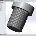
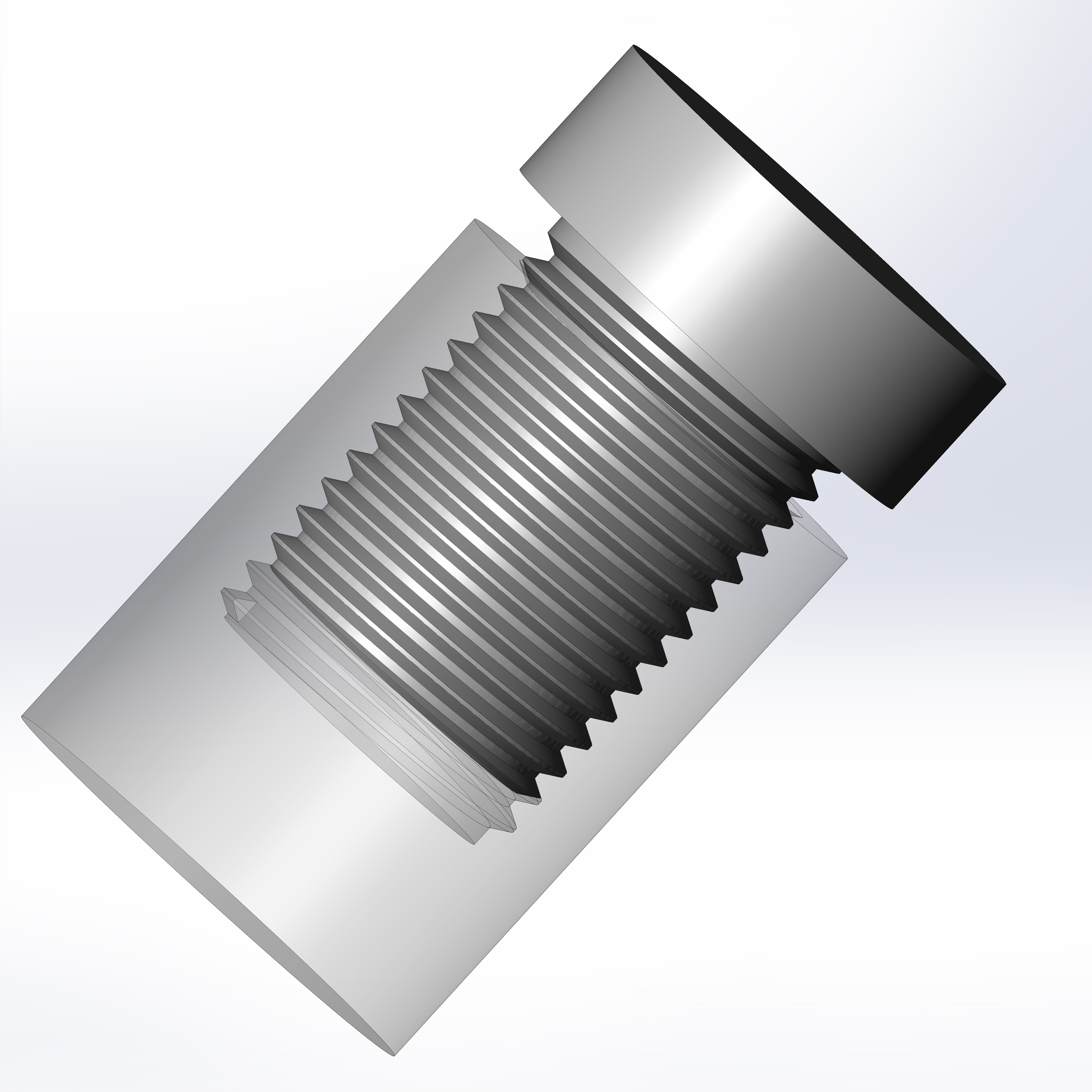
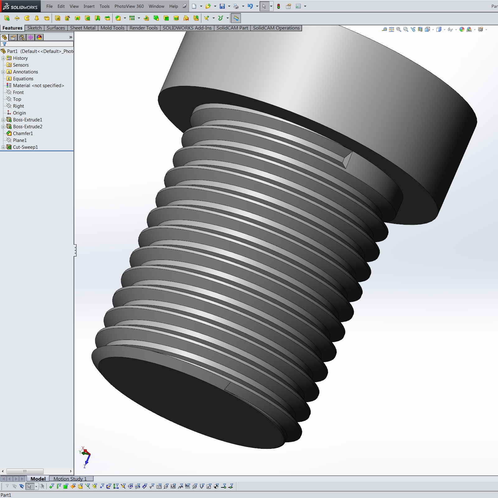
External Thread

Internal Thread
- Create round hole with diameter = D – 1.08253175*P
(optionally select diameter between minimum internal minor diameter and maximum internal minor diameter [Machinery’s Handbook, 28ed, pp1723, 1776 for appropriate class thread) - Chamfer beginning of hole 30° with long side >= 0.5953925*P
- Add thread relief at bottom of hole, if needed, with diameter >= D
- Insert / Curve / Helix/Spiral
- select the face at the start of the hole to define the helix cross-section
- sketch pitch circle diameter = D – 0.64951905*P
(optionally select diameter between minimum internal pitch diameter and maximum internal pitch diameter [Machinery’s Handbook, 28ed, pp1723, 1777] for appropriate class thread) - exit sketch
- select Height & Pitch and Constant pitch for the helix
- Height = length of thread – 0.125*P
- Pitch = P
- Start angle = 0
- choose Clockwise/Counterclockwise to match the thread handedness
- select OK to exit the helix dialog
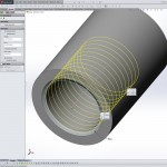
Internal Thread Helix
- Select the endpoint of the helix and then the helix curve
- Insert / Reference Geometry / Plane
- select OK
- Create sketch on the new plane.
- sketch a trapezoid with the short side towards the outside of the hole and parallel to the axis of the cylinder
- connect the middle of the short side with the middle of the opposite side with a construction line, and make it perpendicular to the axis of the cylinder
- make the two angled sides symmetrical with the construction line
- link the two angled sides with a construction line parallel to the short side
- dimension the short side = 0.125*P
- dimension the opposite side = 0.875*P
- dimension the construction line in “d” = 0.5*P
- dimension the angle between the two symmetrical sides = 60°
- select the helix and the near endpoint of the construction line connecting
- the angled sides and create a Pierce relation
- exit the sketch
Internal Thread Profile
- Hide the plane created in step 5
- In the feature tree, select the previous sketch and the helix
- Insert / Cut / Sweep…
- select OK
(You may end up with multiple bodies after the cut sweep due to rounding errors in SolidWorks. If so, select the threaded body to keep, and delete the remaining thin skin over the threads.)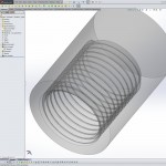
Internal Thread