
Details 06 & 07, the Tool Holder Arm and Head
 I started with Detail 07, the Tool Holder Head. The spindle housings should fit in the head without slop but still be easy to turn. To accomplish this they need to be a very close fit with good surface finished. It will be much easier to sand/lap the spindle housings to fit whatever size the bores turn out in this part than it would be to hone the bores without them becoming bell mouthed. So this piece of Ø1.5″ material needs to get squared up so we can get started.
 With 0.250″ taken off of the first side, the part is rolled and 0.163″ is taken off the second side.
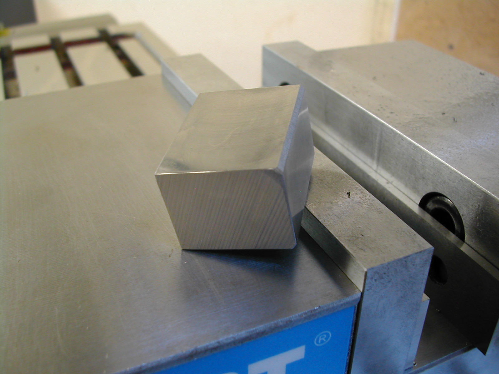 For the next two rolls, we cut to the finished dimensions of 0.875″ and 1.094″ respectively. It doesn’t matter that two of the corners haven’t cleaned up as these will get taken down when the dovetail is cut.
 At this point many would switch from the face mill to an end mill to clean up the ends. I’m about to show you a trick to do everything with the face mill, save a tool change, end up with the same surface finish on all sides, and with all sides perfectly 90° to each other. While this only works with comparatively cubic shapes, this part fits the bill.
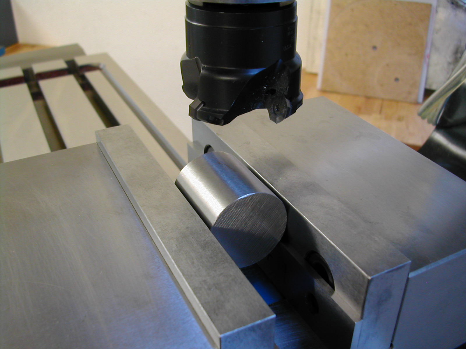
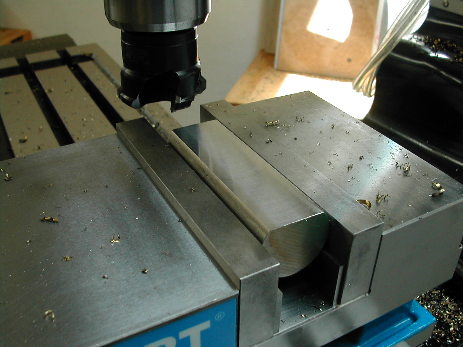
Start by placing the shortest finished side against the vise jaw. Use only one parallel along the back to raise the part up for clearance and try to get the block as close to vertical as you can but it’s not critical. Mark the long side at the top with a magic marker. Once we take a skim cut to clean up the top, the side with the mark will be 90° to front/back of the part (the sides against the vise jaws) but will not be square to the sides of the part. We’ll fix that in a minute.
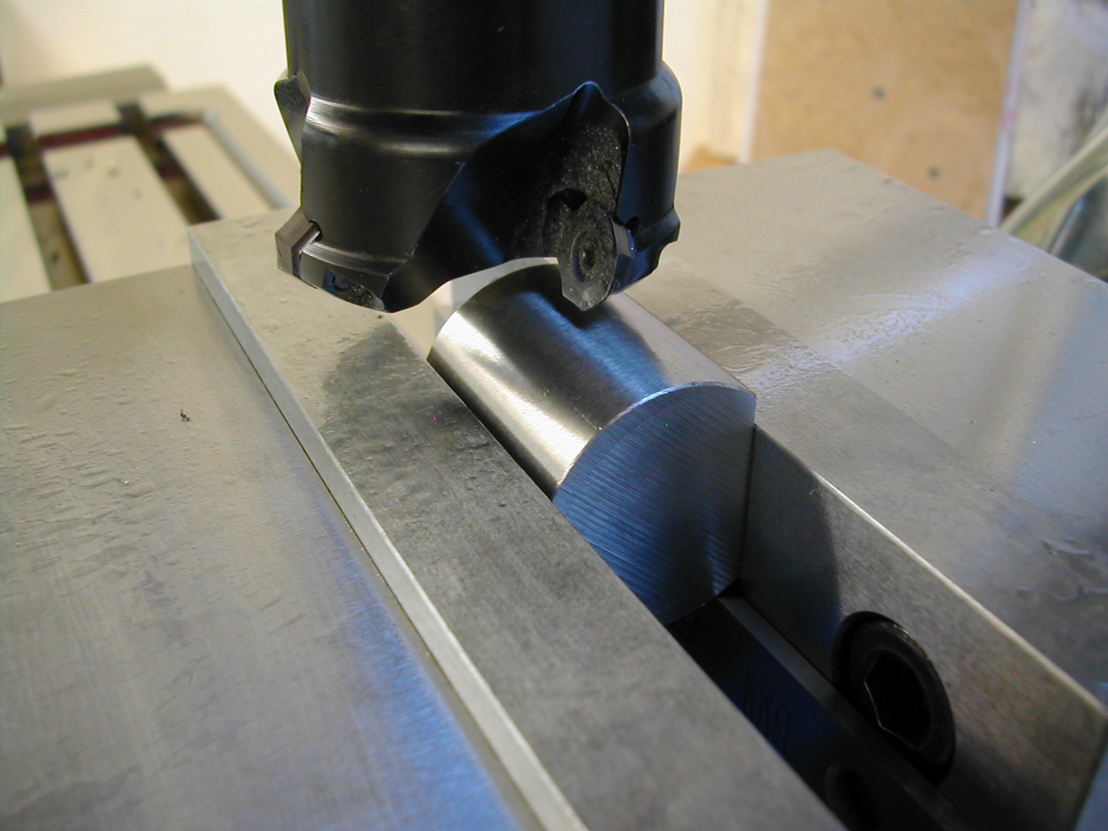
 For the next step, place the marked edge down and against the vise jaw, and take a skim cut to clean up the bottom. The bottom is now 90° to the front/back and 90° to the sides of the part as well. It is finished.
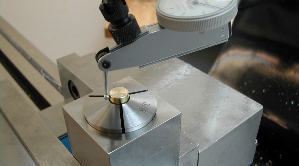
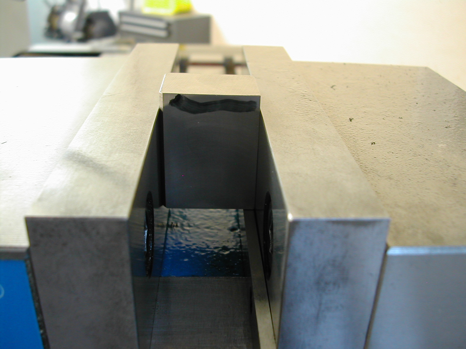
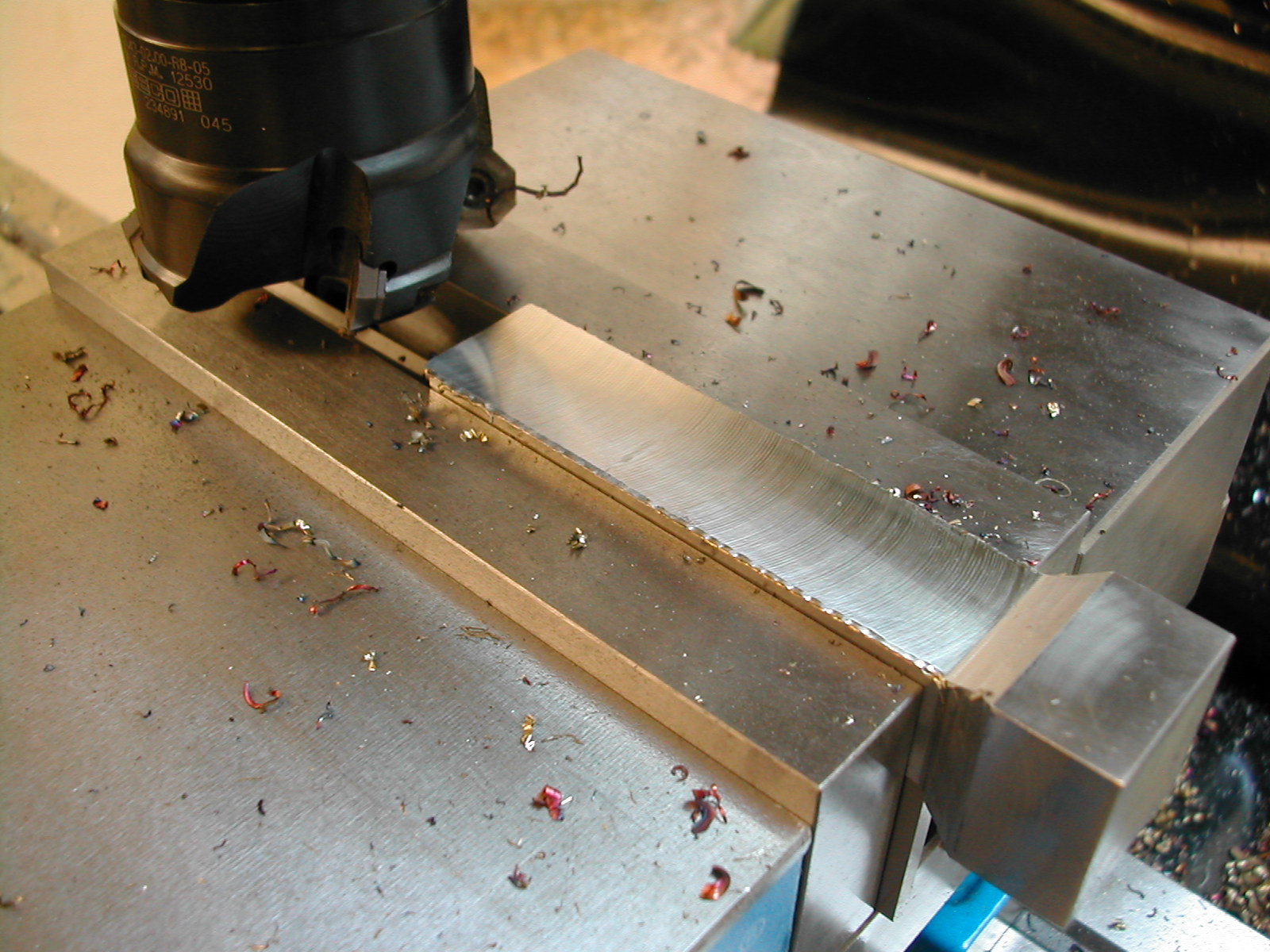
The last step is to flip the part over to the previously cut top, with the marked side against the vise jaw, re-cut the top to the finished dimension. After cutting, the top will now also be 90° to the front/back and 90° to the sides of the part. This last step is what is shown in the image.
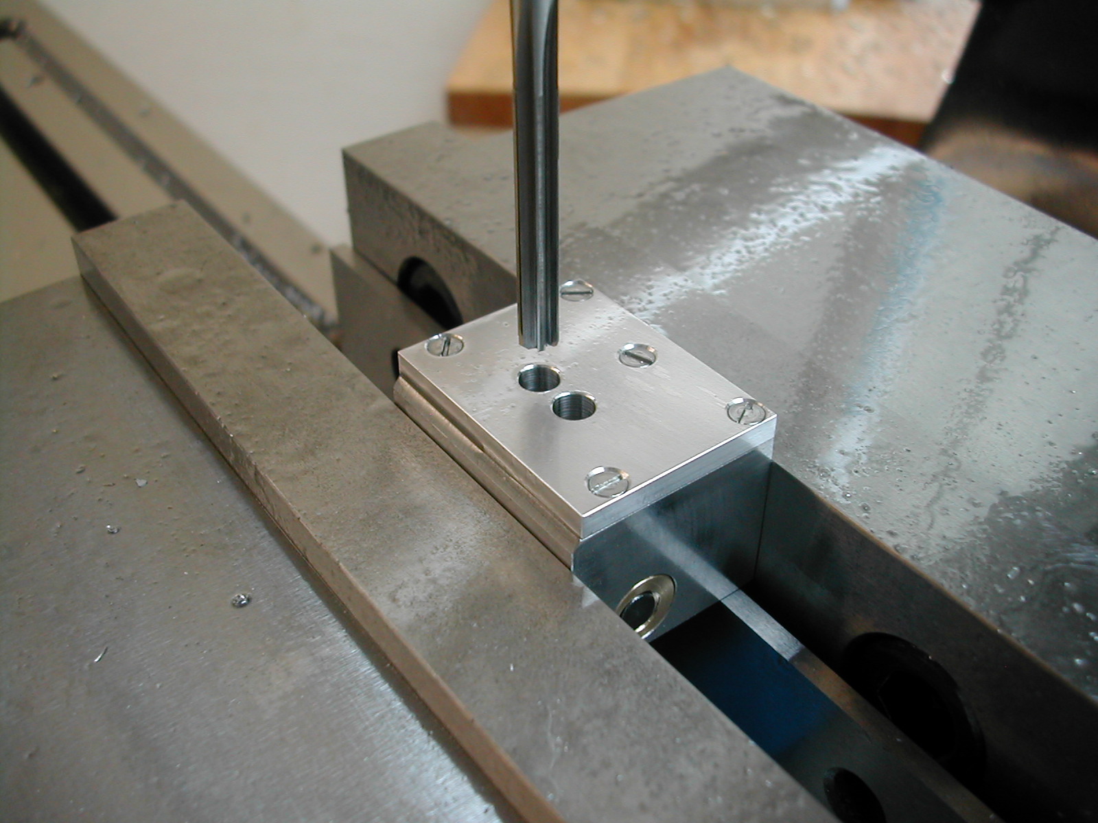
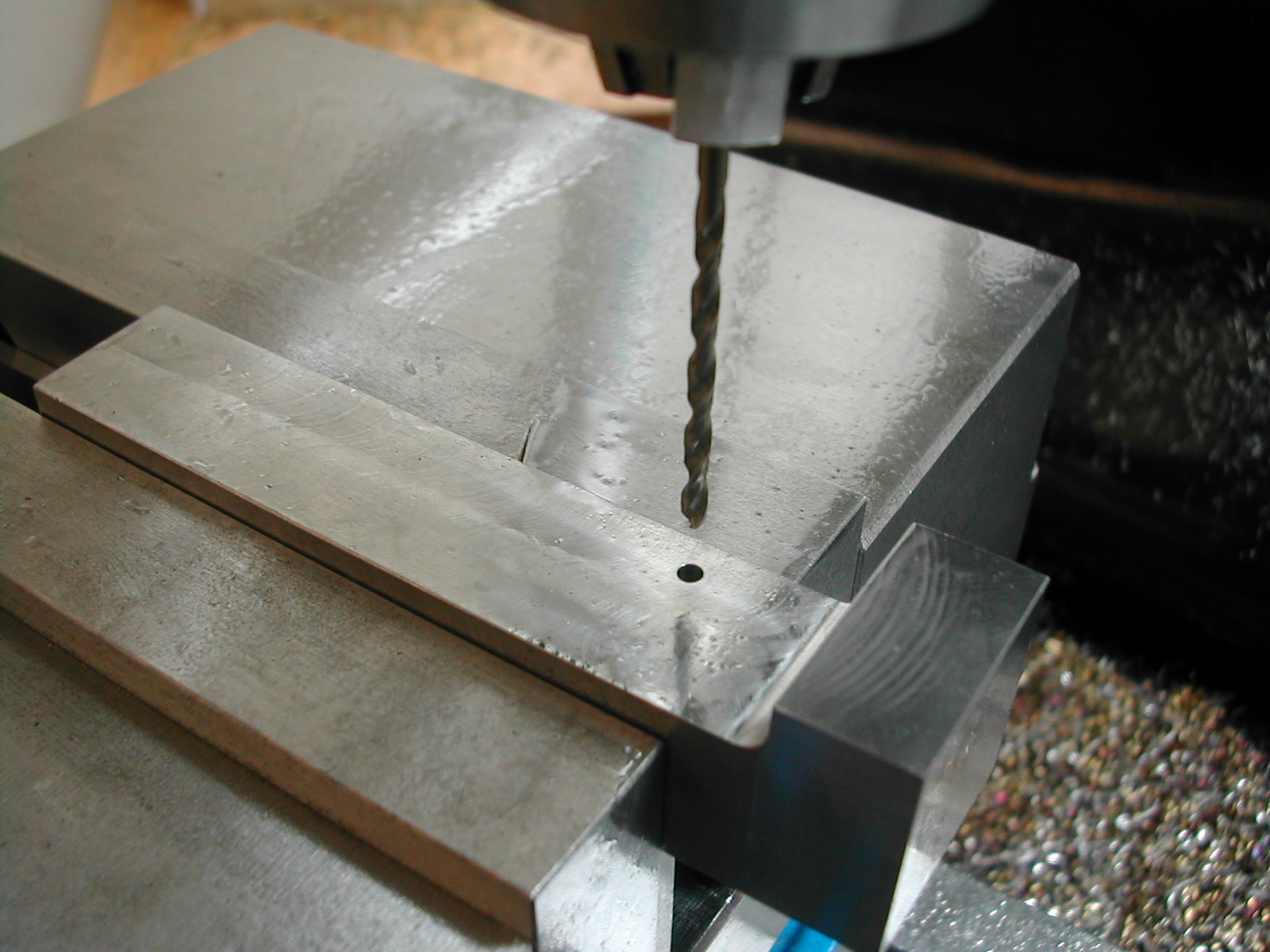
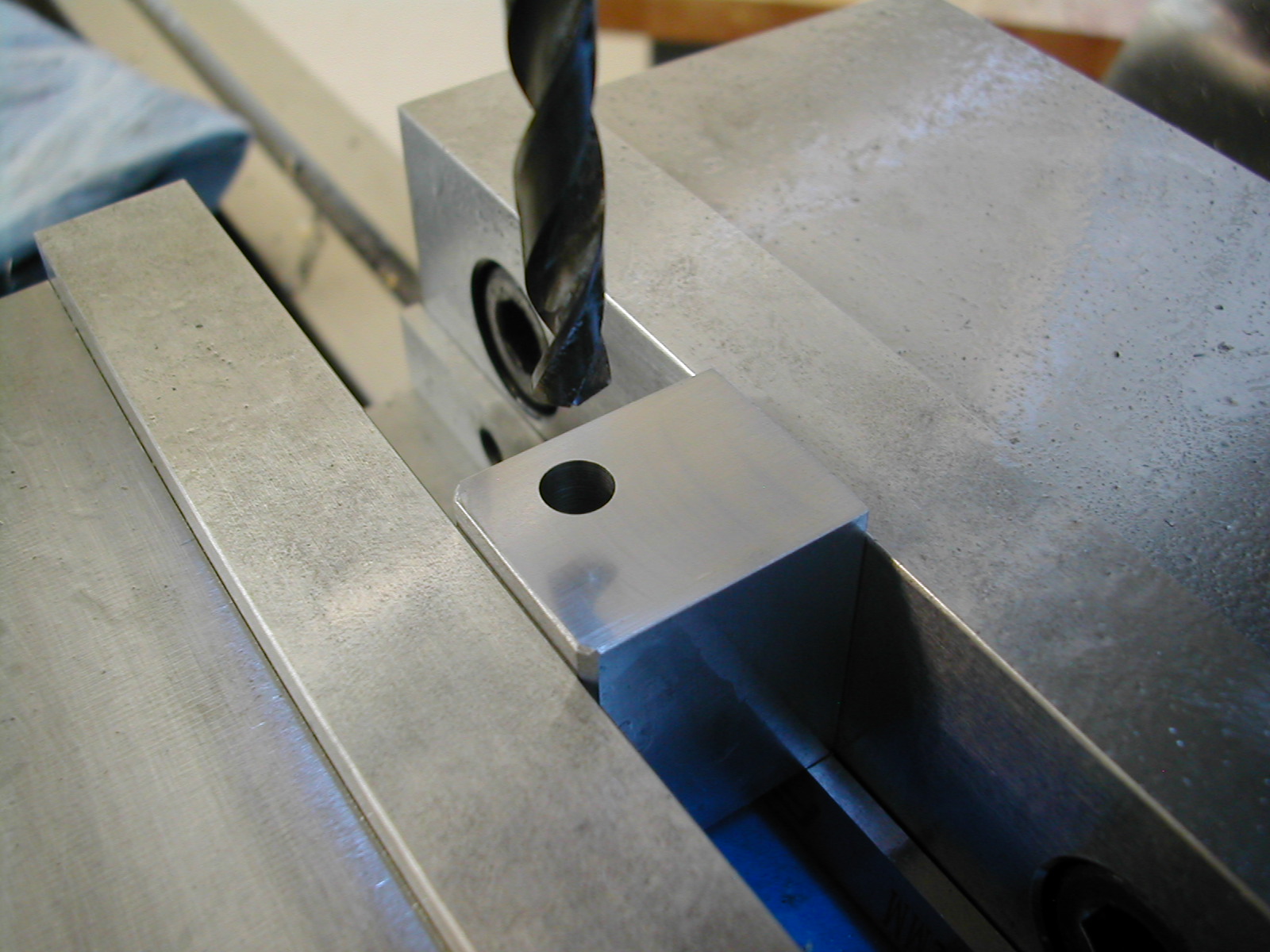 With the block to size, I’m drilling and reaming a 0.251″ hole for the split cotter clamp screw. This hole is offset 0.031″ from the cotter bores. I’m doing my cotters differently than Michael, so be sure to check the SolidWorks files if you are copying me.
 Since I have a nice tight machine, I’m plunging the cotter bore with a good 1/2″ endmill. Like I said earlier, it will be easy to fit the cotter OD to this bore and I haven’t had to knock myself out trying to get a good surface finish and a flat bottom hole with a boring head and bar.
 A quick chamfer and it’s time to flip the part and repeat, although you might want to put in the height adjust screw hole at this point as well.
 The next step is to place the #2-56 screw holes for the cover plate. I hate scribing and match-marking. Even if all you have are graduated dials on your machine, you can still place the holes more accurately and faster than scribing and punching.
 Michael used mild steel for his side plate. I had some 1/8″ thick 7075-T6 aluminum laying around and that should be more than hard enough to act as a bearing for the two small gears. So, I’ve machined one long edge and I’m cutting both short sides to bring it to length. I’m not going to worry about the overall width of the part as the other long edge will be cut when I do the dovetail slide.
 The tricky part is to remember to reference the long side that has been cut when placing the countersinks for the #2 screws.
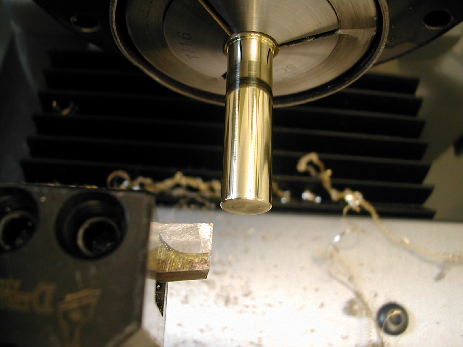 Before I can go any further on the tool holder head, I need to make the split cotters so they can be cut at the same time as the spindle housing bores in the head. So, I’m turning down a section of brass rod to make the two cotters. I’ll need about an inch total for both cotters. Once the OD is turned, face and chamfer the end and hacksaw off a section slightly longer than the finished top cotter length plus 0.025″ plus and additional 1/28″. This extra 1/28″ is so we can later adjust the final position of the clamp screw handle up to one full turn, and the extra 0.025″ is to hold it in the correct position for machining in the tool holder head.
Face off and chamfer the end again, and hacksaw off a piece long enough for the bottom cotter plus 0.025″.
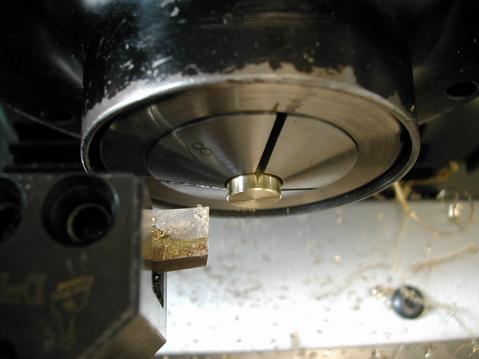 Flip each piece around and face and chamfer the sawn ends of each cotter to the finished dimensions plus the additional allowances.
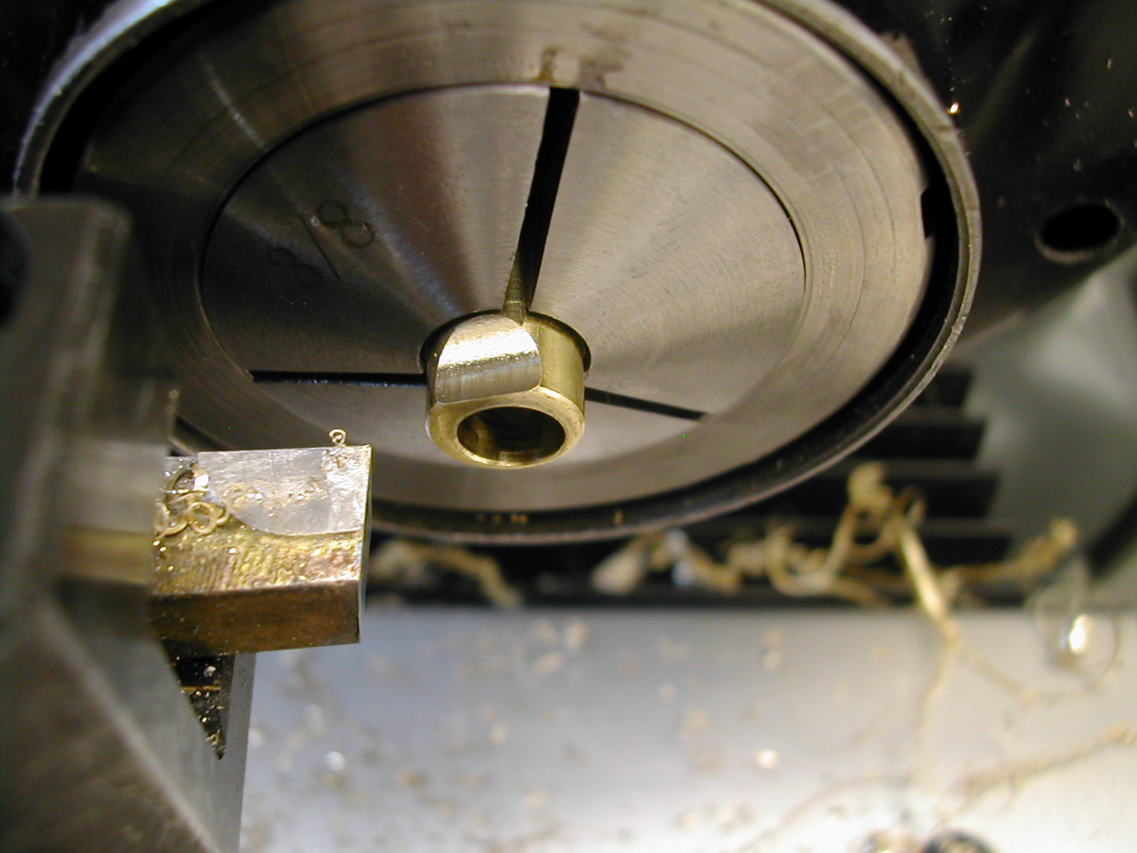
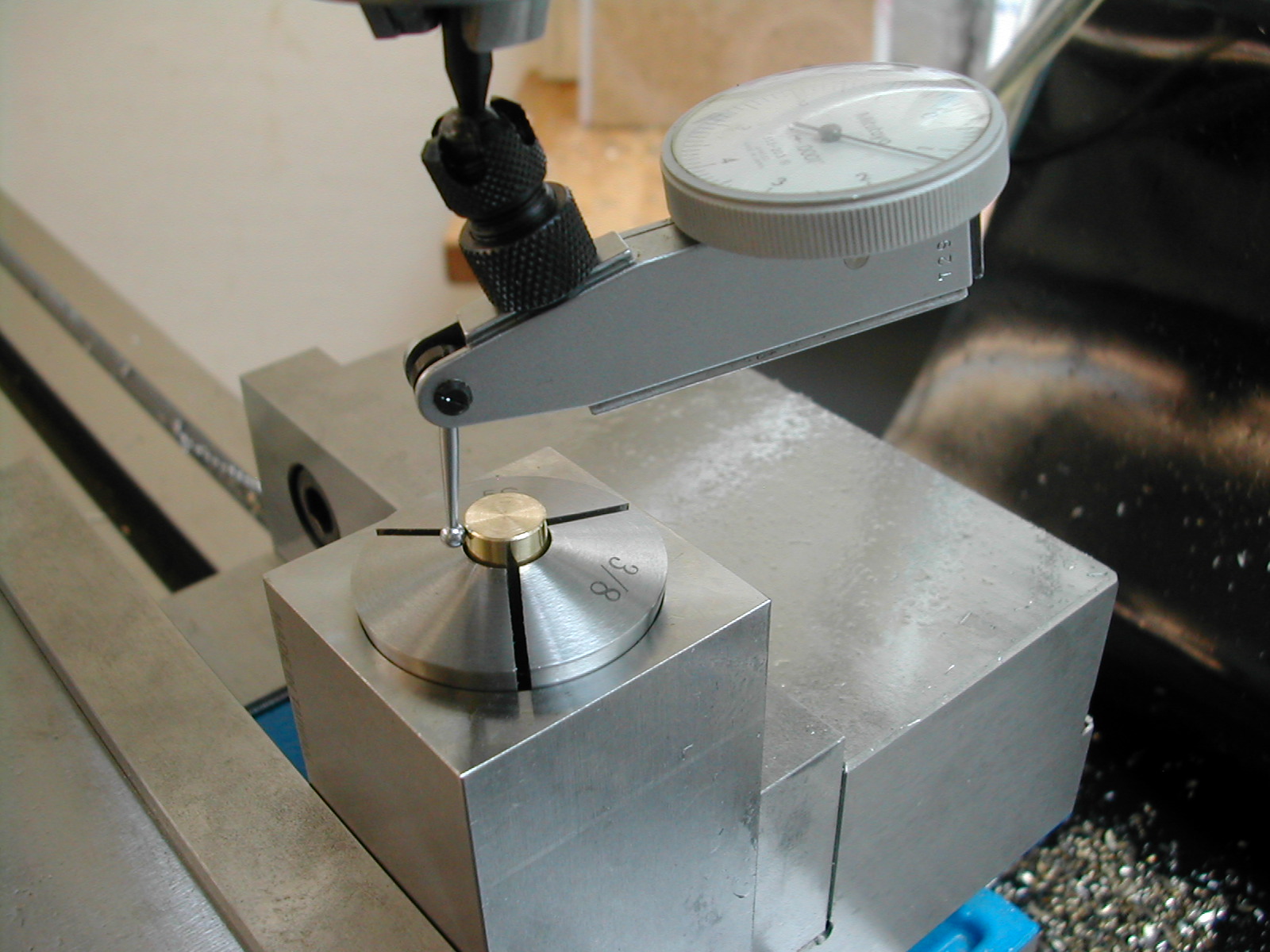 With the bottom cotter held in a collet, indicate the OD to locate the center of the cotter.
 Offset 0.031″ to any side and drill and tap for the 1/4-28 clamp screw. Repeat the process for the top cotter, but ream it 0.251″.
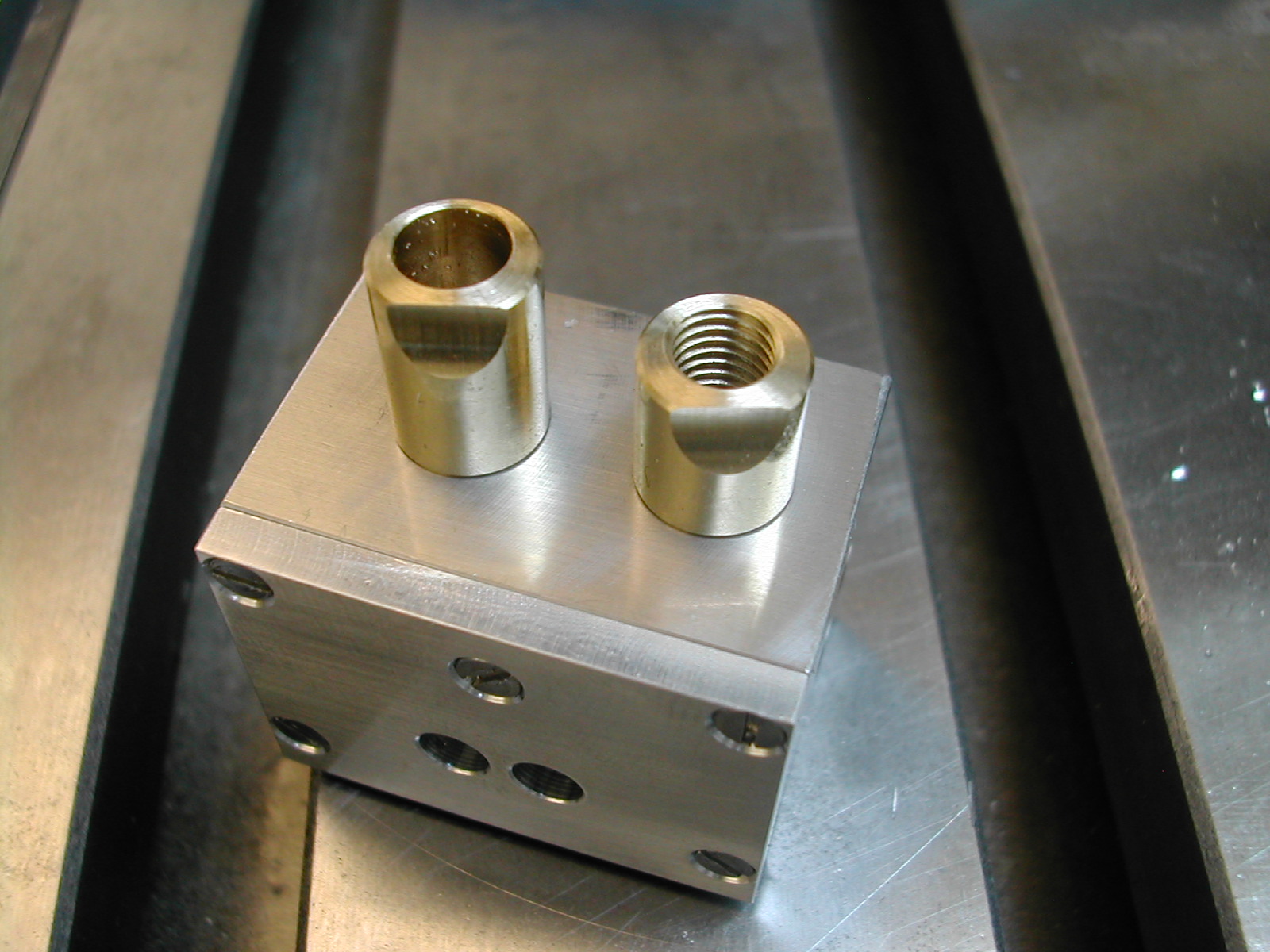
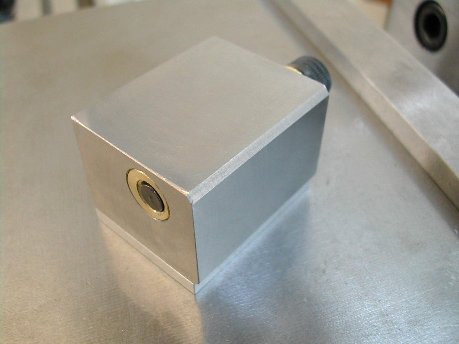 The two cotter can now be temporarily installed in the tool holder using a suitable 1/4-28 bolt. The bottom cotter should be flush with the bottom of the tool holder head while the top cotter will be proud.
 Temporarily attach the cover plate, and indicate the tool holder block in the vise. Drill and ream the 3/16″ holes for the small gears. My small gear holes were moved slightly from Michael’s positions because I’m going to use some pre-made pinion stock instead of cutting my own gears. Check the SolidWorks model if you are copying me for the new location of small gear holes.
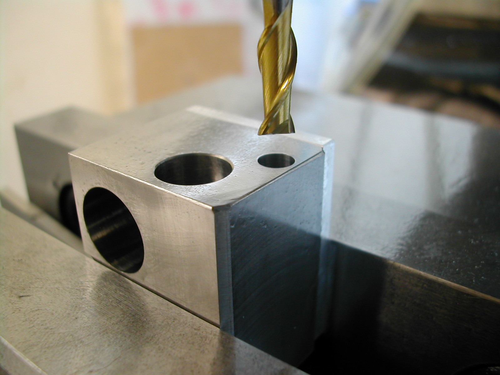
 Remove the cover plate without removing the head from the vise, and drill and ream the two 0.500″ holes for the spindle housings.
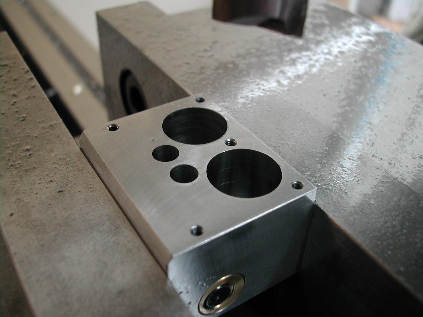
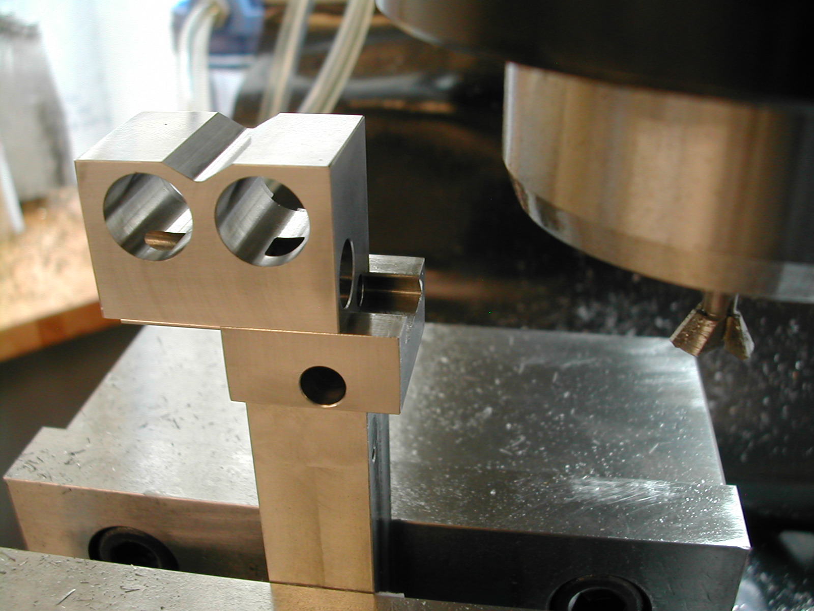
 And finally add the gear counterbores. Since the pre-made pinion stock I’m using has a different DP and number of teeth from Michael’s, my counterbores are slightly different diameters.
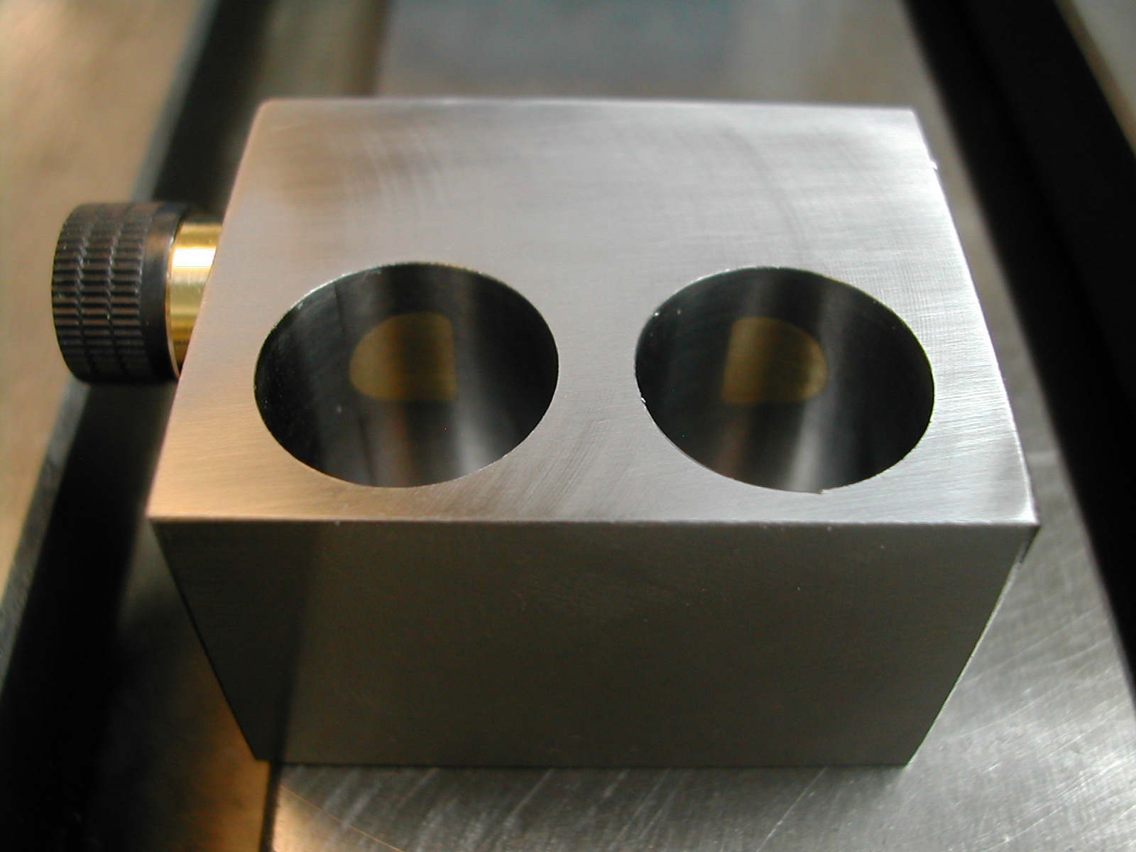 If this were a better photo, you could see how nicely the cotters match the bores since they were cut at the same time.
 The last step to finish the cotters is to remove the extra 0.025″ from the ends with the cove cut. Don’t cut the wrong ends!
 Here are the finished albeit rather dirty cotters. Set these aside for now we won’t need them again until the final assembly. You can also re-attach the cover plate on the housing at this point.
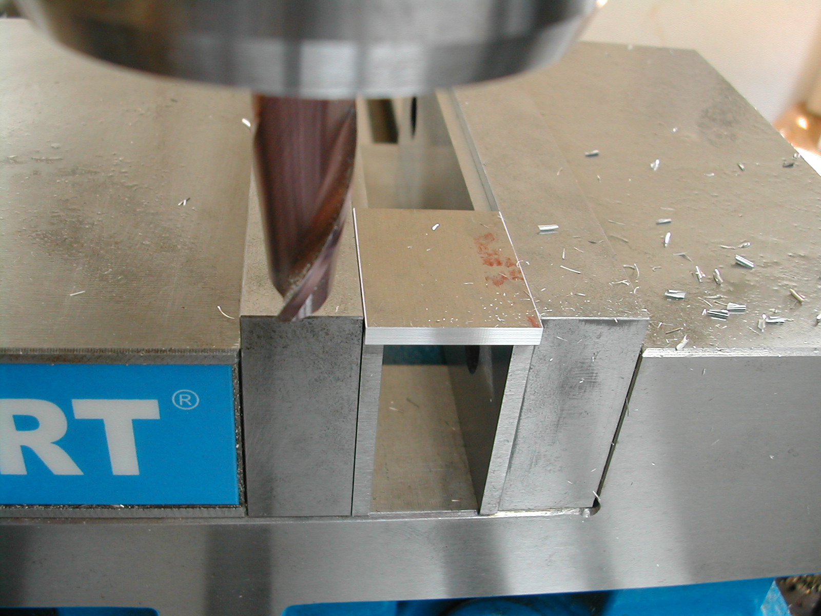
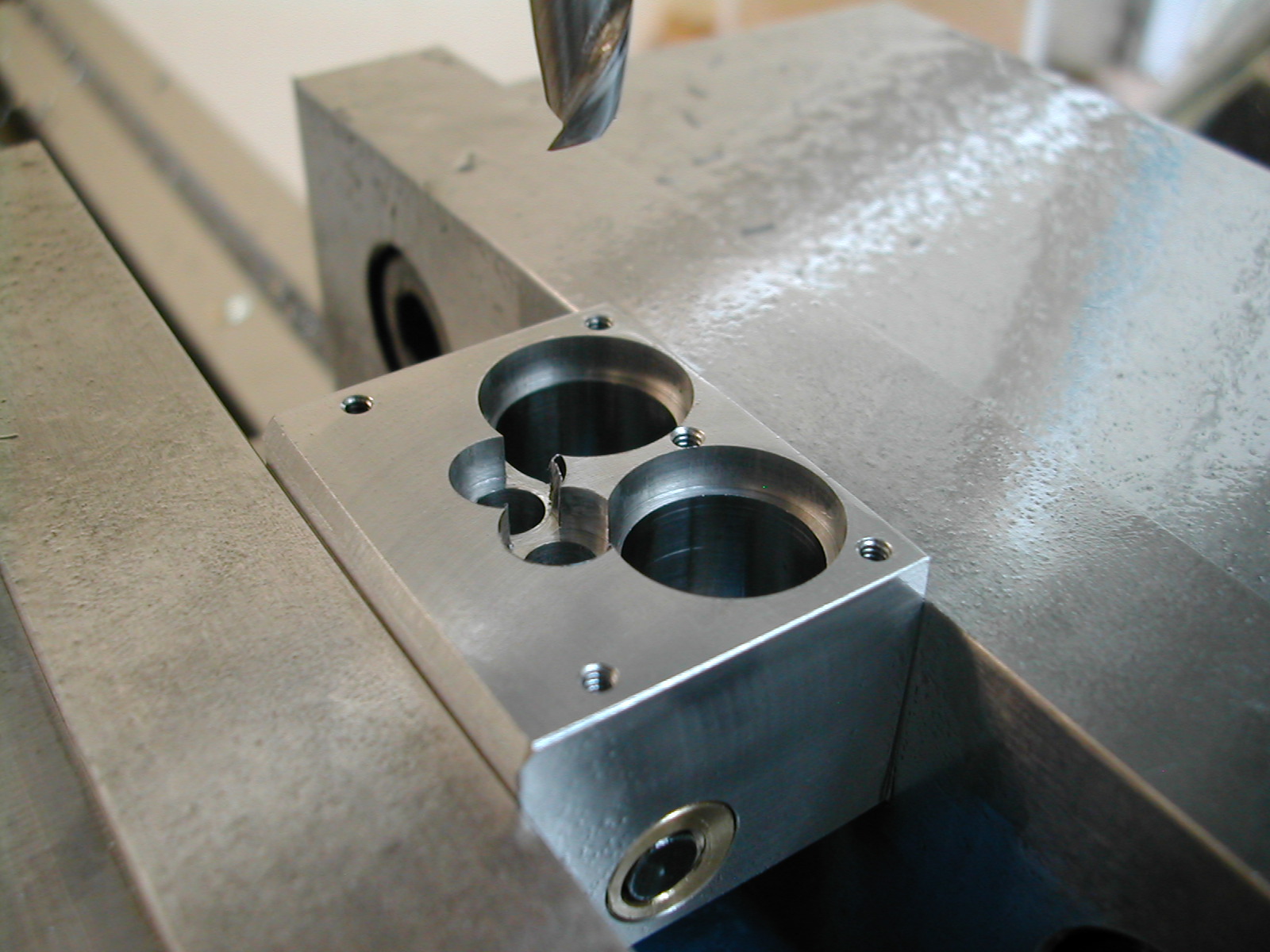
 Here I’m running the ballnose cutter through to prepare for the clearance cuts on the front of the housing. This goes down the centerline of the part.
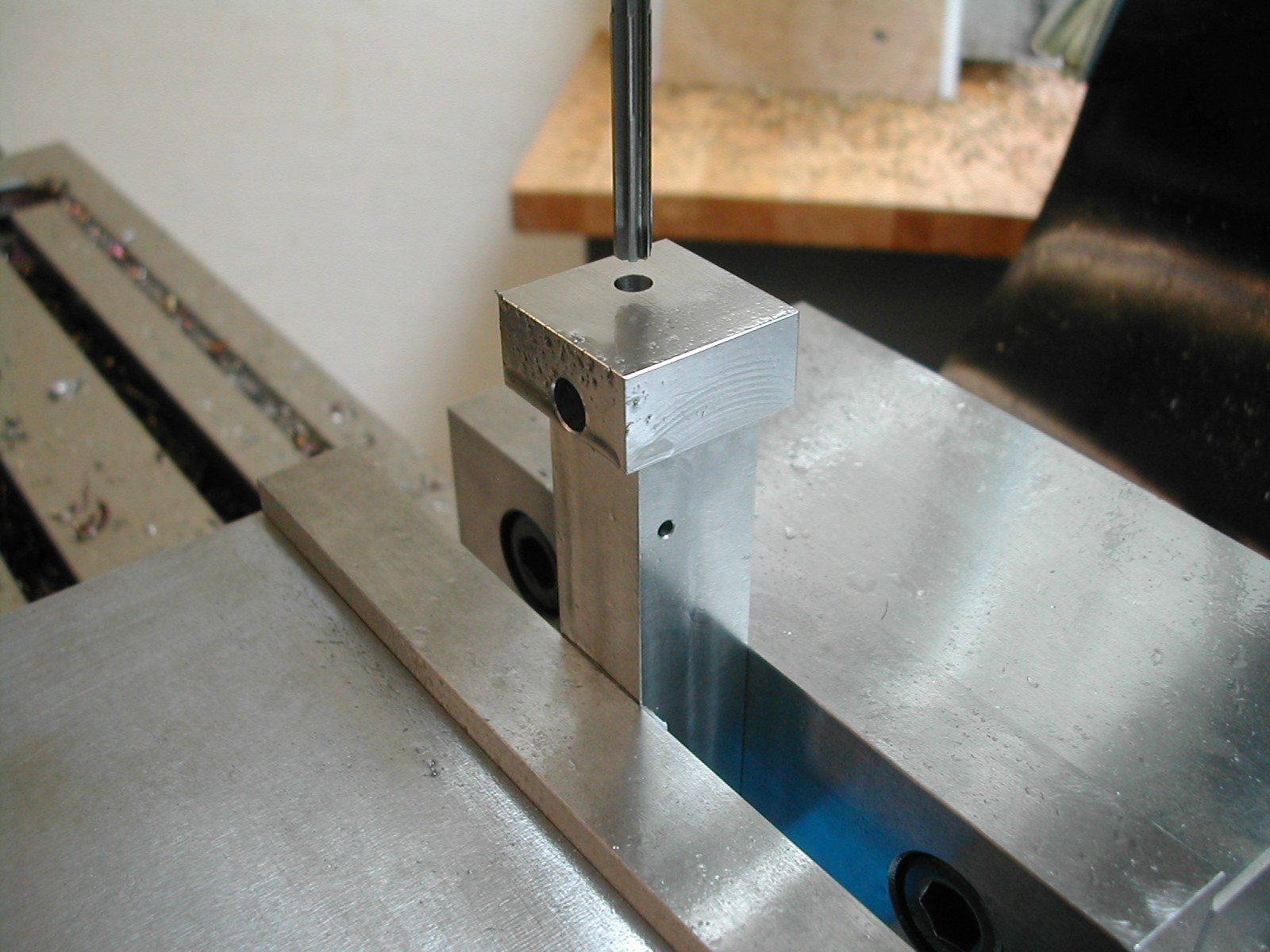
 Oops. Time to put in the height adjust screw hole that I forgot earlier. If I would have done this when I put in the top cotter, I could have saved myself having to re-indicate in the block.
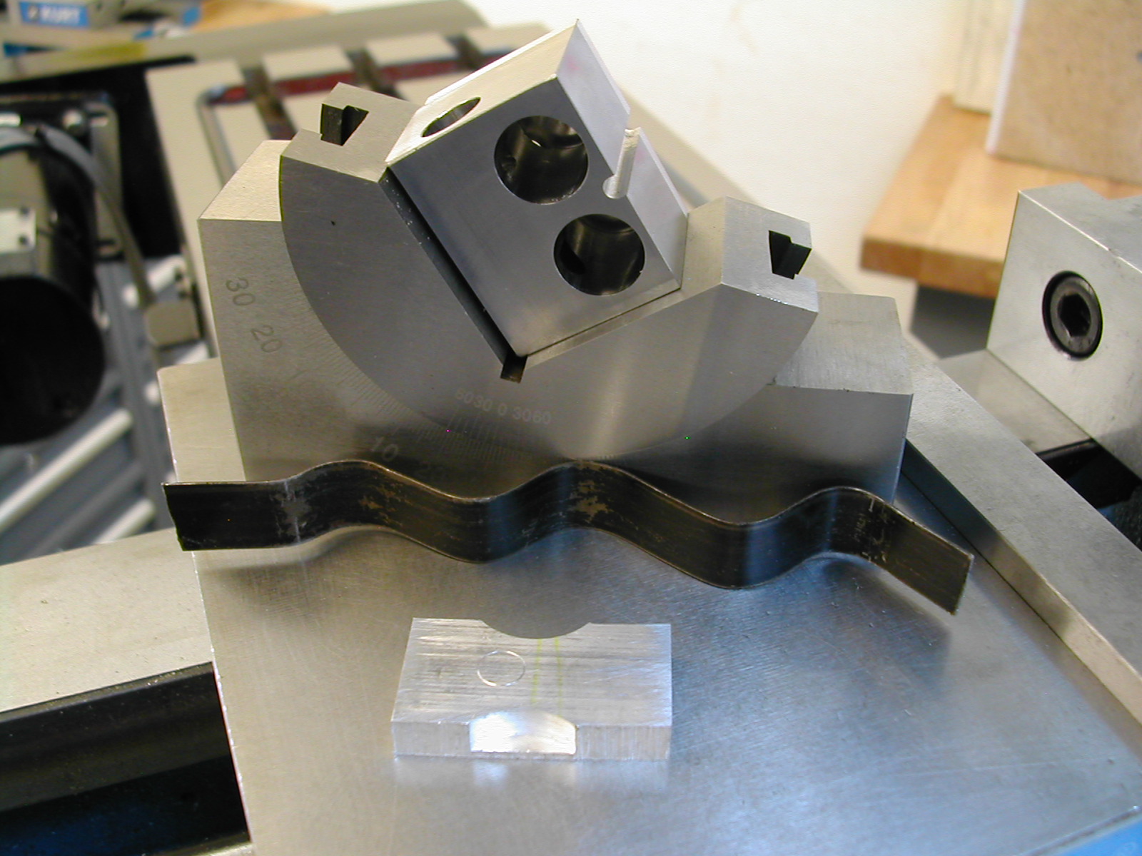 This is the setup I’m going to use to make the face clearance cuts. I’m using a wavy piece of pallet strapping material to act as a spring to hold the angle block in position in the vise while I loosen the vise to flip the part.
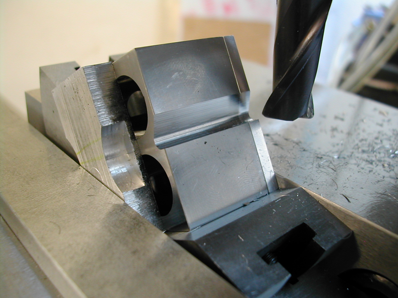 Here’s the first cut. Work slowly to get the height and depth correct to just kiss the tangent of the earlier ballnose cut. The scrap aluminum block is there because the part is narrower than my angle block.
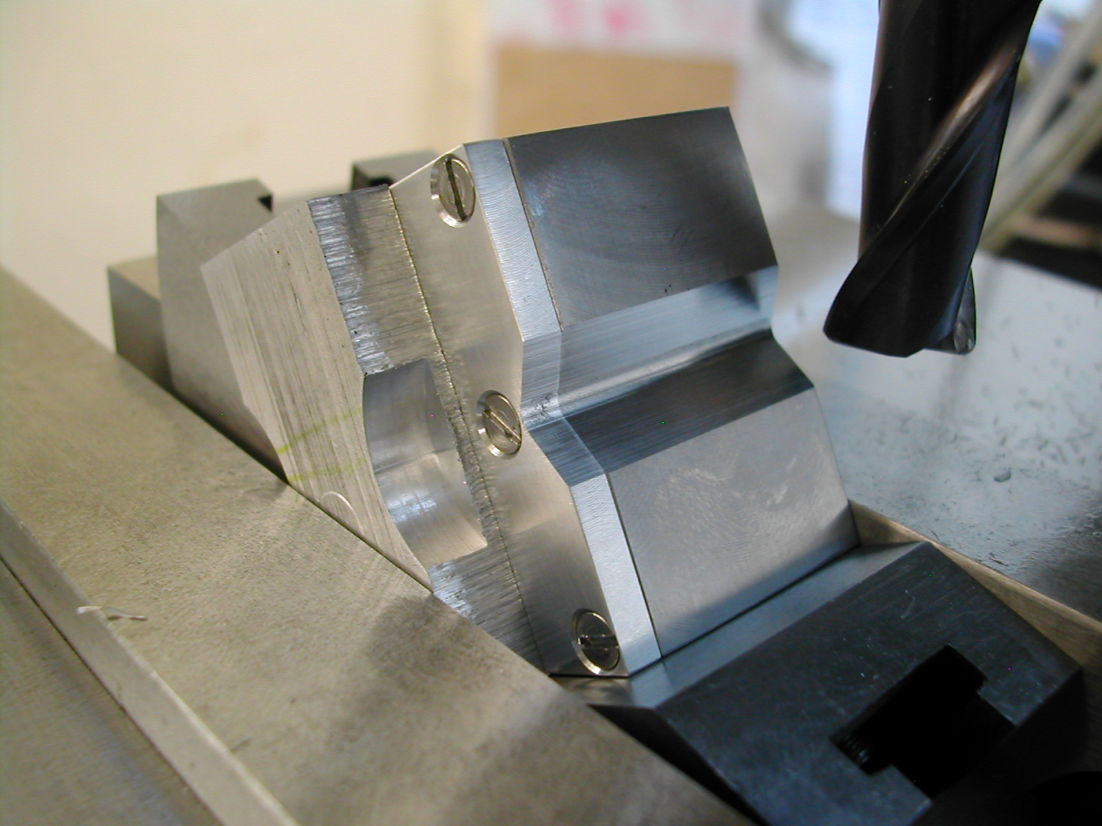 With the first cut made and the spring holding the angle block in place, it’s a simple matter to loosen the vise and flip the part. If you made the ballnose cut earlier at the centerline of the part, you can make this cut at the same settings as the last.
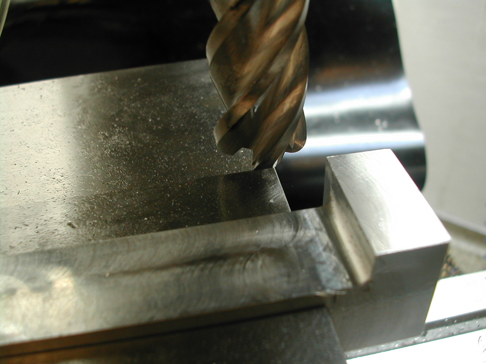
 It’s time to work on the dovetail. Now you see why it wasn’t critical to cut the second side of the aluminum cover earlier. We’re cleaning it up now while removing the bulk of the dovetail material with a regular endmill. This cut is a few thousands shallow on the bottom but to-size on the width. The width is sized to leave a 0.010″ flat on the finished dovetail.
 Here I’m checking the finished dovetail across pins and you can see the flat at the top. I’ll need to file this flat into a radius since my dovetail cutter leaves a 1/64″ radius.
 With the dovetail finished, it’s time to cut the clearance groove for the height adjust screw and nut.
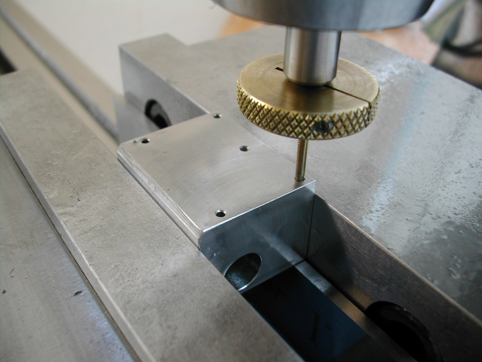
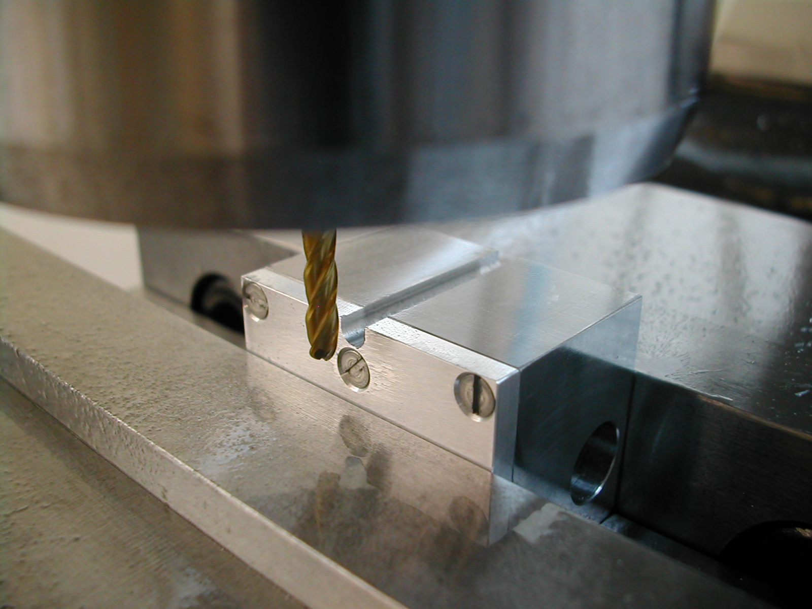
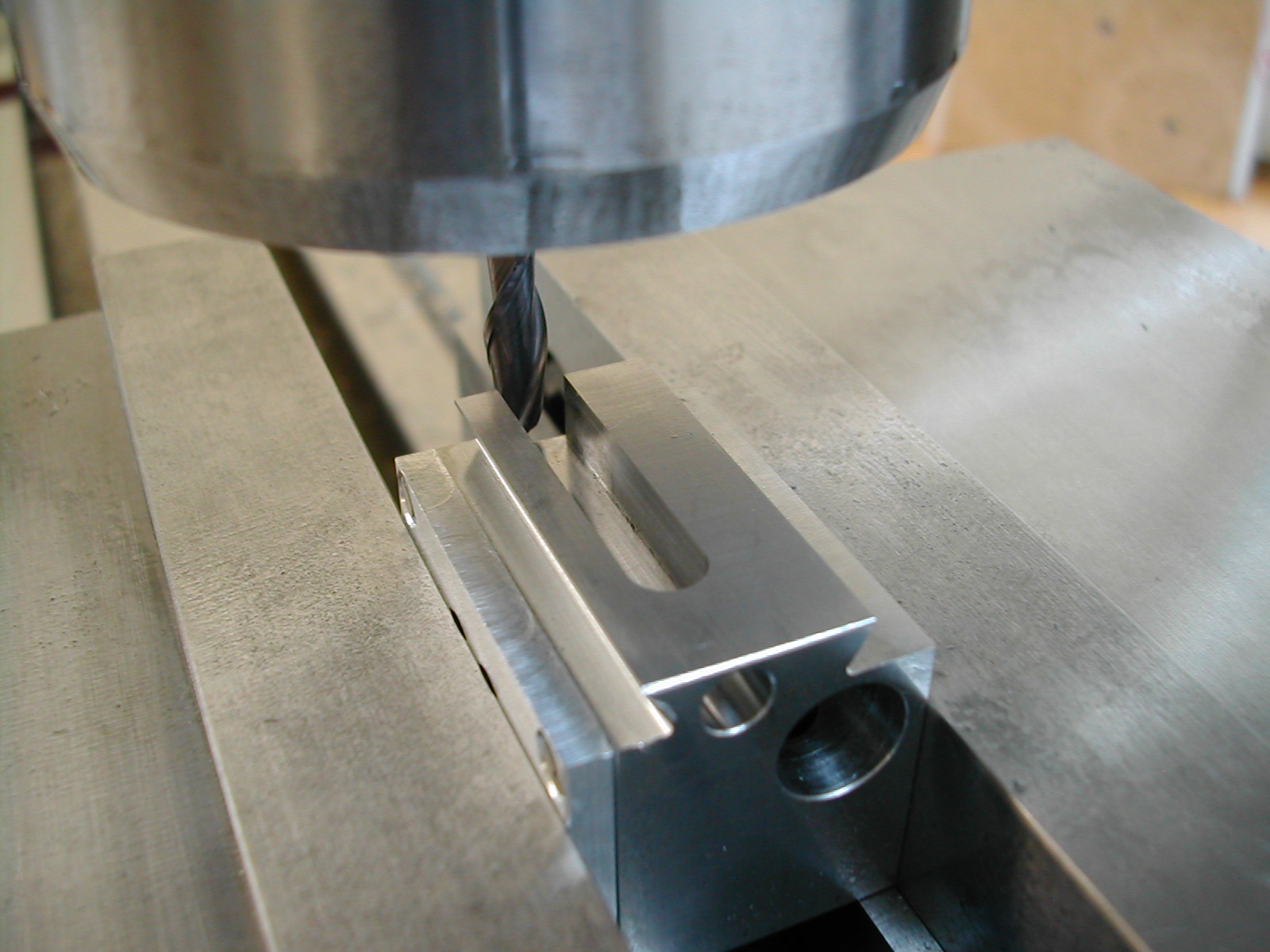
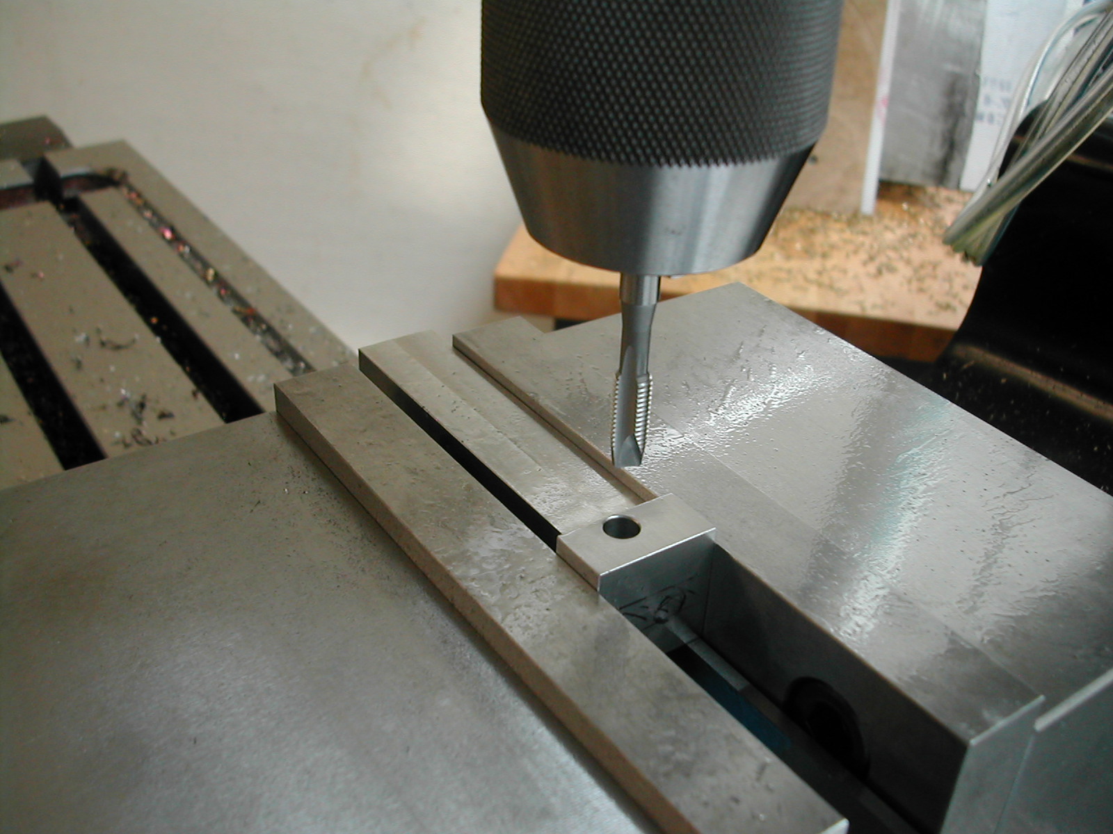
 The last step on the head is the #3-48 tapped hole for the height adjust bushing. I’m spot facing the area with a 7/64″ endmill to get a flat surface on which to drill.
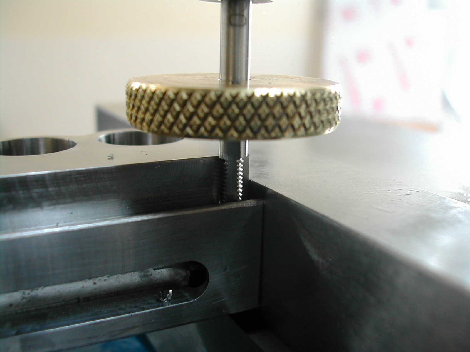 I barely had enough thread length on my tap to get this hole done. Its not fully tapped, but the set screw stops about 0.010″ inside the hole. That should be enough to retain the brass height screw bearing.
 With the head complete, it’s time to start on detail 06, the Tool Holder Arm. Once again, I’m making squares out of rounds.
 I’m using my face mill to rough out the side cuts as well. My version of the Tool Holder Arm has the side cuts only on the top and front side. This keeps the bottom and back flush with the toolholder groove. I also bumped up the thickness to 3/4″ since that would easily fit in my toolholders and would be significantly stiffer if I ever needed to extend it for any reason.
 The next step is to face off the end of the arm, and make the finish cuts with the 0.125″ radius on the two sides.
 And finally the finish cut to the overall length on the other end. You can really see how nice this pre-heattreated material cuts!
 The next step is to drill, tap, and counterbore for the 1/4-28 height adjust clamp screw.
 I’ve added a 3/32″ stop drill for the clamp slot we’ll me making in a few minutes. Probably not needed since fatigue won’t be a problem here, but its a best practice and I think it adds a nice touch.
 Next is the drill and ream for the height adjustment nut and this leaves us in position to make the dovetail cuts.
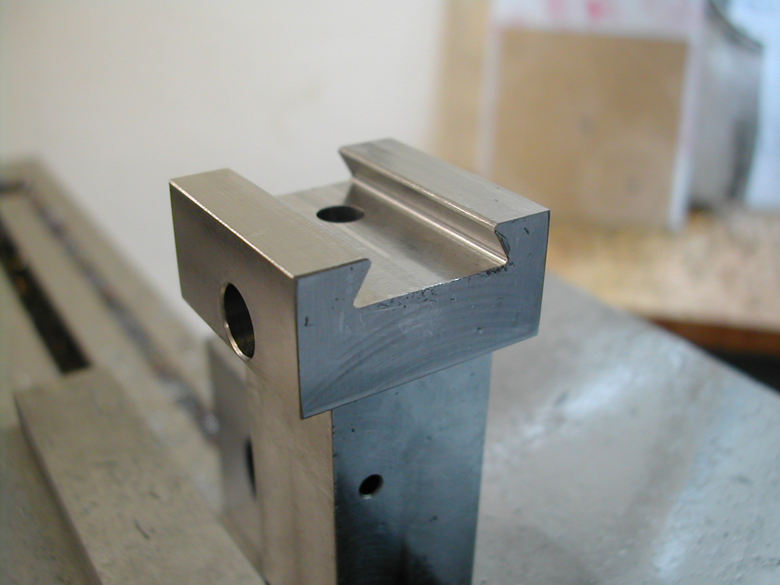 I seem to have lost my photos of the dovetail cutting, but here is the finished part. I followed the same process as the head starting with cleaning out the bulk of the material with a regular endmill. Shallow on depth but to width. This was followed with the dovetail cutter at the finish depth however my finish depth for this dovetail was not the same as the other side. I added 0.004″ additional clearance since I don’t think both sides of a dovetail should make contact. Have a look at the dovetail ways on your machines for reference.
Again, I needed to file the flat sides into a radius to provide clearance for the mating part.
 Here you can see the two parts mated together. At this point light pressure was required to slide the dovetail.
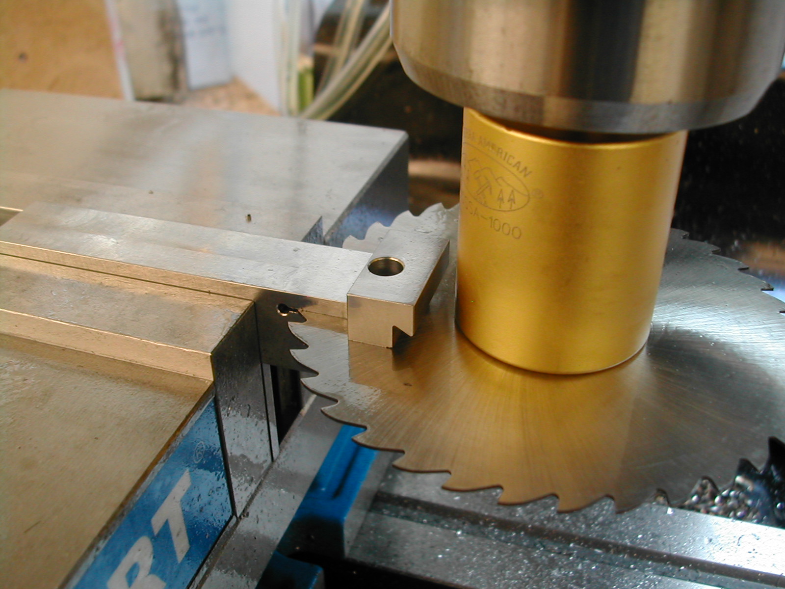 The last operation on the tool holder arm was the clamp slit made with a 1/32″ slitting saw. After this cut, the dovetail closed up and was a very tight fit. I drove a wedge into the end to spring back open. I went a little past the light sliding fit I had earlier to a slightly loose fit, but the clamp screw will bring this back and the geometry is correct.
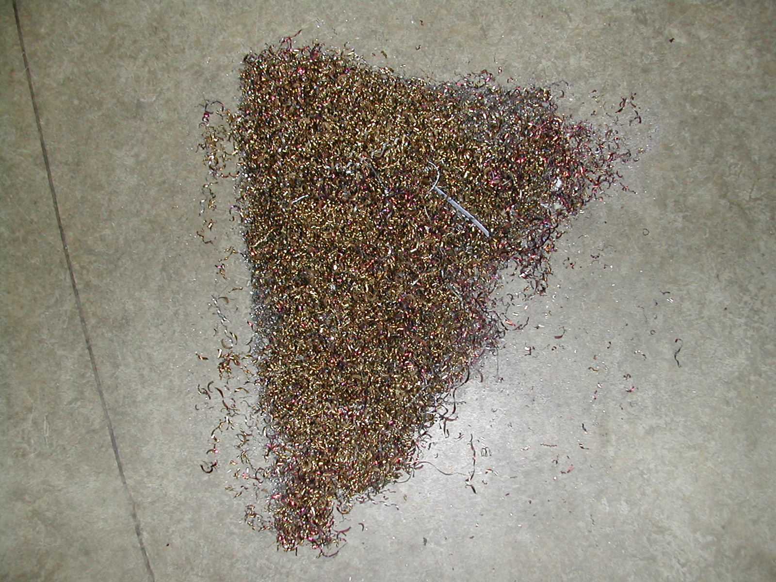 And for a parting shot, here’s the pile of chips after Day 1.
Disclaimer and License
All material, including the CAD drawings, relating to the construction of the Cut Knurling Tool presented on this site is free to use any way you see fit. However, no guarantees are made regarding the accuracy or correctness of the material presented here.
Downloads
(CAD drawings are in SolidWorks 2013 Format)