
Detail 02, the Spindle Housing
 Since I started the Spindle Housings while working on the gears, it was time to finish them. I started by constructing my tooling block to hold the housings while machining the business end. I’m not a big fan of layout fluid, scribing, and center punching so all of my machining was done in the mill using an edge finder and DRO for positioning.
Here I’m using an indicator to set the 60° angle. A little trig and a little tapping and I ended up with 59.96°. I needed this pretty close since I was going to be working off of CAD calculated dimensions.
 When I squared this block up, I purposefully did not break the front edge so that I could use an edge finder to locate it fairly accurately. Once I locate the sharp corner, I machined off 0.100″ to give a square face to locate from in the future.
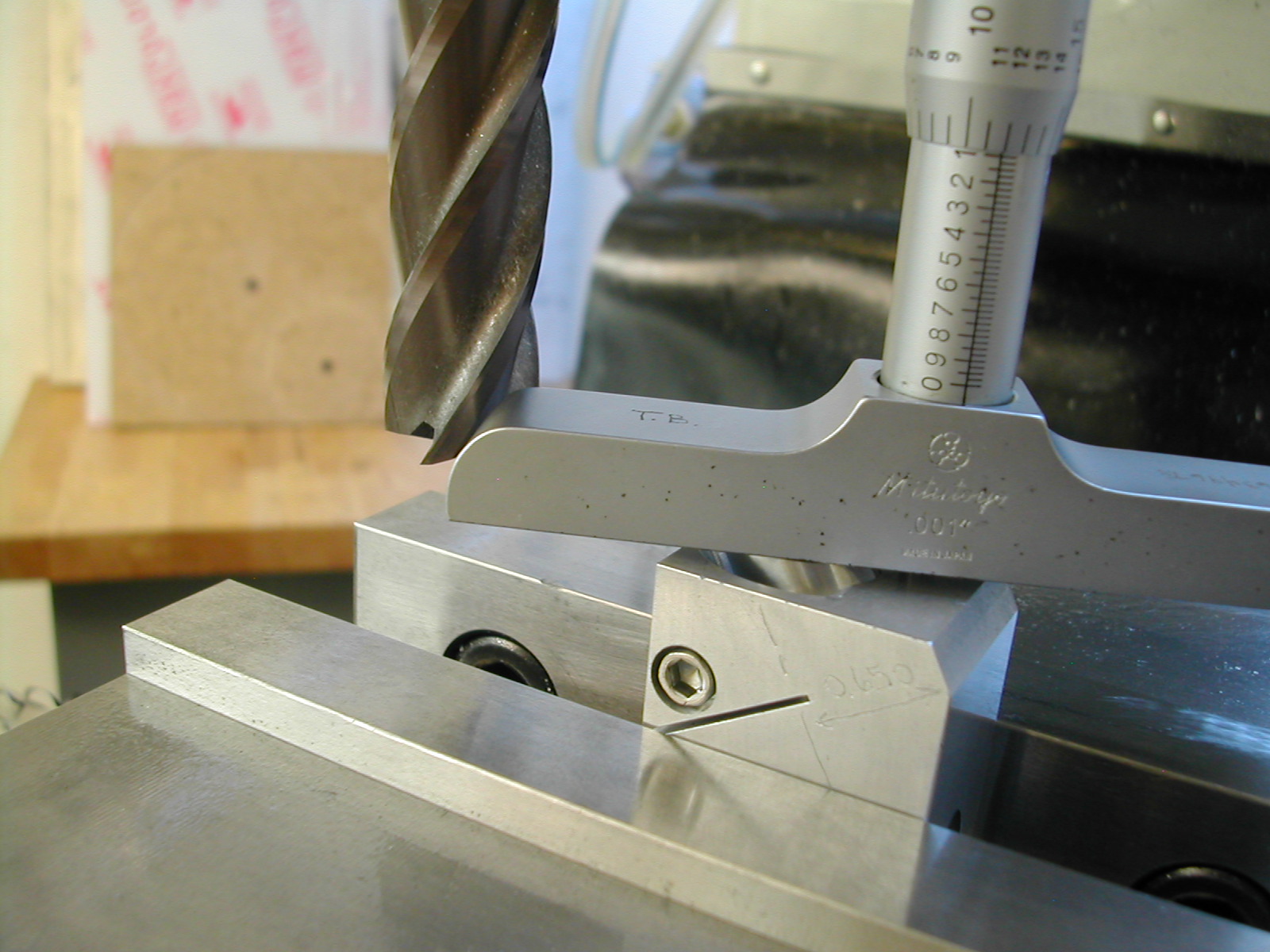
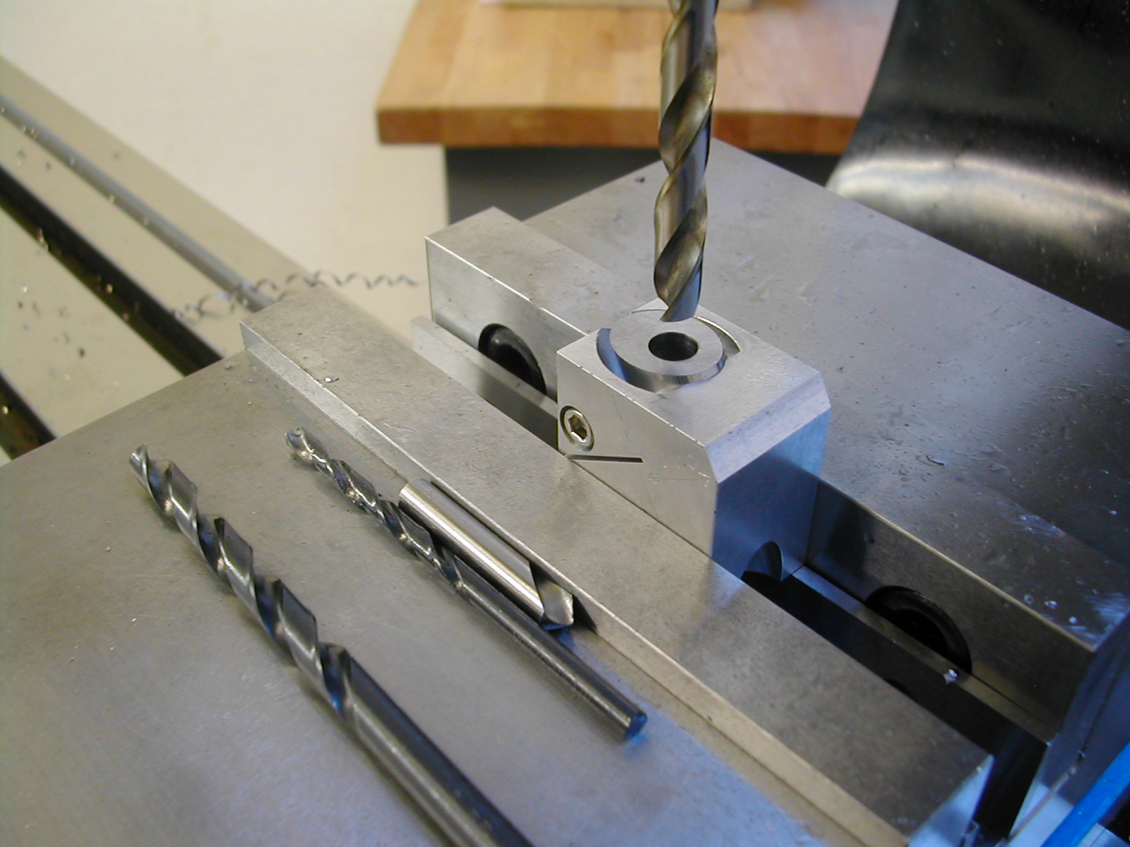
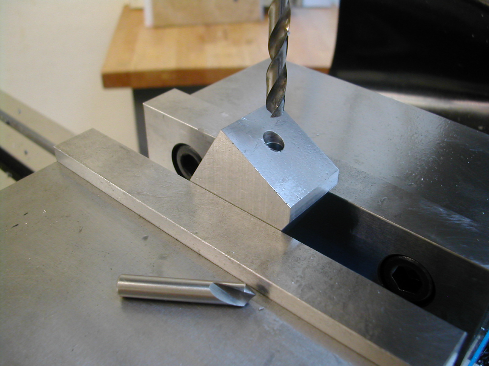 With 0.100″ machined off, the centerline for the bores is 0.650″ back from the machined surface. I had a 1/4″ spotting drill so I started with that and followed with a 15/64″ drill through.
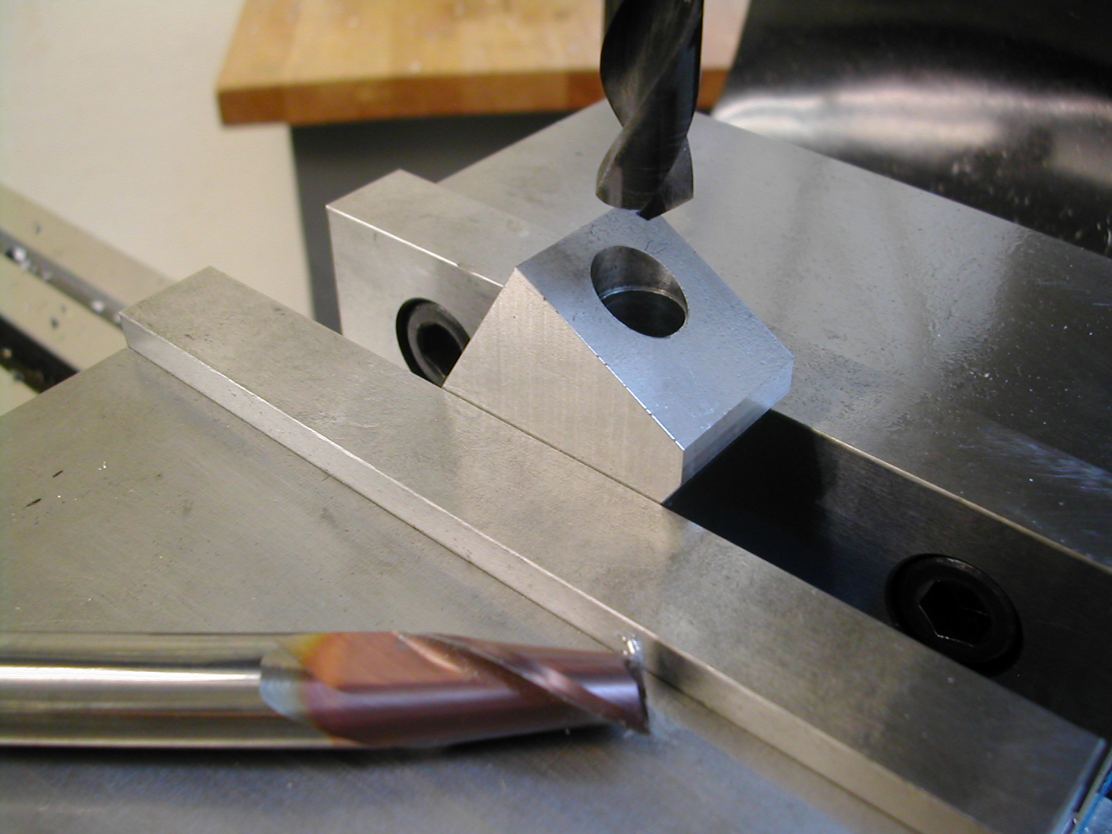 With the center cleared away, I counterbored with a 1/2″ endmill to get a flat surface to follow through with a 31/64″ drill.
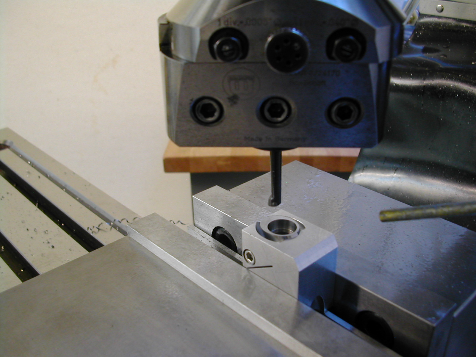
 My boring head made quick work opening this up to 0.0005″ over the OD of the Spindle Housings. I checked both housings at this point to make sure both would fit with finger pressure.
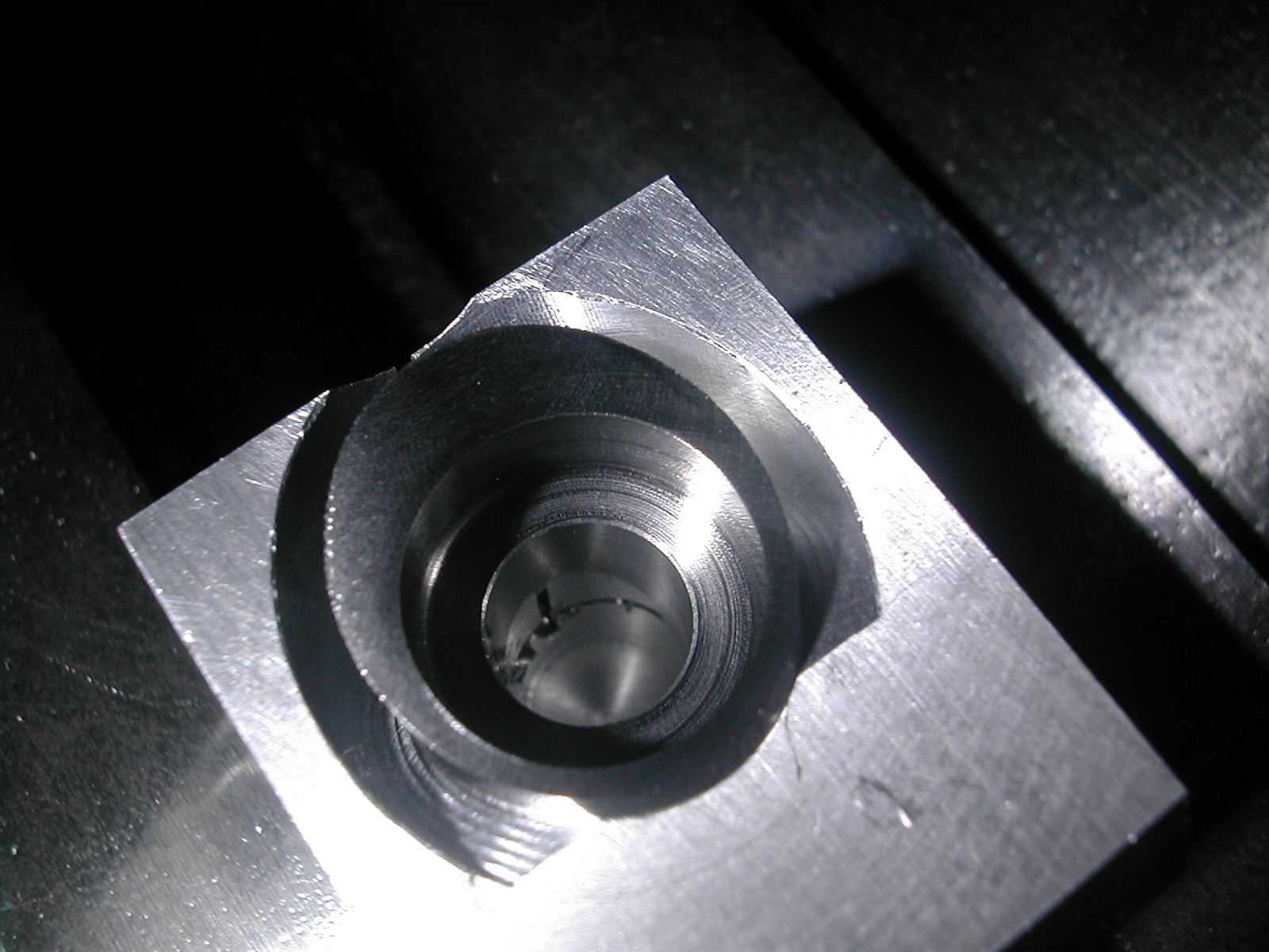
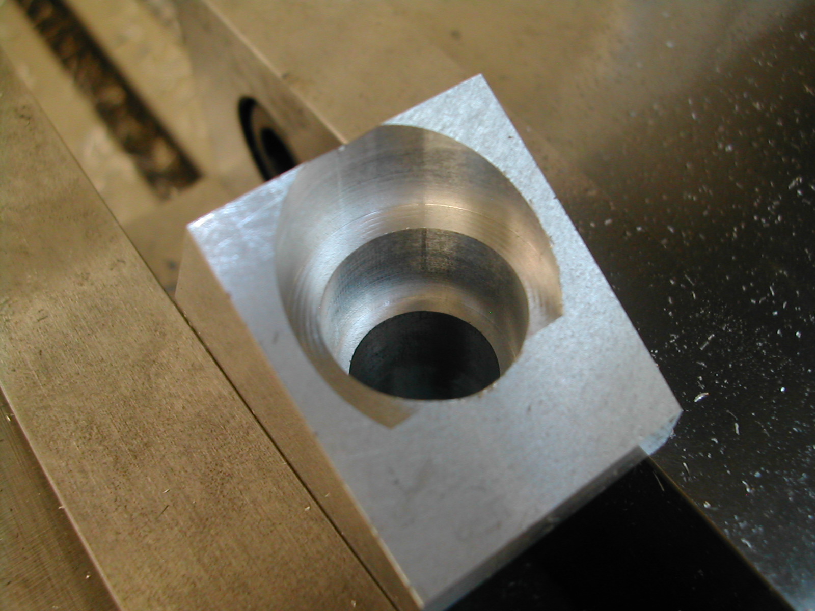 With the 1/2″ bore finished, I opened up the 13/16″ clearance area 0.375″ down from the sharp back corner, and then made a close fit ø0.615″ bore 0.750″ total down from the sharp back corner. The ø0.615″ bore needed to be a close fit to the Spindle Housings as well since this is the clamping surface. Be sure and check both Spindle Housings in the fixture at this point.
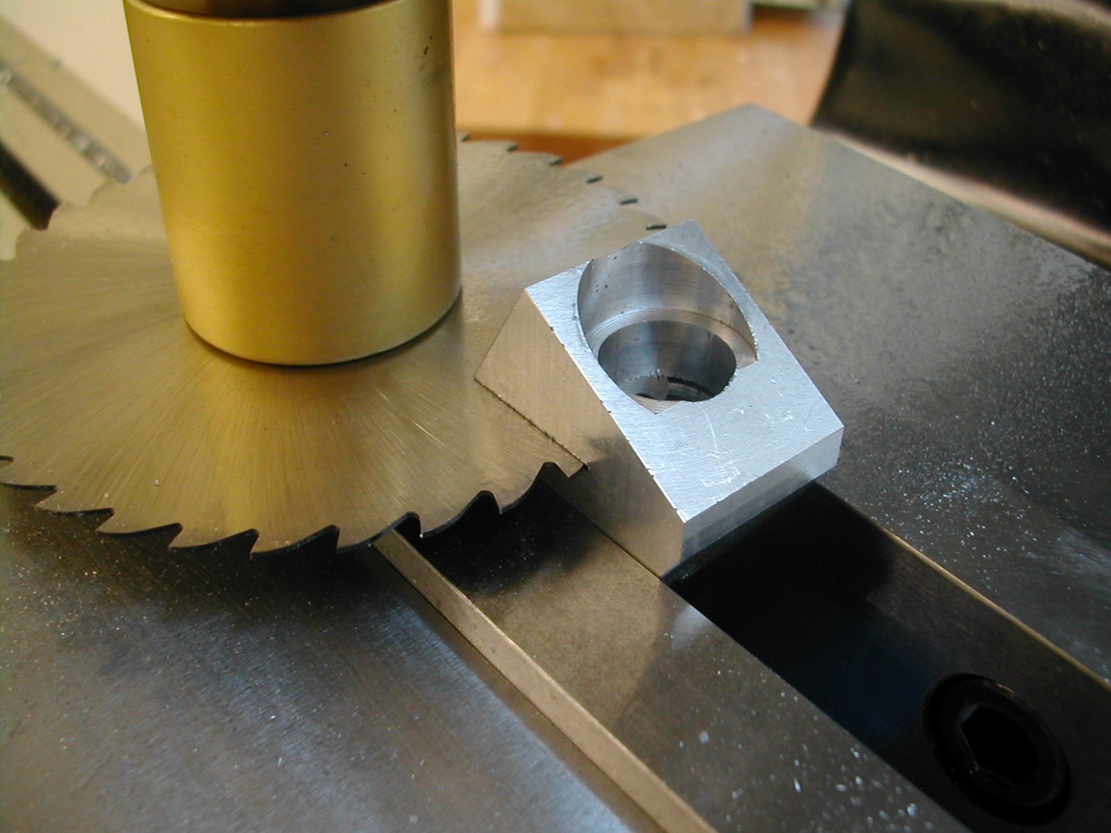 I didn’t like the mark left by the setscrew in Michael’s fixture so I decided to change to a pinch bolt clamp. With the fixture still clamped at 30° I ran a 1/32″ slitting saw just above the bottom of the ø0.615″ bore so that the seating surface would not be affected.
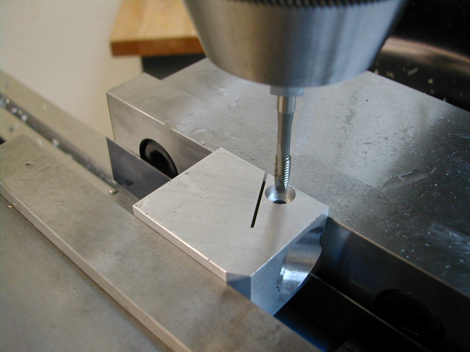 The fixture was flipped on its side and body drilled for a #8 screw half way through, and counterbored with a 5/16″ endmill. A tap drill was then run through and the bottom half tapped #8-32.
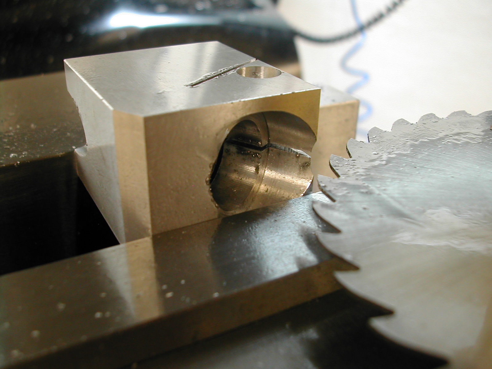 The last step on the fixture was to split the clamp portion in to two halves.
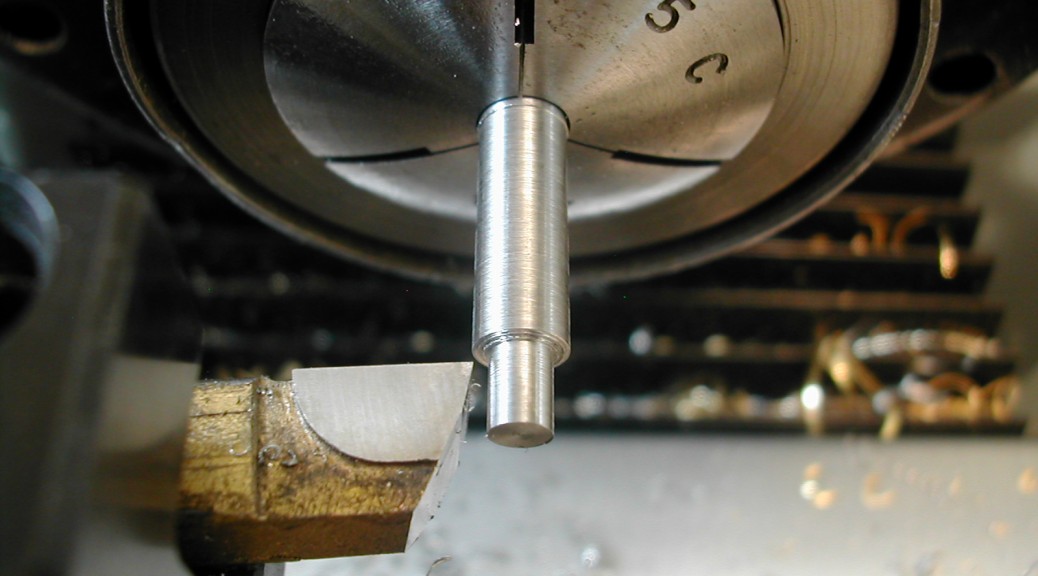
 The spindles were previously partially completed in the making of the gears. Now one is mounted in the fixture and an endmill is used to make a flat on the saw-cut end.
 The height of the spindle above the fixture was measured and re-cut until the CAD generated dimension was reached.
 Since everything was done in CAD, its a simple matter of indicating the block and moving over to the hole location. Since I wanted to make sure and not cause the part to rotate while drilling, I stepped up the drill sizes to 19/64″.
 I first opened the bore up to 0.3125″ all the way through, and then working on 0.010″ steps off the diameter and down 0.196″, I stepped out to ø0.5005″.
 By doing 0.005″ step overs, I ended up with a flat bottom counterbore without having to face the bottom. My eBay Wohlhaupter boring head could have easily faced the bottom, but since my boring bar was so small I needed to use small steps anyway.
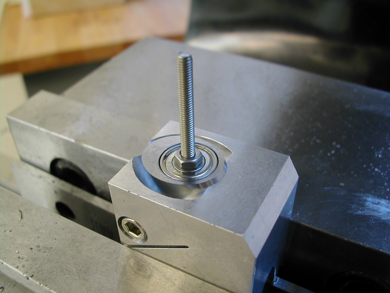 A temporary handle in the bearings makes checking the fit easy.
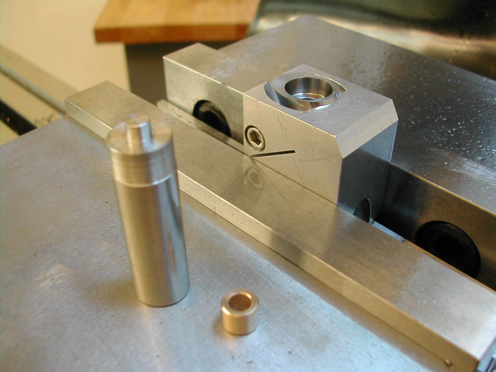 Here’s the little press arbor I made to press in the purchased Oilite 5/16×3/16×1/4 bushings. The arbor OD is just under 1/2″ so it will seat the bushing flush with the bottom of the bearing bore.
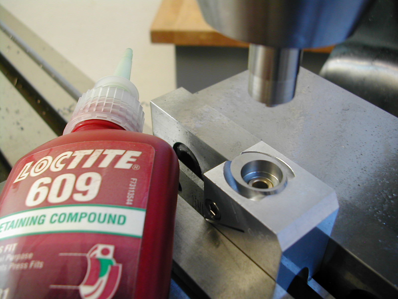 A light coating of press-fit retaining compound and the bushing was pressed home.
 After a short drying time, a reamer was passed through the bushing and the fit was checked on the Spindle.
Only after all of these steps were completed on the first Spindle Housing was the fixture clamp screw loosened and the housing removed. The second housing was installed in the fixture and the process repeated.
 Both housings were deburred, and the ball bearing ODs were coated with a light coat of retaining compound and the bearings pushed home. A light coat of retaining compound was placed only near the shoulder on the spindles and the Spindle Housing with bearing and bushing was lowered over it. These were left in an upright position while drying to make sure no retaining compound wicked between the spindle and bronze bushing.
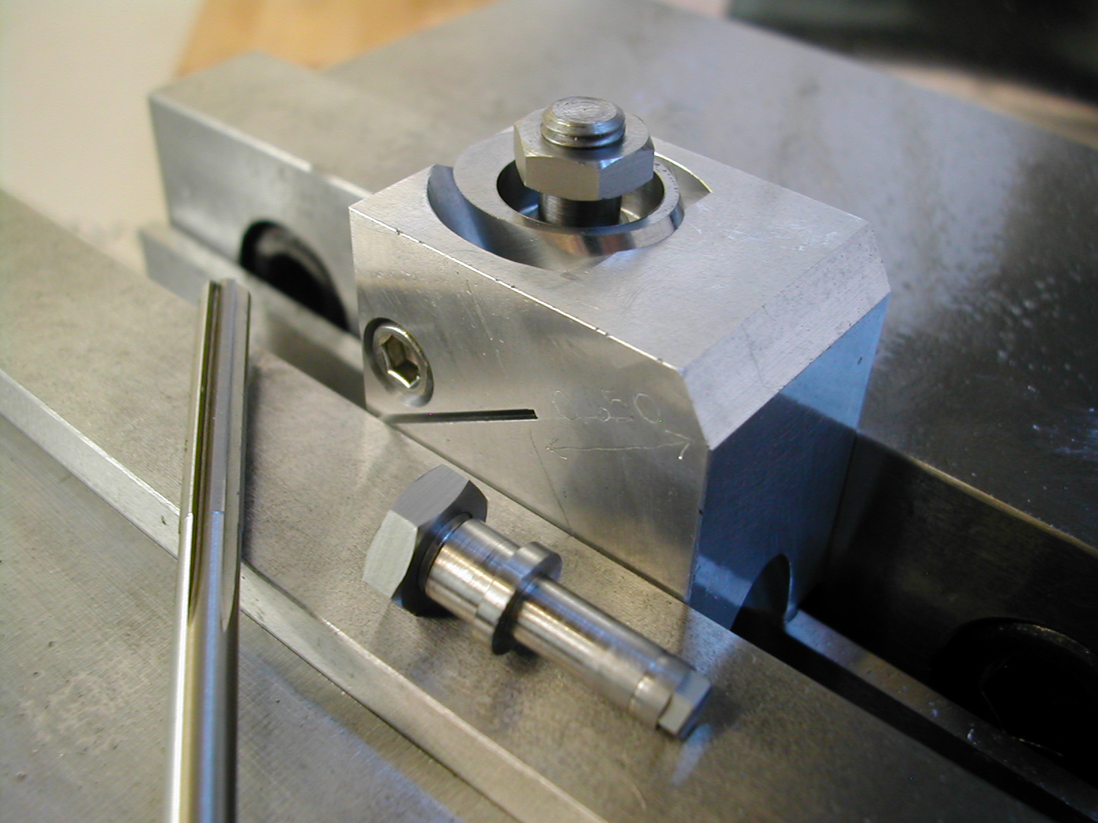
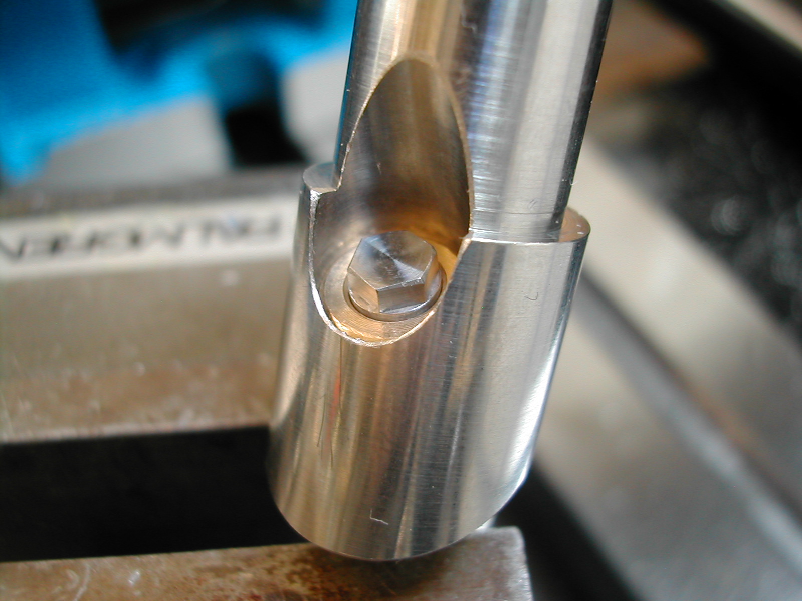 And here’s a final close-up of the spindle and spindle housing.
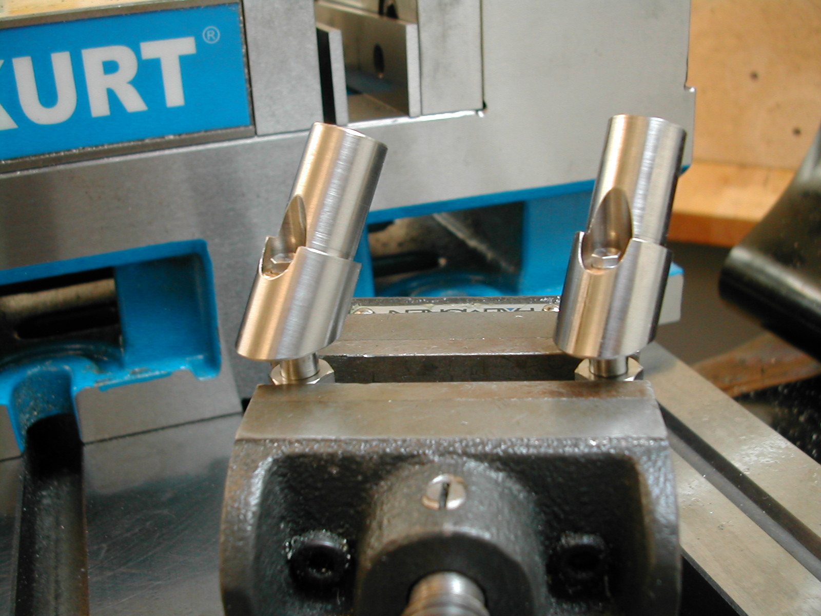
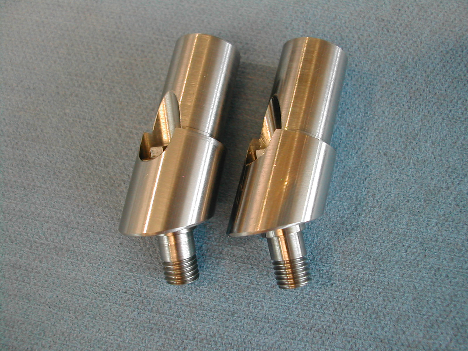 Here are the assembled spindles and housings. You can clearly see the left-hand and right-hand threaded spindles in this photo.
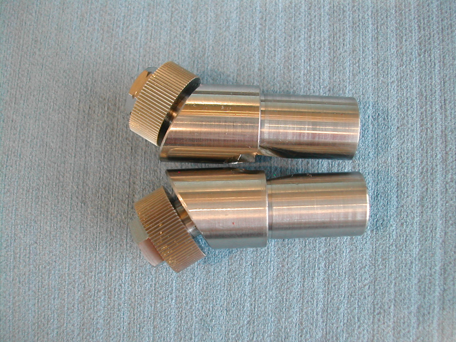 All finished with the knurls installed. Note the grooved nut denoting the left-handed spindle. With these completed, it’s time to start on the two locking levers.
Disclaimer and License
All material, including the CAD drawings, relating to the construction of the Cut Knurling Tool presented on this site is free to use any way you see fit. However, no guarantees are made regarding the accuracy or correctness of the material presented here.
Downloads
(CAD drawings are in SolidWorks 2013 Format)