
 Details 19 & 20, the Small and Large Gears
In Michael’s article, he presents an excellent write-up on gear design and a pseudo-hobbing technique to make custom gears. I didn’t have the tool steel to make the cutter, nor the time to actually cut the gears so I threw a little money at the problem instead. Stock Drive Products/Sterling Instrument is a great company for small mechanical components. Their 64 D.P. 20° Pressure Angle pinion wire comes in both brass and carbon steel and is fairly inexpensive. I bought a foot of their A 1C 9-Y641016 16-tooth carbon steel pinion stock for the small gears, and a foot of A 1B 9-Y641034 34-tooth brass pinion stock for the large gears.
Because SDP’s pinion stock is 64DP instead of 80DP, my gears have different pitch diameters than what Michael designed for and I needed to adjust the small gear locations. These were fairly small adjustments and the purchased pinion stock saved a bunch of time, so I’m happy with the change.
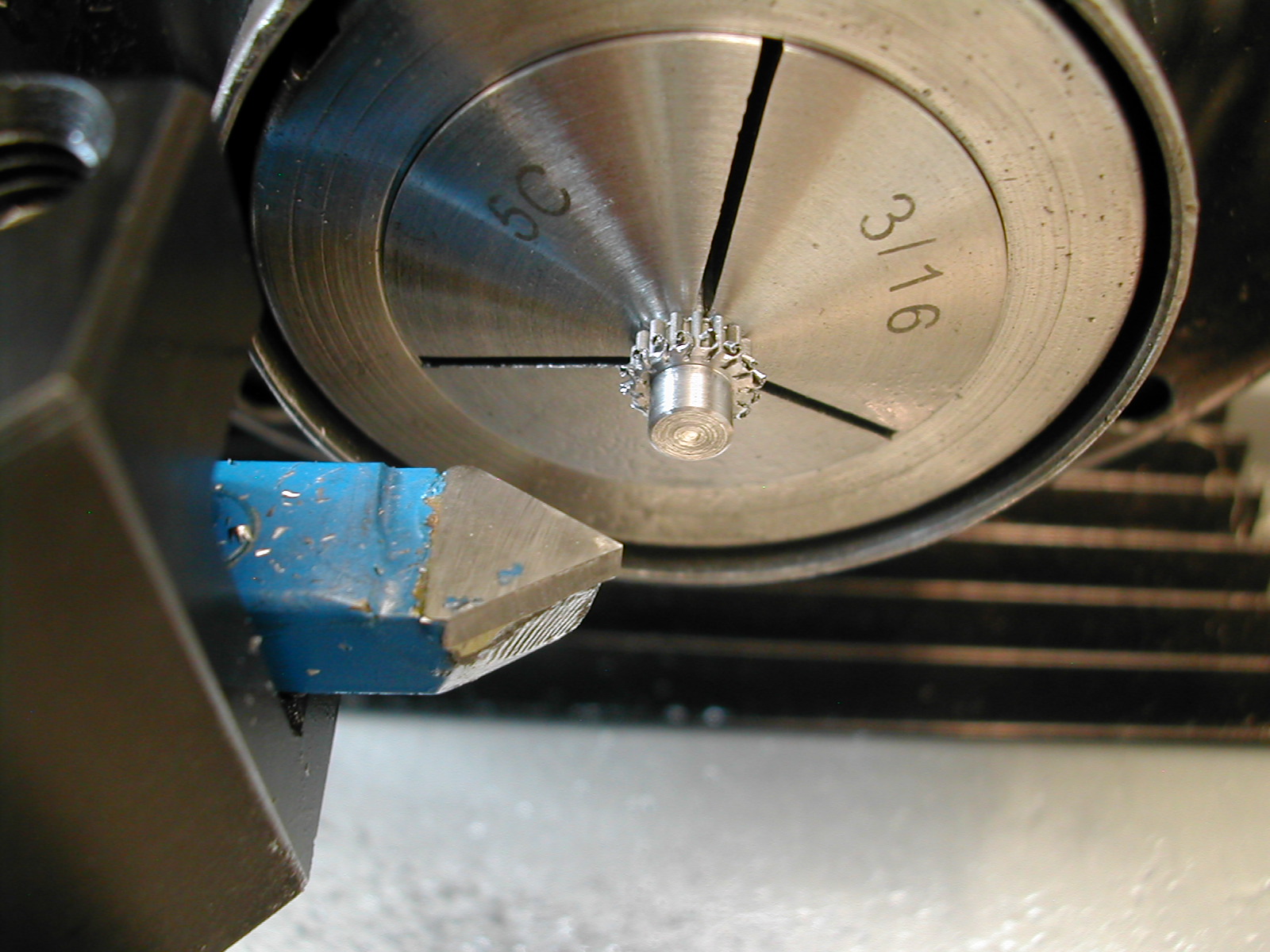
 With the 16-tooth steel pinion stock loaded in a collet, I’m turning the 3/16″ long by ø3/16″ stubs. These are turned to fit the holes in the tool holder head so they turn freely but with minimal clearance. the fit can be verified by sliding the head onto the stub before cutting off.
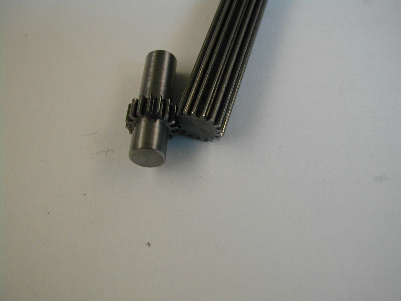
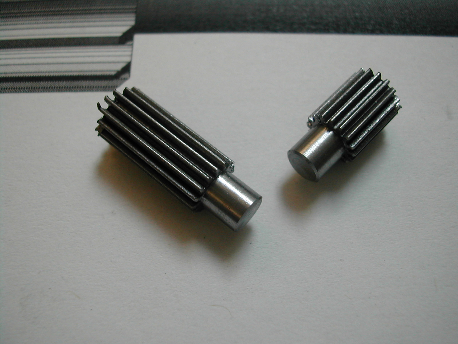 These are the two small gears rough sawn to length. I cut them off with a hacksaw right on the lathe.
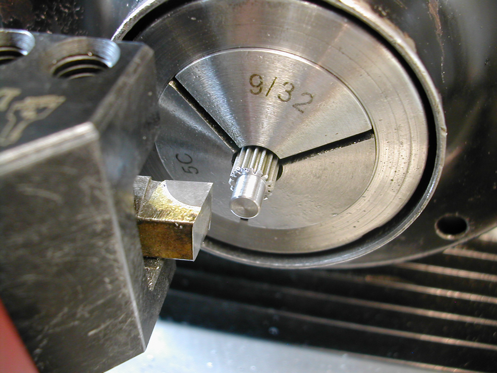
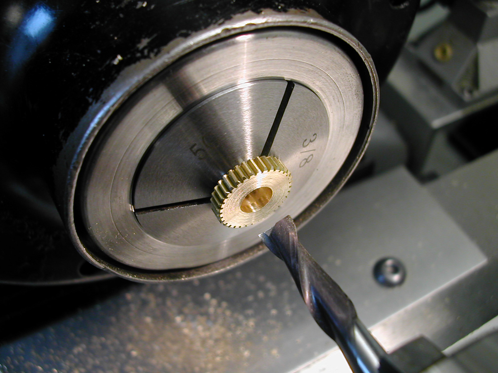
 The small gears are then held in a ø3/16″ collet by the previously machined stubs and the other side turned and fit to the Tool Holder Head Backing Plate.
 A small 30° chamfer will take off most of the burrs.
 The remaining burrs are easily removed by facing the end of the remaining pinion stock and using it as a scraper to knock off the remaining burrs from the finished pinions.
 Before I could turn the large gears, I need to at least start on the Spindle Housings so that I could fit both the ø3/8″ boss OD and length on the large gears. So I’m turning the housings from some ø3/4″ 17-4 H1150 rod.
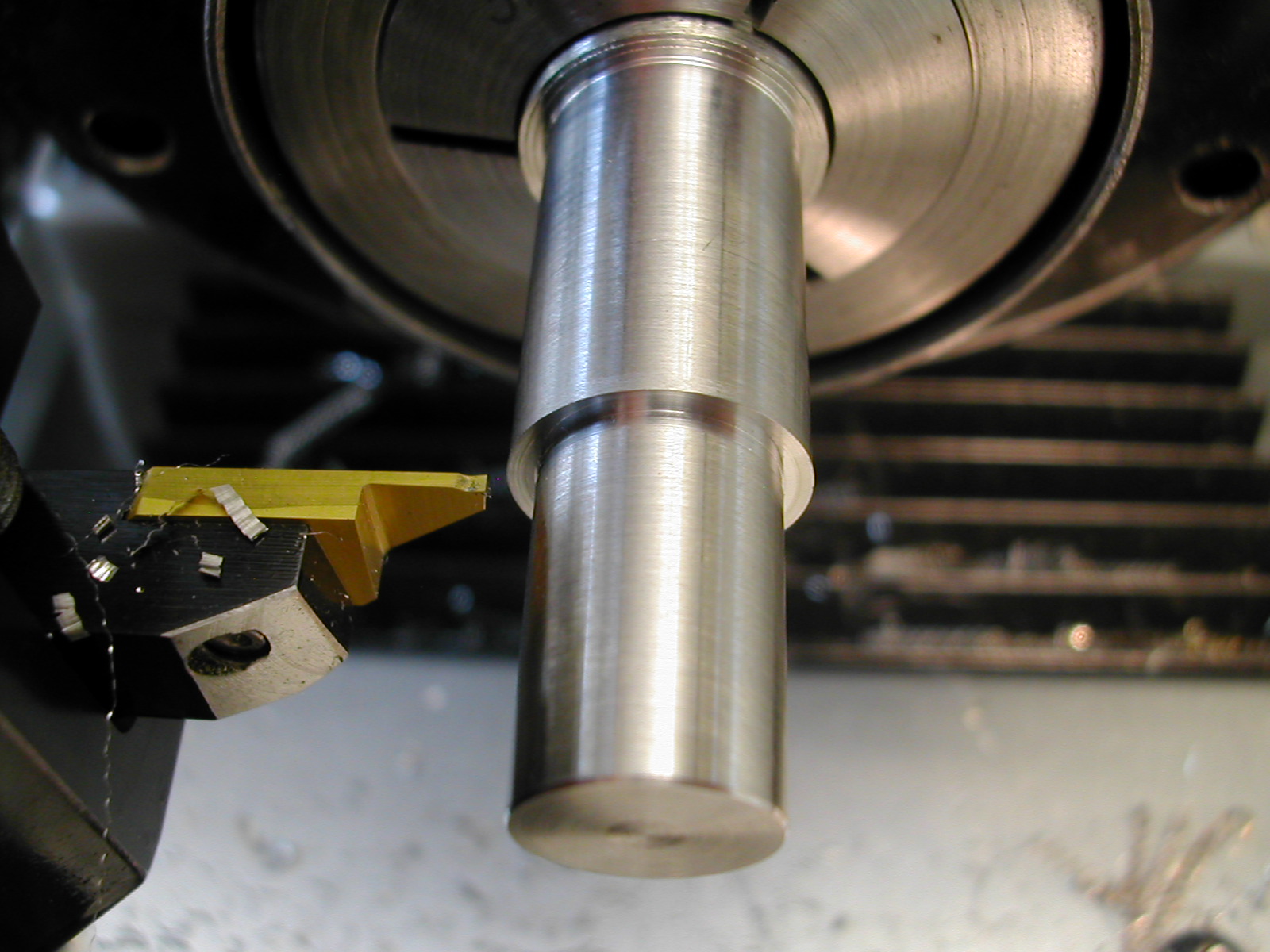
Michael has the ø0.5000″ length at 0.751″ to set the fit in the Tool Holder Head. I felt it was better to shorten this dimension to 0.740″ and use the stub on the large gears to set the spindle end-play in the head. The diameter was fit to the previously completed head to get smooth rotation without play. Here, I’ve just completed a slight undercut to make sure the face sits flush with the head when inserted.
 The ø0.615″ section was turned at the same time as the ø0.500″ section so they should be concentric. The final step before sawing off the rough Spindle Housing is to add the 0.375" deep by ø3/8″ C’bore for the large gear, and a larger #6-32 tapped hole.
Try to keep these dimensions as close as possible because we need to make another spindle housing blank just like this and they both have to fit the same fixture later.
 Now that we have the ID’s finished on two partially complete spindle housings, we can start on the large gears that need to fit in these counterbores. The diameter has been turned to be a close fit in the spindle housing but the length is left a little long. A small chamfer has been added to the gear edge, and a clearance hole for the #6 SHCS has been drilled.
 Now, the Tool Holder Head and partially completed Spindle Housing are assembled on the large gear boss. Keep pressure on the end of the Spindle Housing and check that the Head rotates freely without perceptible end-play. Remove a small amount from the end of the large brass gear and re-test until there is no end-play apparent.
Once there, hacksaw off this large gear and repeat for the other gear/spindle pair.
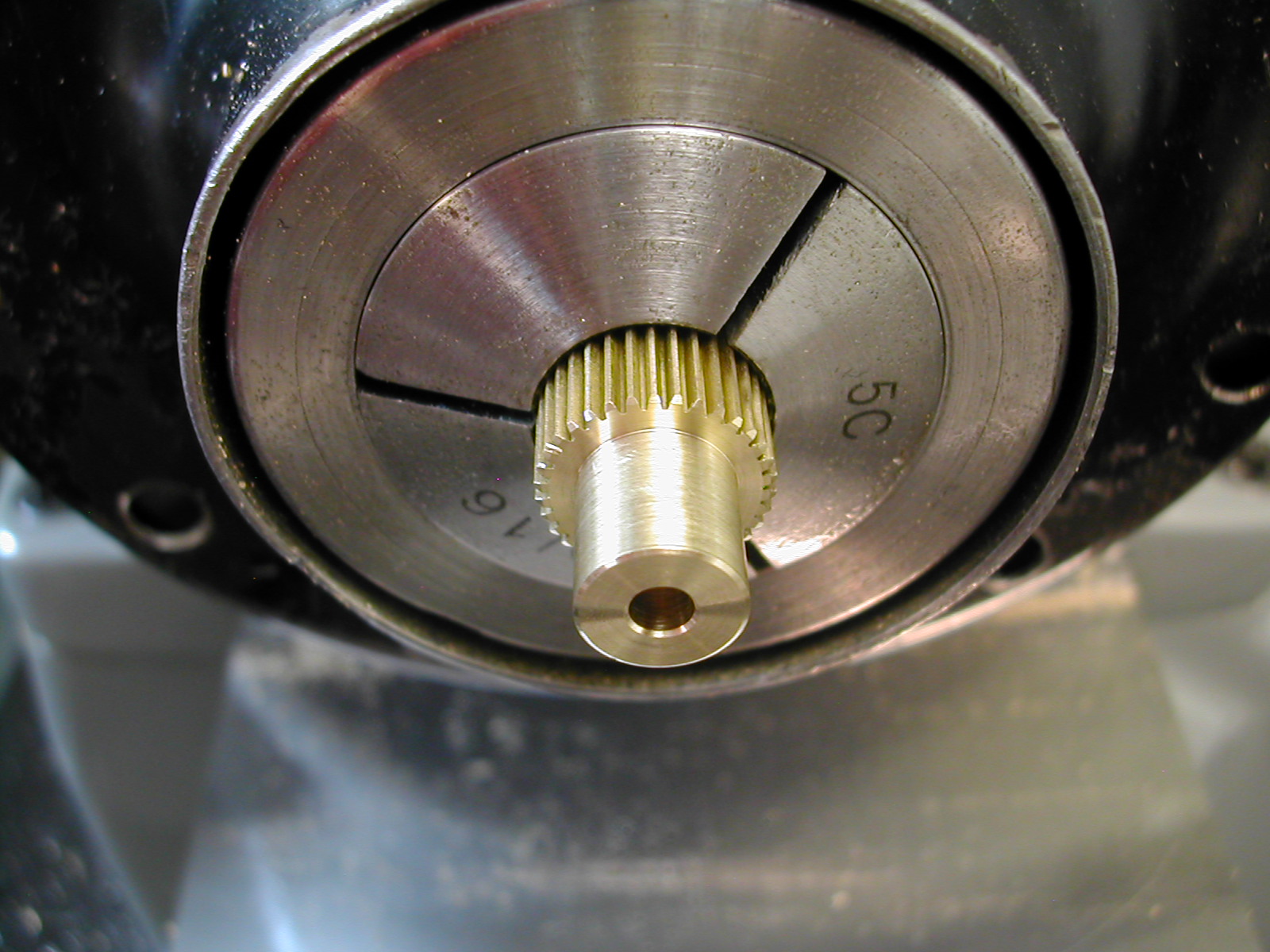
 Now that the gear blanks have been fit to the spindles, pop each one in a ø3/8″ collet and face the gear section down to 0.124″ thick then add a 0.205″ deep by ø1/4″ counterbore for the larger #6-32 SHCS. Chamfer the other edge of the gear, and deburr with the same technique previously used on the small gears.
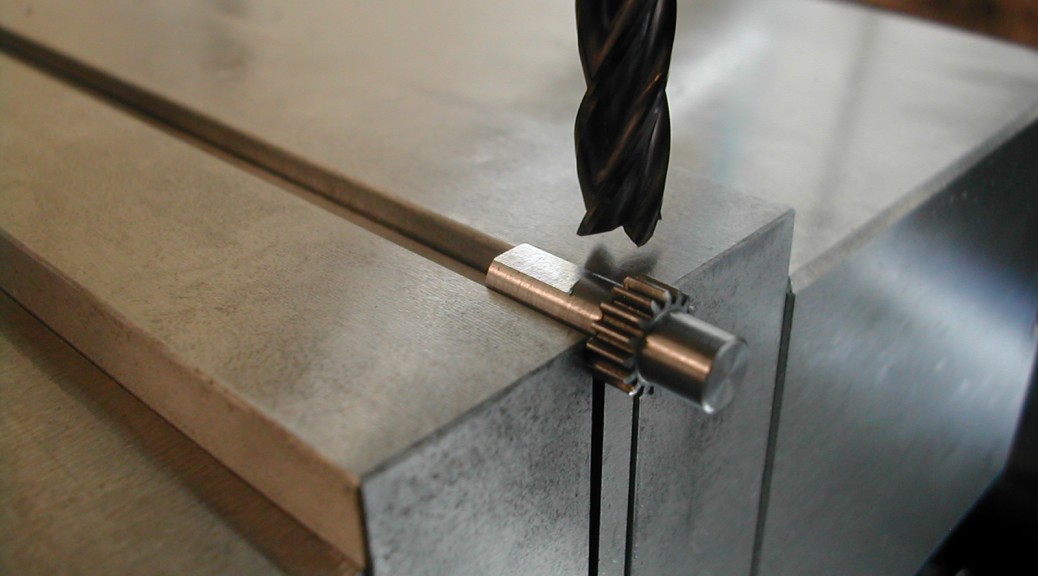
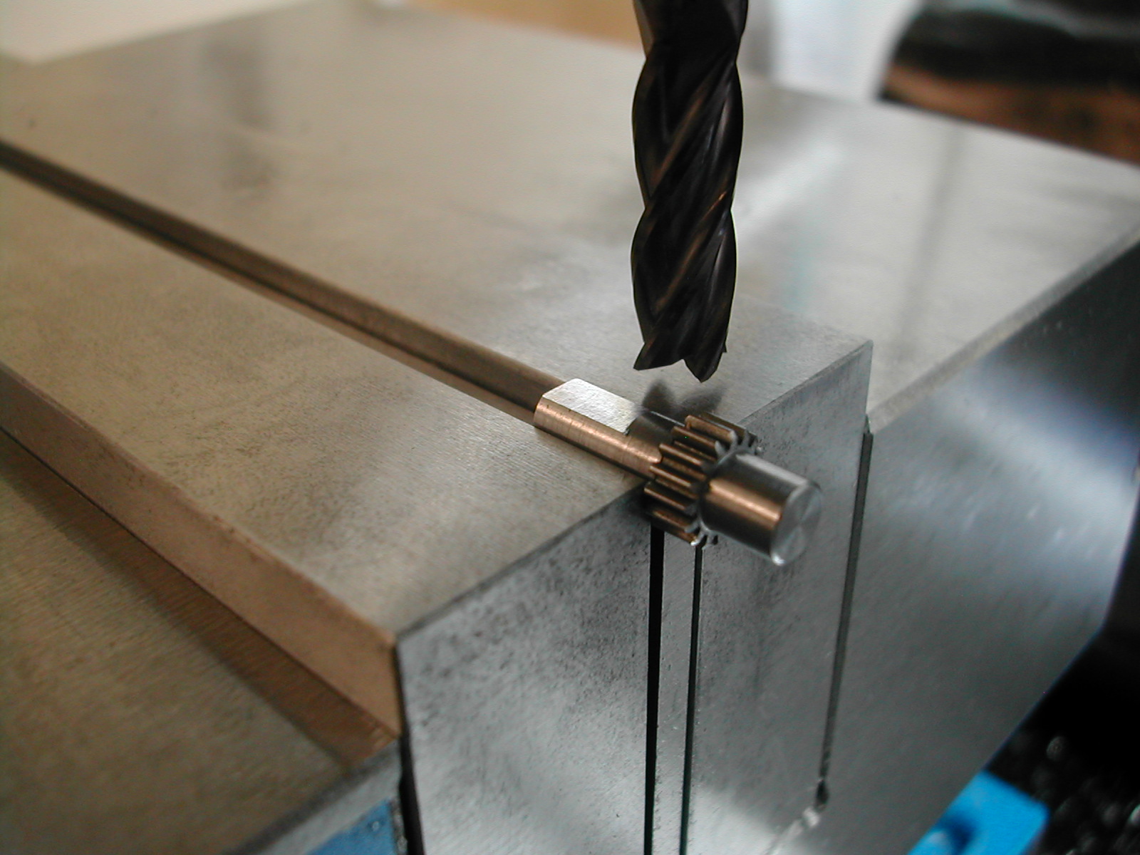
The final task on the gears is to hop back on the mill to quickly add the flat on the extended small gear.
Disclaimer and License
All material, including the CAD drawings, relating to the construction of the Cut Knurling Tool presented on this site is free to use any way you see fit. However, no guarantees are made regarding the accuracy or correctness of the material presented here.
Downloads
(CAD drawings are in SolidWorks 2013 Format)