While there are a lot of shared 3D CAD models on the internet, sometime you really need to know that the model is accurate. The only sure way to do this it to create it yourself. This post will help you create accurate involute gears in SolidWorks.
To accurately generate involute curves in SolidWorks we will be using Equation Driven Curves in our sketches. That means we will be needing some equations, and there are quite a few for involute gears:
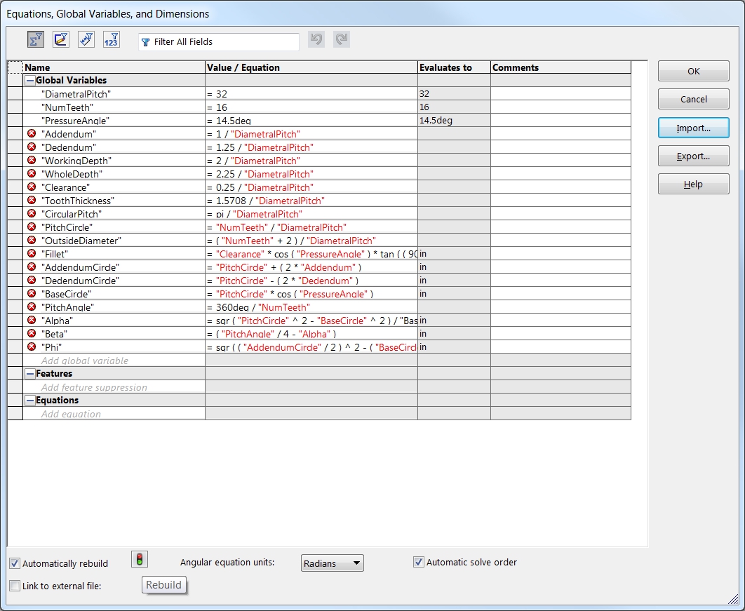
"DiametralPitch"= 32
"NumTeeth"= 16
"PressureAngle"= 14.5deg
"Addendum"= 1 / "DiametralPitch"
"Dedendum"= 1.25 / "DiametralPitch"
"WorkingDepth"= 2 / "DiametralPitch"
"WholeDepth"= 2.25 / "DiametralPitch"
"Clearance"= 0.25 / "DiametralPitch"
"ToothThickness"= 1.5708 / "DiametralPitch"
"CircularPitch"= pi / "DiametralPitch"
"PitchCircle"= "NumTeeth" / "DiametralPitch"
"OutsideDiameter"= ( "NumTeeth" + 2 ) / "DiametralPitch"
"Fillet"= "Clearance" * cos ( "PressureAngle" ) * tan ( ( 90 + "PressureAngle" ) / 2 )
"AddendumCircle"= "PitchCircle" + ( 2 * "Addendum" )
"DedendumCircle"= "PitchCircle" - ( 2 * "Dedendum" )
"BaseCircle"= "PitchCircle" * cos ( "PressureAngle" )
"PitchAngle"= 360deg / "NumTeeth"
"Alpha"= sqr ( "PitchCircle" ^ 2 - "BaseCircle" ^ 2 ) / "BaseCircle" * 180 / PI - "PressureAngle"
"Beta"= ( "PitchAngle" / 4 - "Alpha" )
"Phi"= sqr ( ( "AddendumCircle" / 2 ) ^ 2 - ( "BaseCircle" / 2 ) ^ 2 ) / ( "BaseCircle" / 2 )
The first three equations: DiametralPitch, NumTeeth, and PressureAngle will vary depending on the particular part and you will need to determine their values before we begin. With the math out of the way, let’s get started.
- Select Tools / Equations…
- In the Equation dialog change Angular equation units to Degrees
- Enter each of the above equations into the table into the Global category
-or-
download the equations and select Import to add them to the table
(click the rebuild icon to resolve any errors)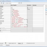
Gear Equation Dialog - Select OK to exit the dialog
- Select Insert / Boss/Base / Extrude… to create a cylindrical gear blank
- select a plane or face to start the gear
- sketch a circle and dimension the diameter to =”OutsideDiameter”
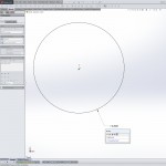
Gear Boss Extrude - exit the sketch
- extrude boss to the face width of your gear
- select OK
- Select Insert / Cut / Extrude… to begin the tooth gullet
- select the end face of the cylinder for the starting surface
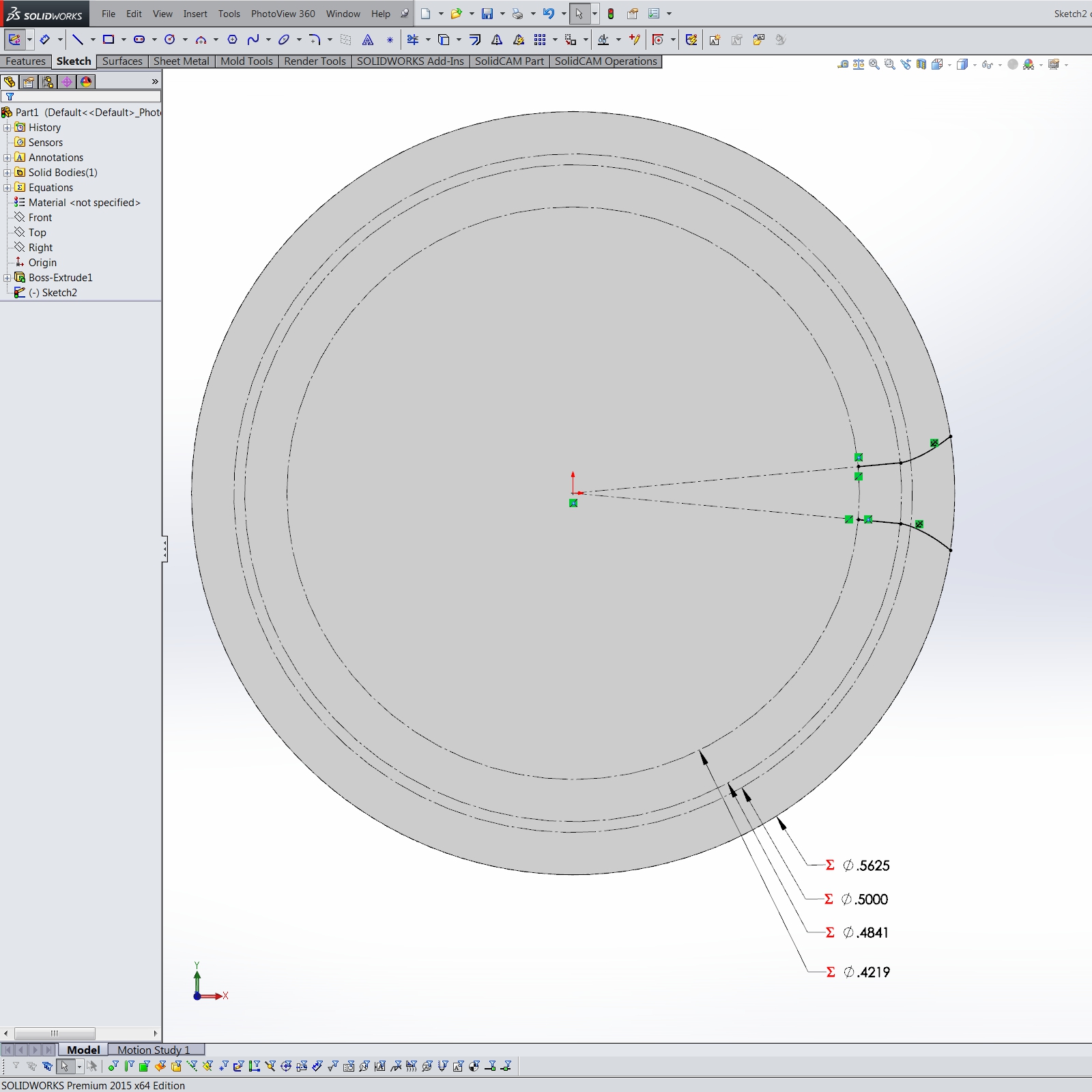
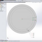
- Sketch four construction circles concentric with the OD of the boss
- dimension the circles to:
=”OutsideDiameter”
=”PitchCircle”
=”BaseCircle”
=”DedendumCircle”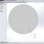
Gear Construction Circles
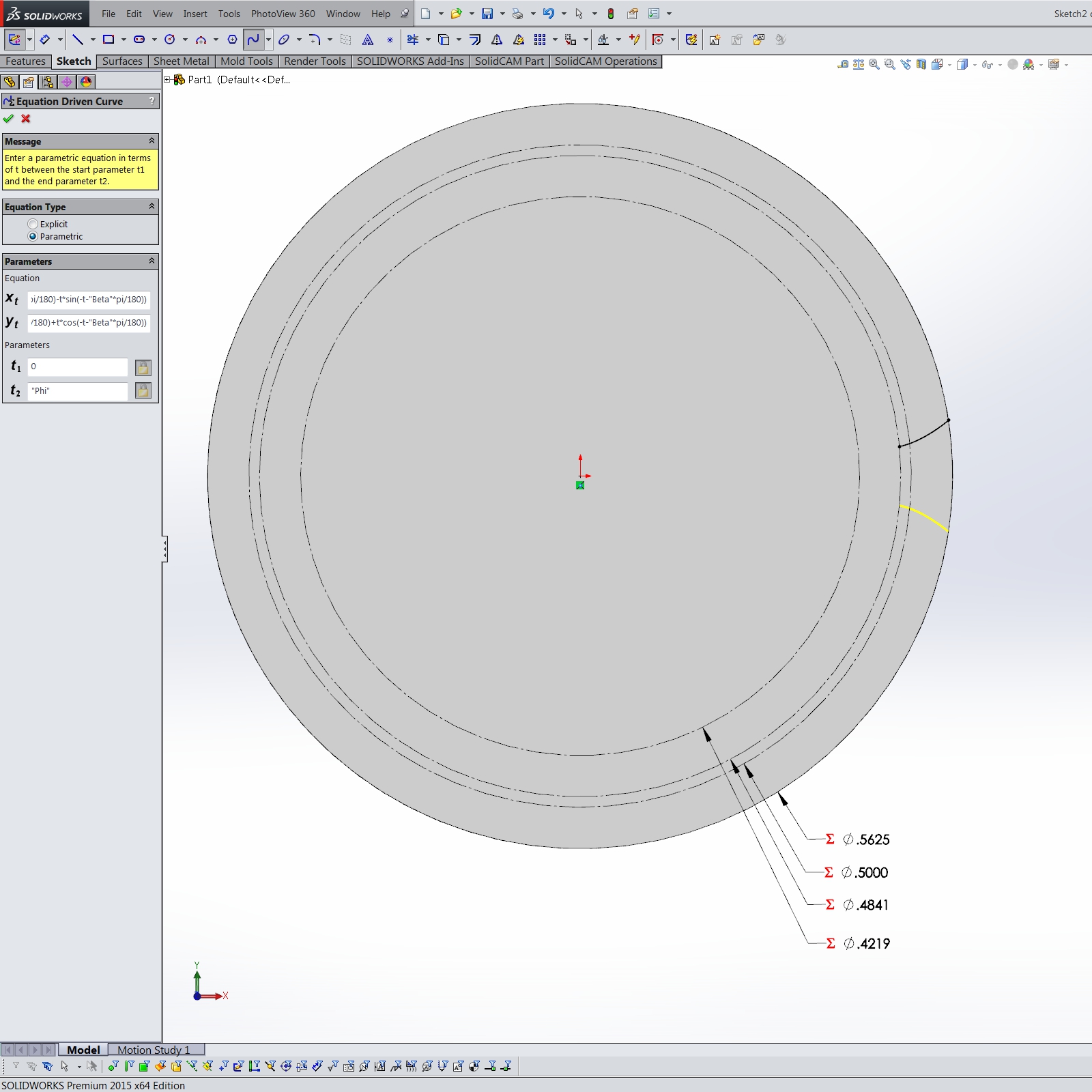
- Create the upper involute curve
- select Tools / Sketch Entities / Equation Driven Curve
- choose Parametric
- for Equation xt enter
"BaseCircle"/2*(cos(t+"Beta"*pi/180)+t*sin(t+"Beta"*pi/180)) - for yt enter
"BaseCircle"/2*(sin(t+"Beta"*pi/180)-t*cos(t+"Beta"*pi/180)) - set Parameter t1 to
0 - set Parameter t2 to
"Phi"
Upper Involute Curve - select OK to create the curve
- add a Fix relation to the newly created parametric curve
- Create the lower involute curve
- select Tools / Sketch Entities / Equation Driven Curve
- choose Parametric
- for Equation xt enter
"BaseCircle"/2*(cos(-t-"Beta"*pi/180)-t*sin(-t-"Beta"*pi/180)) - for yt enter
"BaseCircle"/2*(sin(-t-"Beta"*pi/180)+t*cos(-t-"Beta"*pi/180)) - set Parameter t1 to
0 - set Parameter t2 to
"Phi"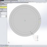
Lower Involute Curve - select OK to create the curve
- add a Fix relation to the newly created parametric curve
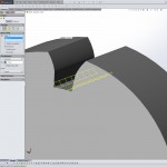
- Create the lower portion of the tooth gullet
- add a radial construction line from the dedendum center towards the beginning of the upper involute curve ending at the dedendum circle
- add a line from the end of the previous construction line to the beginning of the upper involute curve
- add a Collinear relation to both lines
- Repeat step 9 for the lower involute curve
Lower Gullet Portions - Cap the top and bottom of the gullet with arc segments Tangent (SolidWorks seems to have a problem with the Coradial relation in this case) with the dedendum circle (base circle if smaller) and outside diameter
- Exit the sketch
- Select Through All for the extrude cut End Condition and select OK to cut the tooth gullet
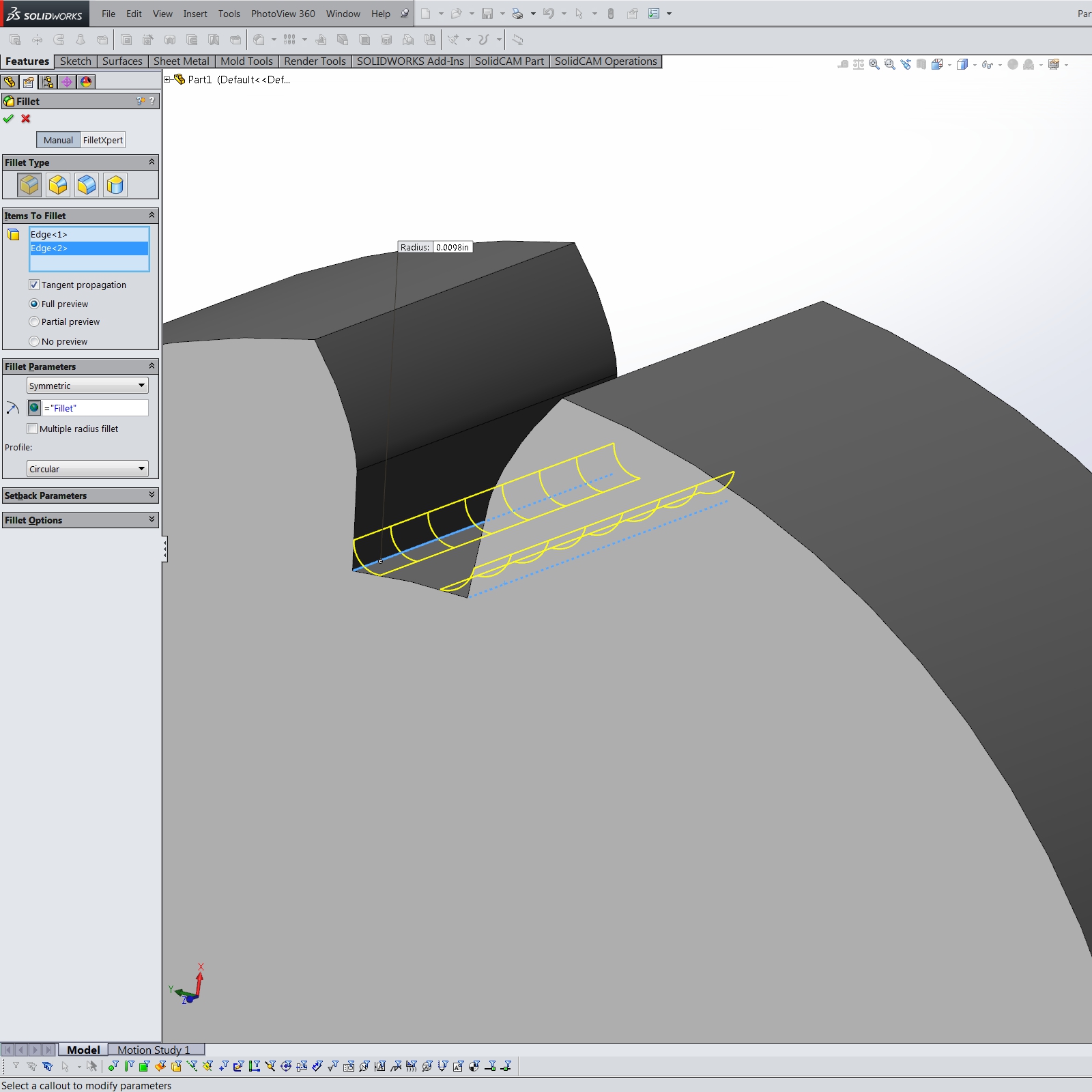
- Select Insert / Features / Fillet/Round…
- select Manual
- set Constant Size Fillet type
- for Parameters select Symmetric and for Size enter =”Fillet”
- select the two edges along the dedendum circle for Items To Fillet
- select OK to create the root fillets
Root Fillets
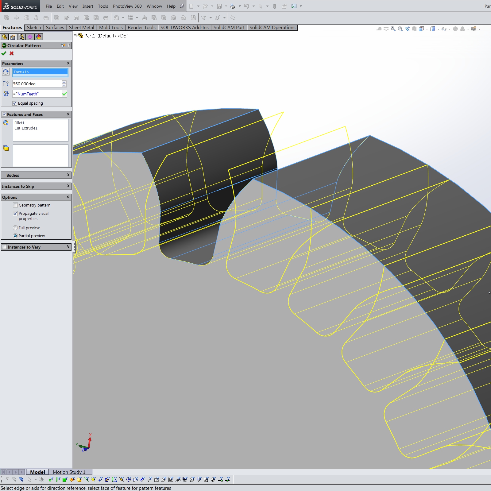
- Select the Cut-Extrude and the Fillet features from the feature tree
- then select Insert / Pattern/Mirror / Circular Pattern…
- set the Pattern Axis to the cylinder OD face
- Angle should be 360°
- for Number of Instances enter =”NumTeeth”
- select OK to create the gear teeth
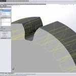
Patterning the Teeth
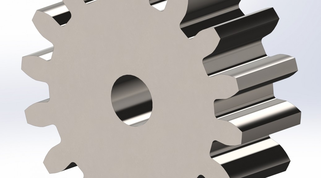
- Add a bore, keyway, setscrews, and hubs or other items to complete your gear


Note: On gears with a large number of teeth, the dedendum circle will sometimes become larger than the base circle. If this is the case on your gear, skip steps 9 and 10.