
- Hodgson Part 005, Bearing Retainer Plate
- Hodgson Part 007, Front Cover
After almost a 2-year hiatus, I was able to restart the Hodgson project. I have a small machine shop in the lab where I work at Harvard so I have a little opportunity to play on nights and weekends.
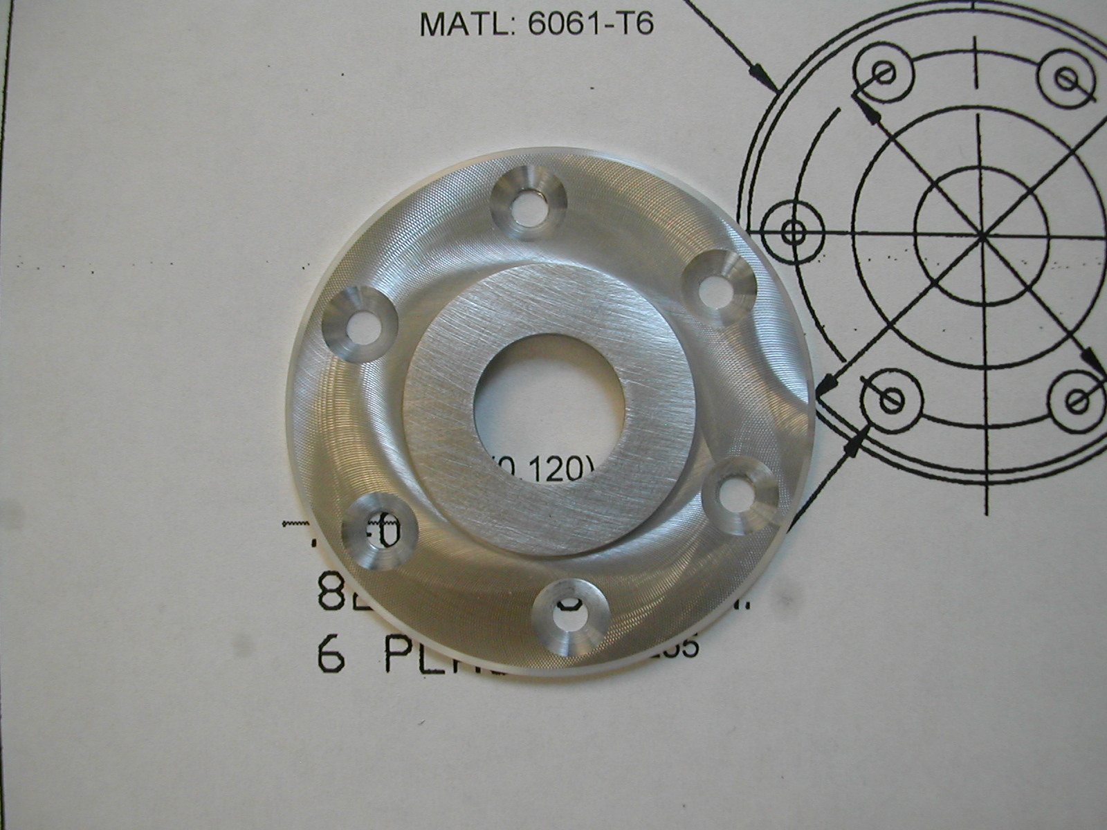
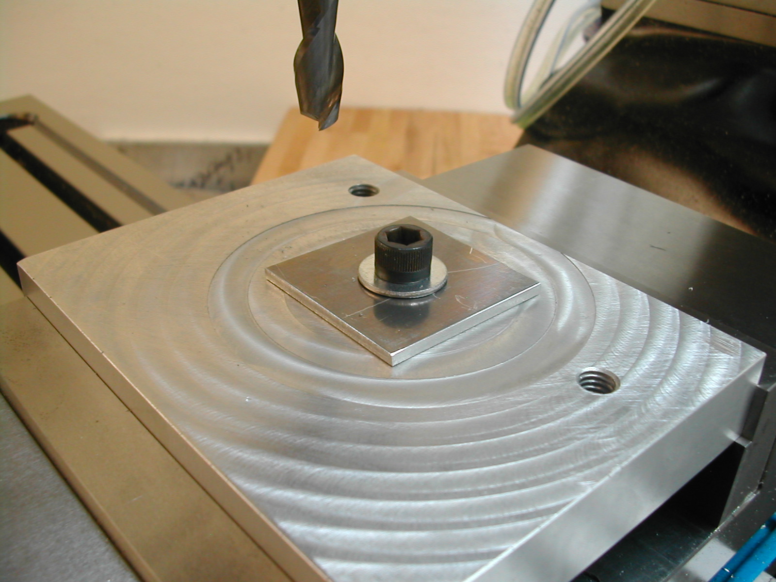 I used a piece 2″ x 2″ square of 0.125″ of Aluminum 7075-T6 plate to make the front bearing retainer. A 3/8″ hole was drilled in the center of the piece to mount it to a scrap tooling plate in the mill vise, and the center of the part was zeroed.
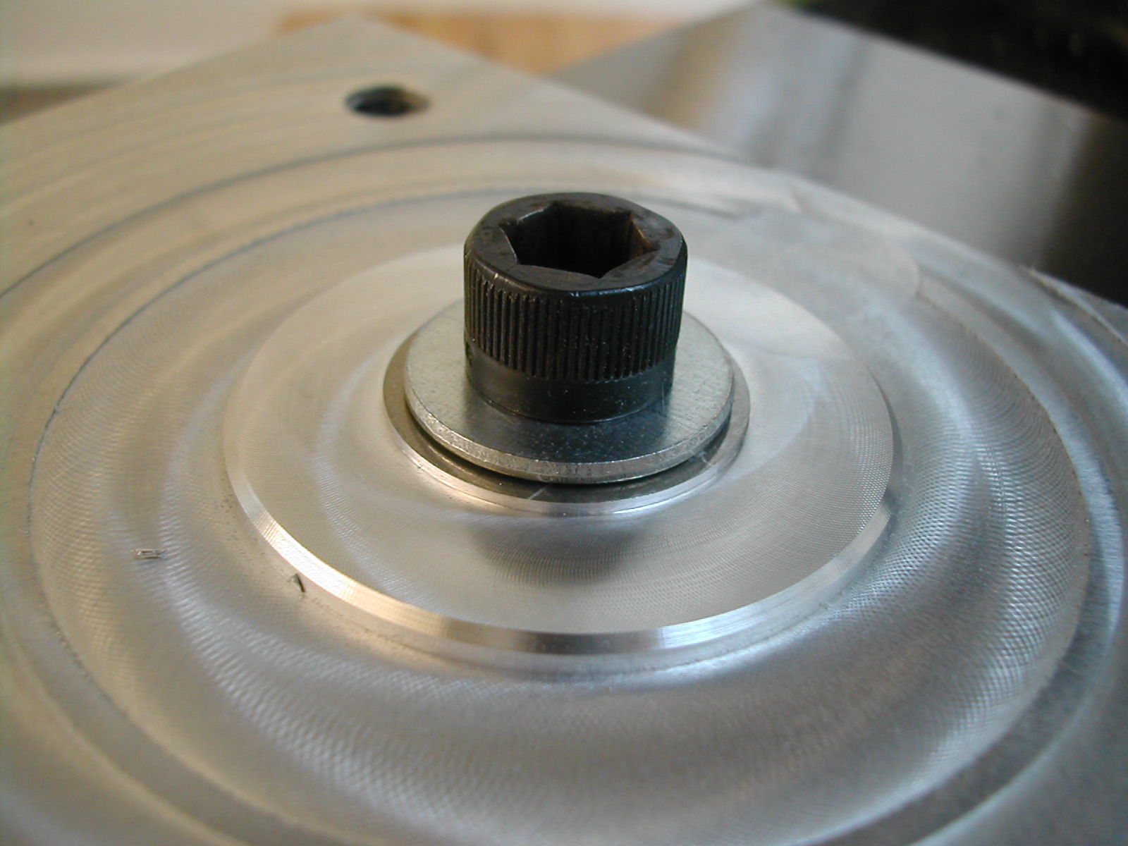 The outside perimeter and the step to create the boss were then milled with a 1/2″ endmill, and the chamfer was added.
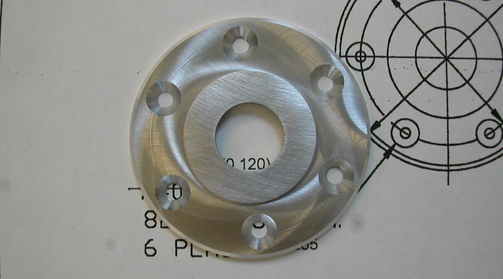
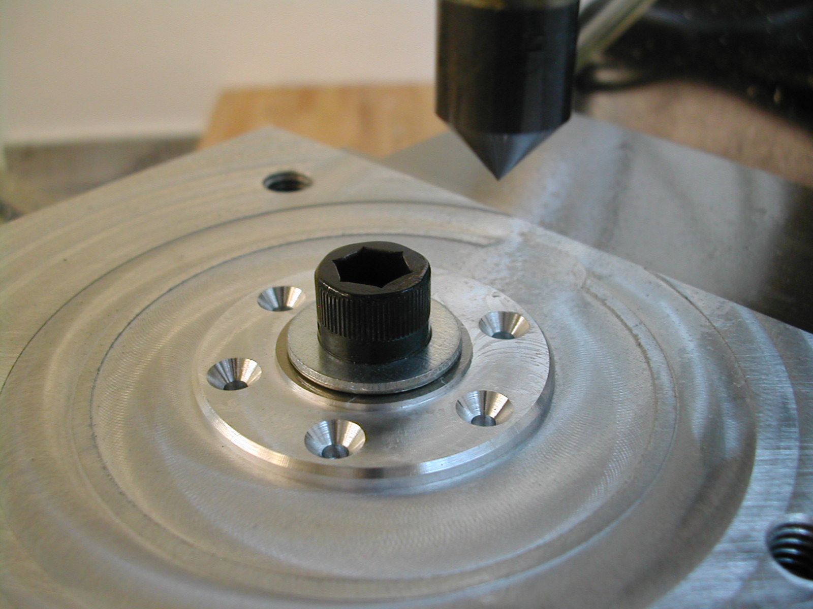 The six holes were then drilled and countersunk for the #4 screws completing the work on the upper surface. The clearance holes are 0.140″ instead of the normal clearance for a #4 screw because the countersink passes through the plate. The larger clearance hole prevents a sharp edge on the back side of the part.
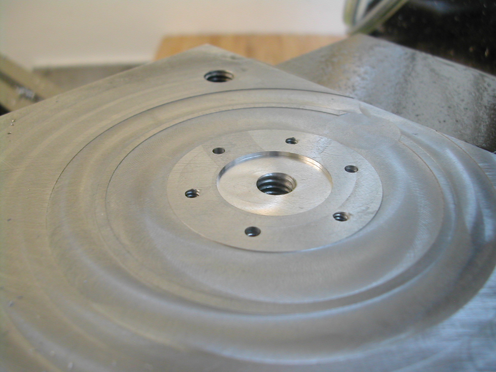 With the part removed, six #6-32 holes were tapped in the tooling plate to secure the part for work on the backside. A recess was also milled to clear the boss on the front of the bearing retainer plate.
 With the part remounted on the tooling block, the bearing inner race clearance recess was added and the center hole opened up to 0.510″.
 A quick lap of the raw mill‐finish on the upper unmachined surface of the plate completes the part.
Disclaimer and License
All material, including the CAD drawings, relating to the construction of the Hodgson Radial presented on this site is free to use any way you see fit. However, no guarantees are made regarding the accuracy or correctness of the material presented here.
Links Used On This Page
(CAD drawings are in AutoCAD 2010 Format)