
Details 9-11, the Height Adjustment Mechanism
 Detail 9, the Height Screw Nut is very straight forward, but I didn’t have any 3/16″ brass to start with so I’m turning down some 7/16″ stock which was itself oversize and wouldn’t fit my 7/16″ collet.
 A quick #6-32 tap and this part’s done!
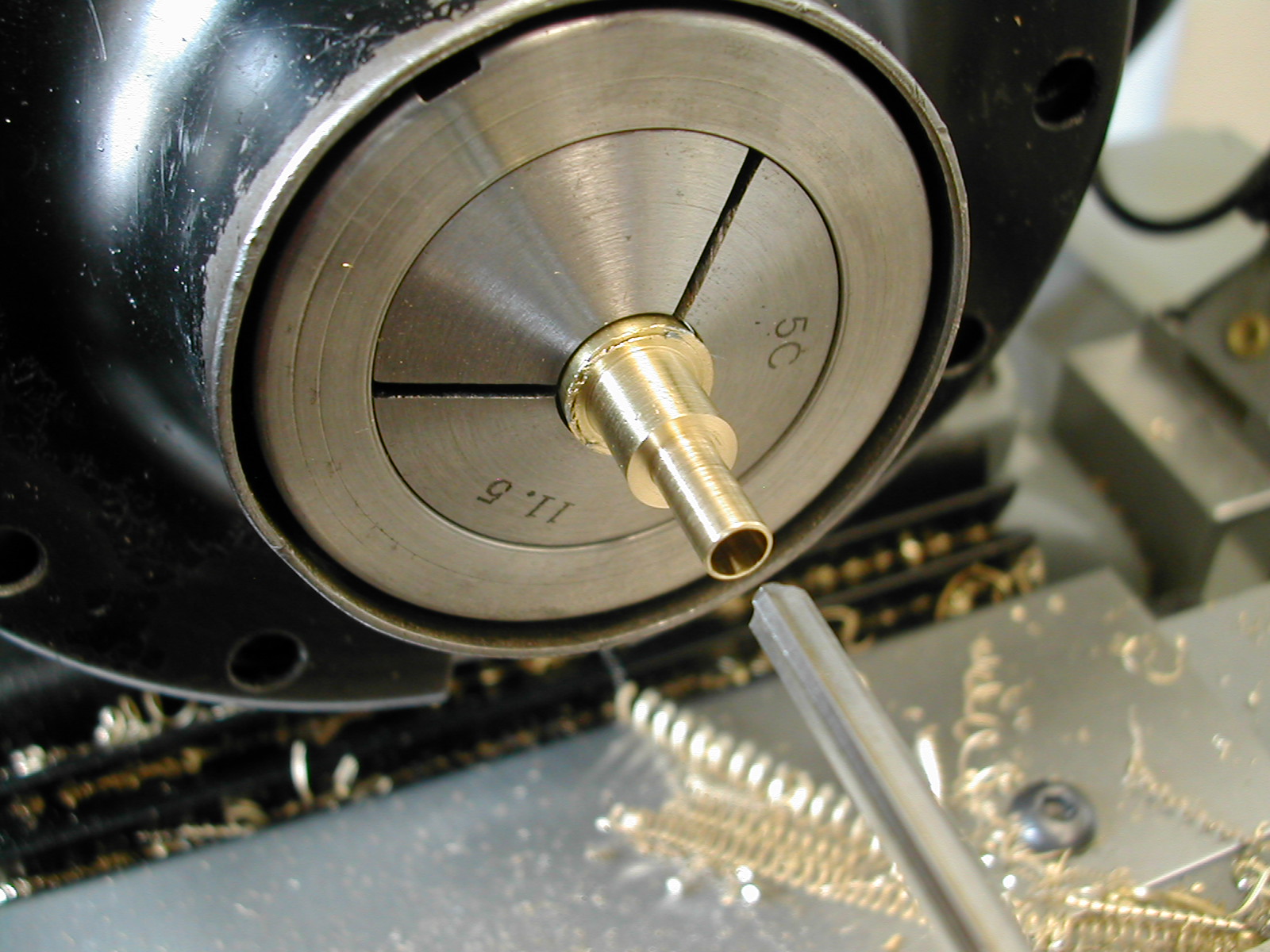 The Height Screw Bearing, Detail 10, started from the same piece of brass. First I turned back an inch to the ø5/16″ then followed with the ø3/16″ fitted to the Tool Holder Head. Before hacksawing this off to finish the top side, I drilled and reamed the 5/32″ hole for the Height Adjust Screw. You need a sharp reamer here or it will just stretch the thinwall tube out which will pop back when the reamer is removed.
 A radiused facing tool trims the saw cut end to the finished length and adds the little embellishment.
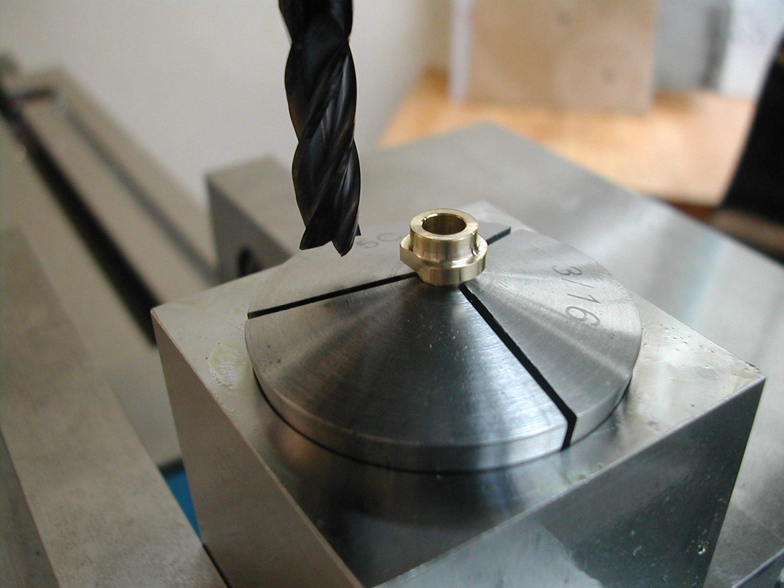 The last step on the bearing it to add the small flat to clear the Tool Holder Arm when the head is lowered.
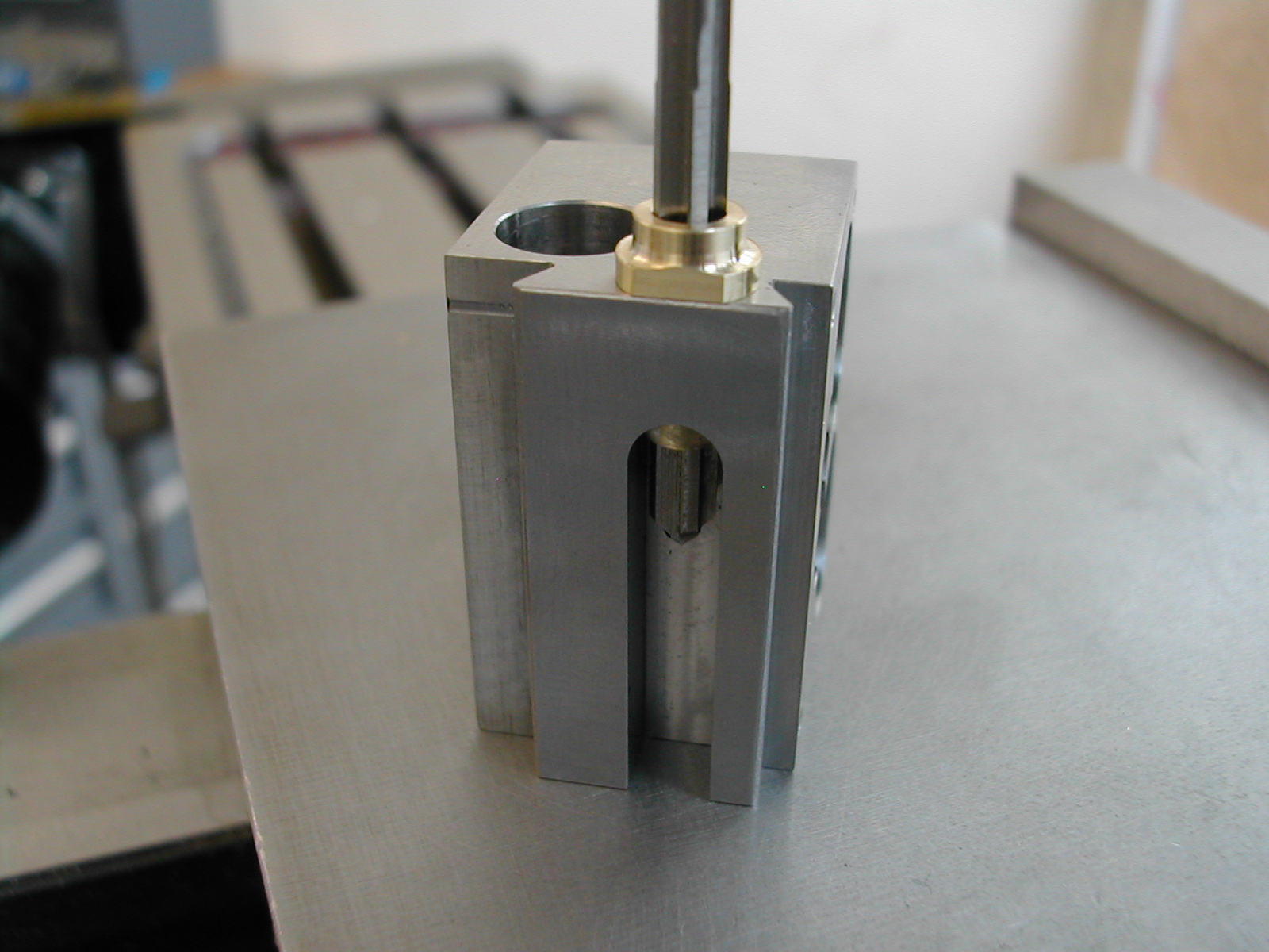 After installing the bearing in the Tool Holder Head and tightening the setscrew, I ran the 5/32″ reamer back through the bearing by hand in case the setscrew deformed the thinwall brass piece.
 Now on to Detail 11,the Height Screw. This was made out of 17-4 H1150 pre-heattreated material but the closest size I had was 1/2″ so I rough turned a 2″ section down to 1/4″ to get started.
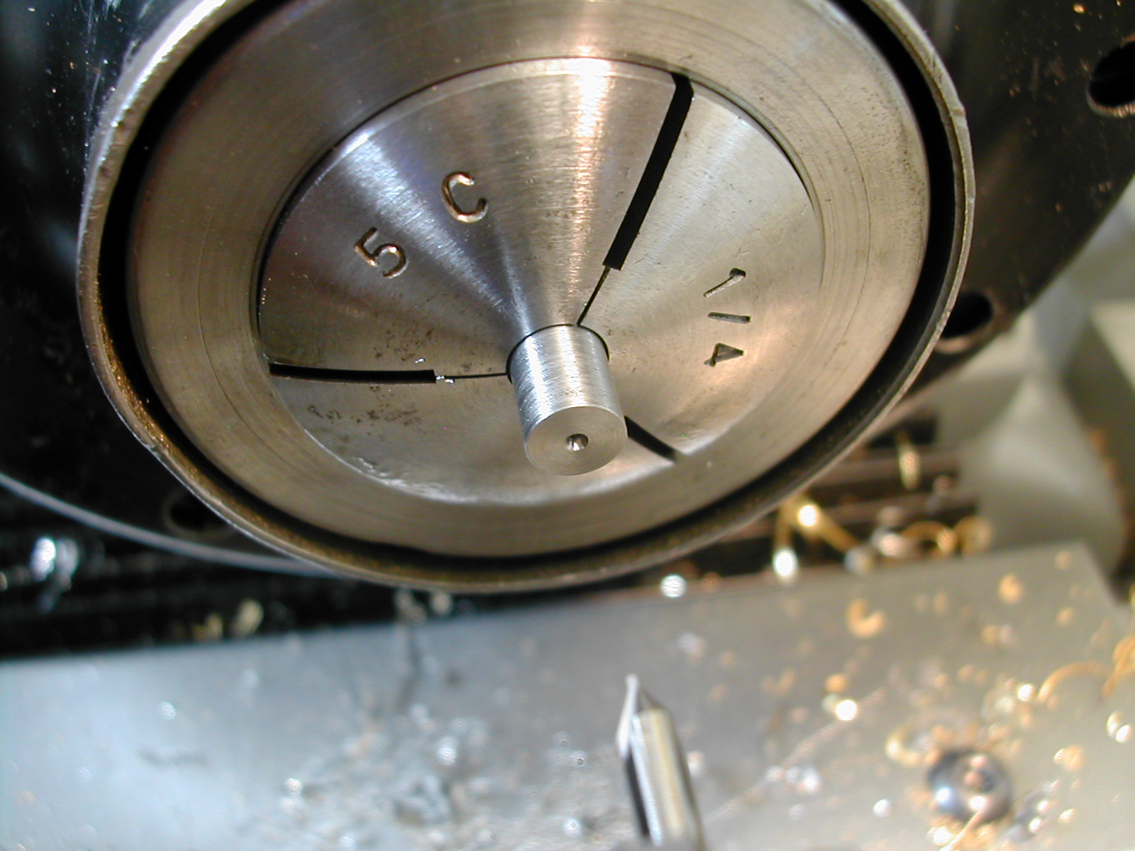 With the 2″ piece close chucked in a collet, I faced and center drilled one end with a #00 center drill. This will become the #6-32 threaded end in a few more steps.
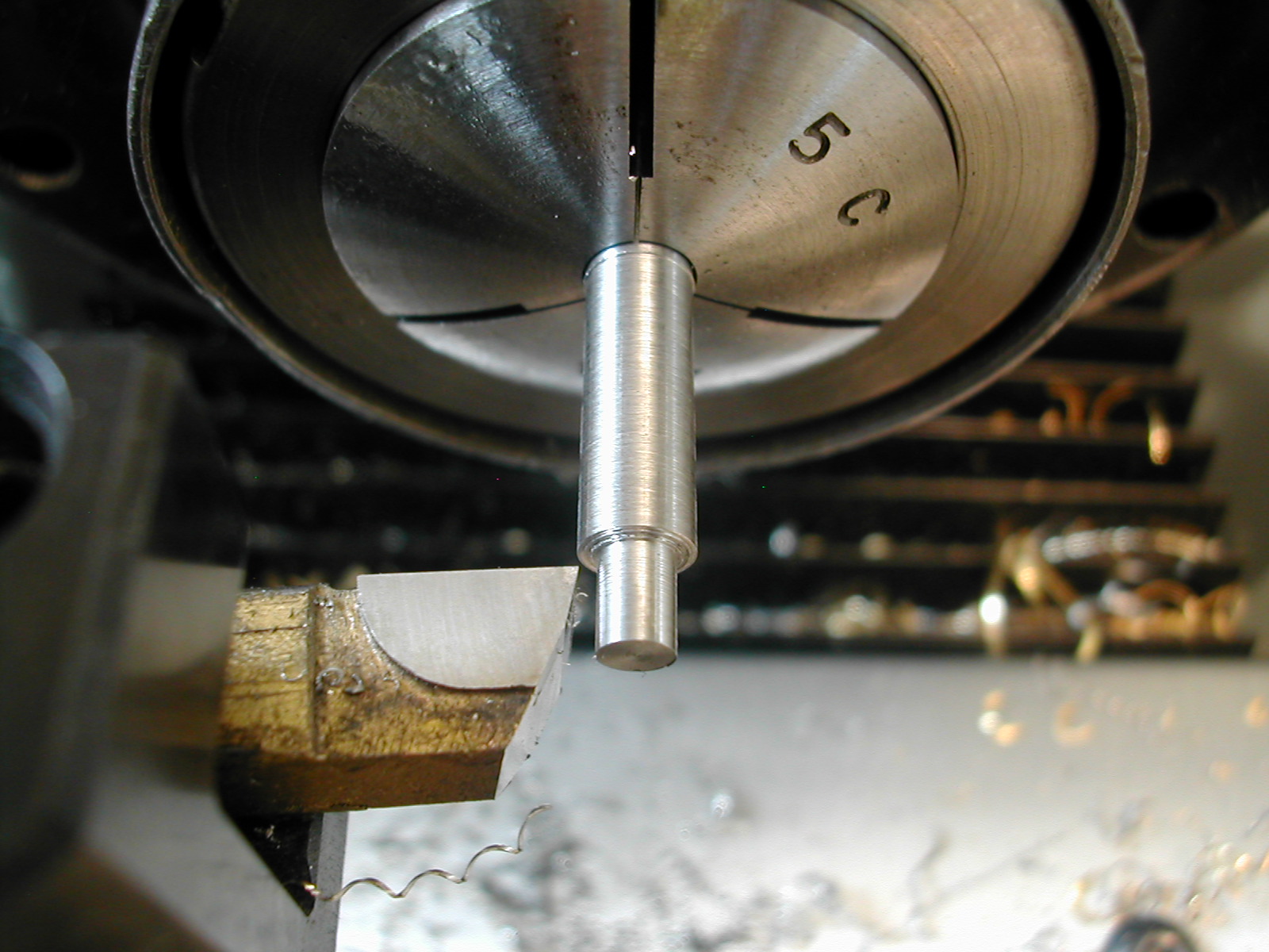 Flipped around, the piece is now faced to the final overall length and work is begun on the ø5/32″ diameter section. This was roughed down to 0.160″ in 1/4″ sections.
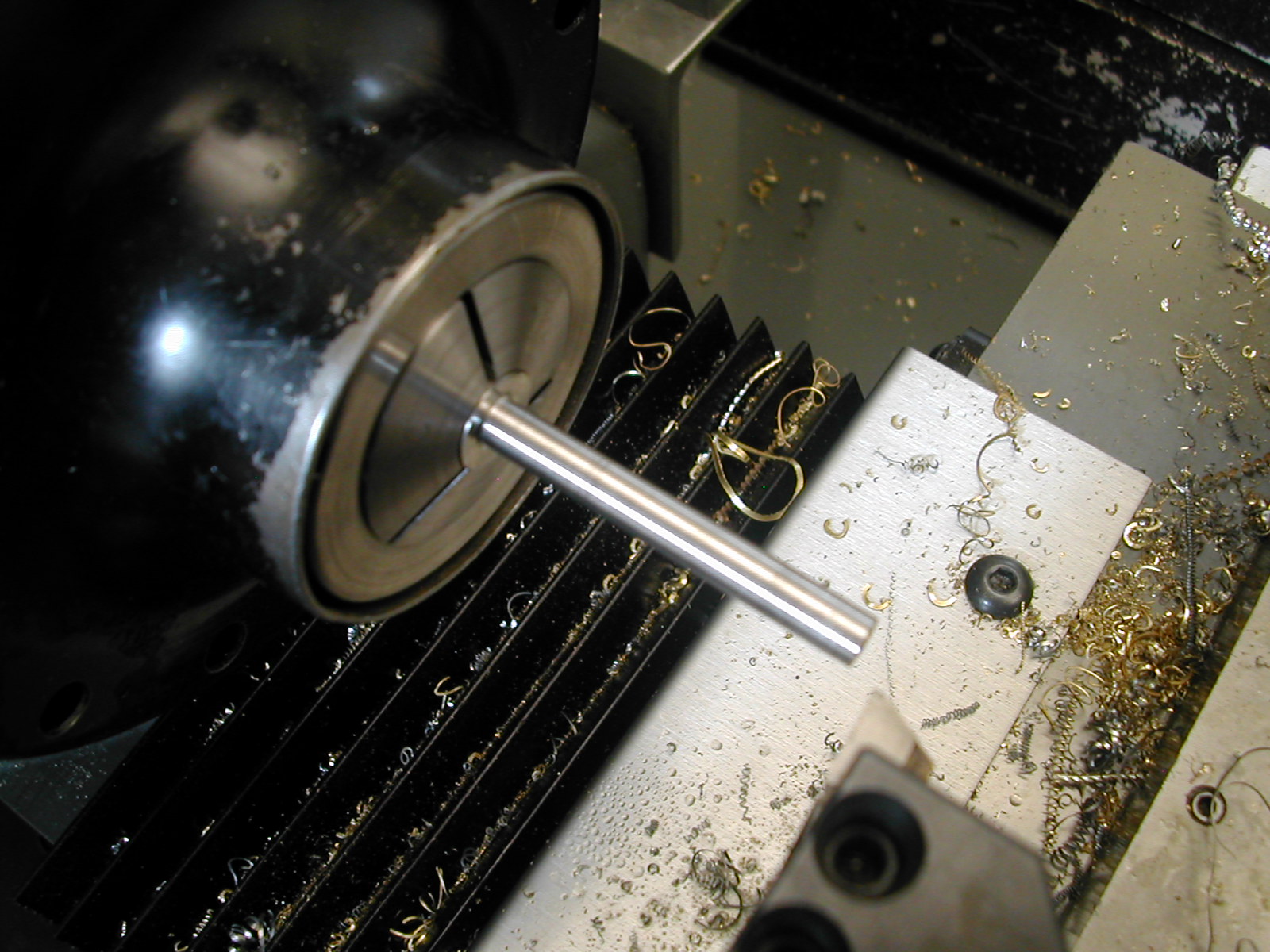
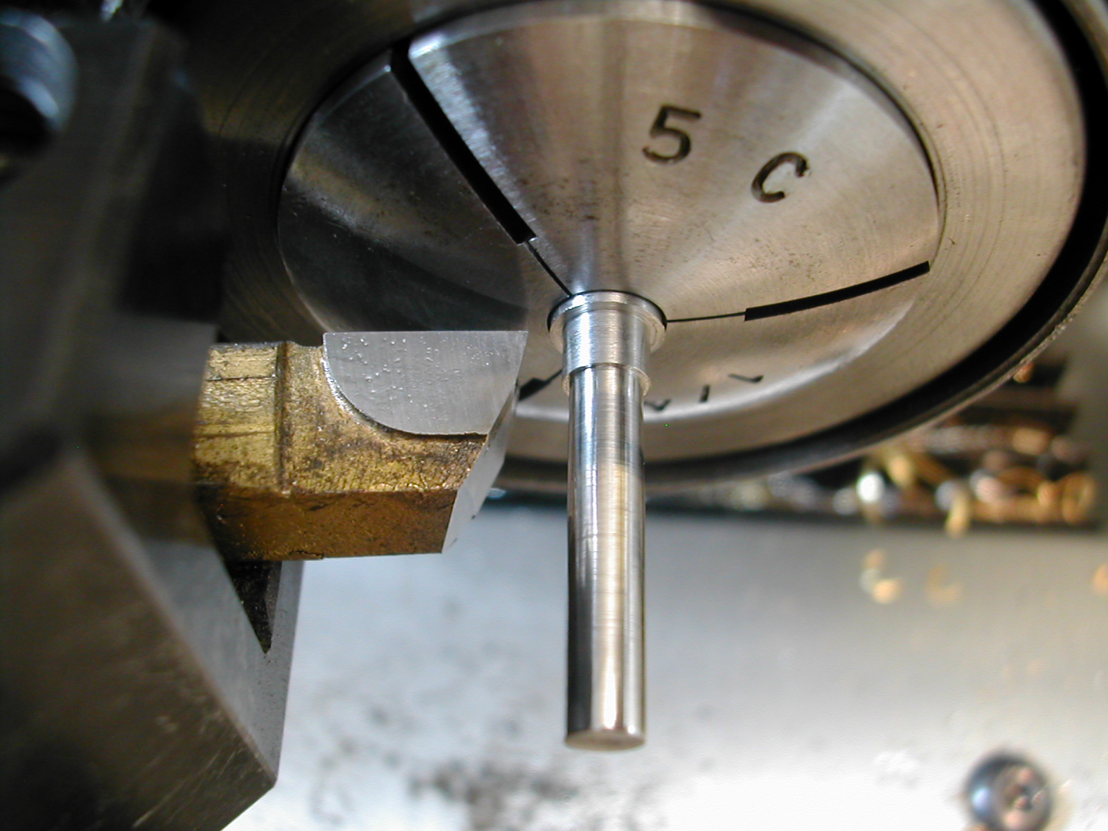 A finish cut was taken on the whole length of the ø5/32″ section and it was fit to the bushing in the Tool Holder Head. The 3/16″ shoulder was next turned long and to size on the diameter.
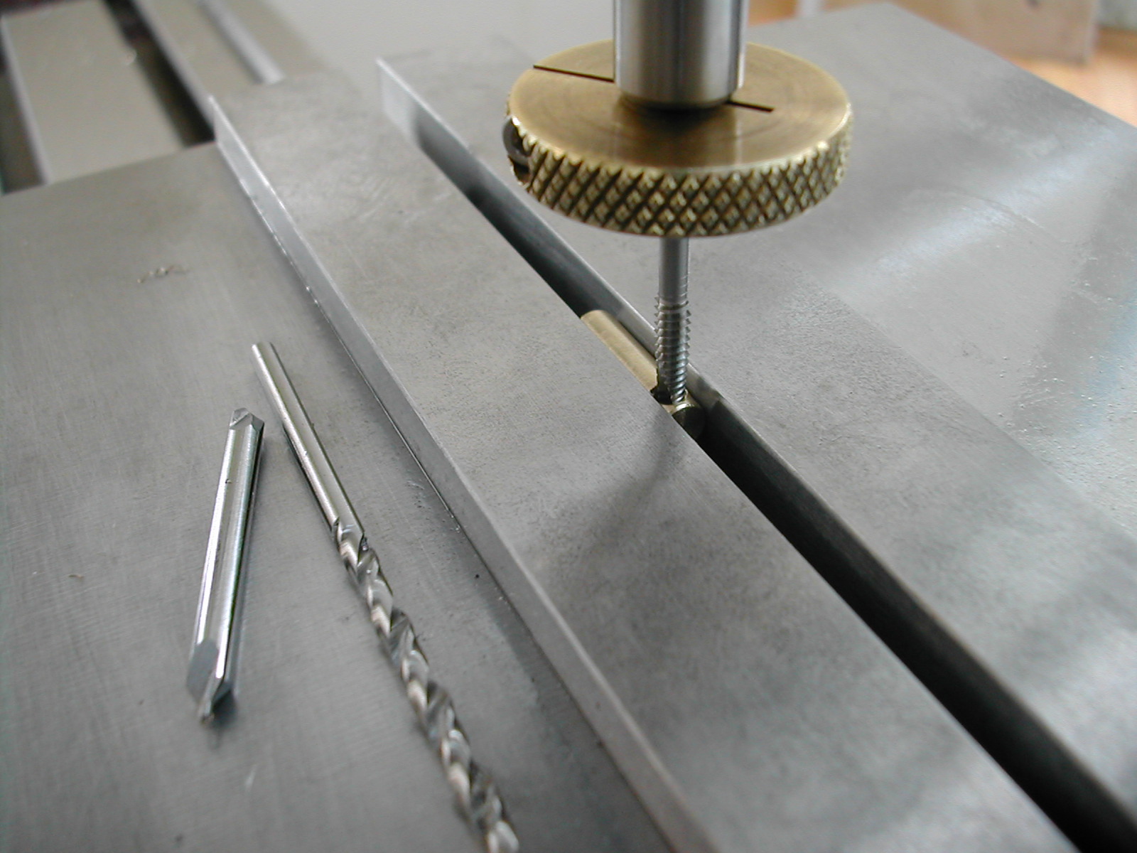
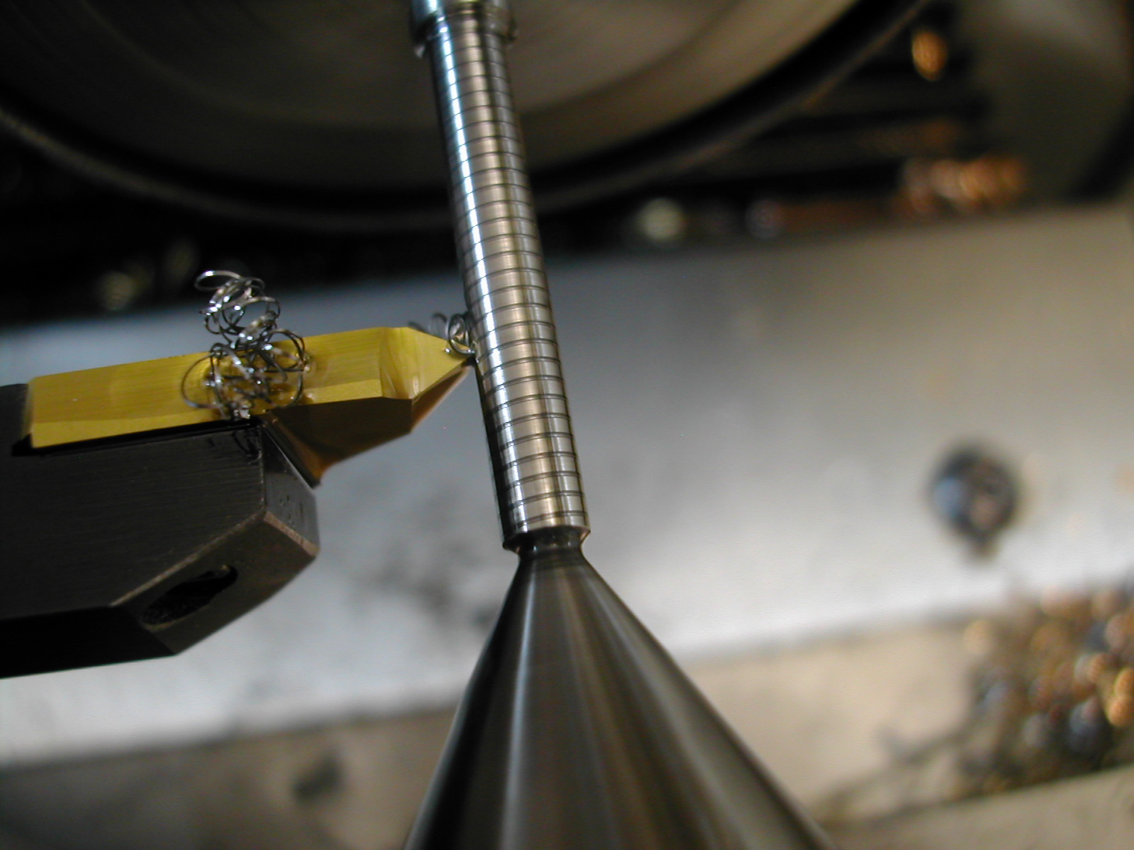 With the upper portion finished, the part was flipped and a live center engaged in the pre-drilled center. The threaded section was turned to ø0.136″ in a stepwise fashion. Here, I’ve just started threading.
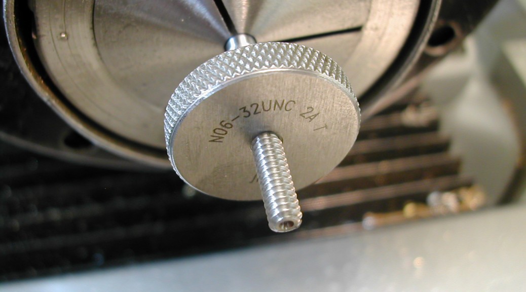
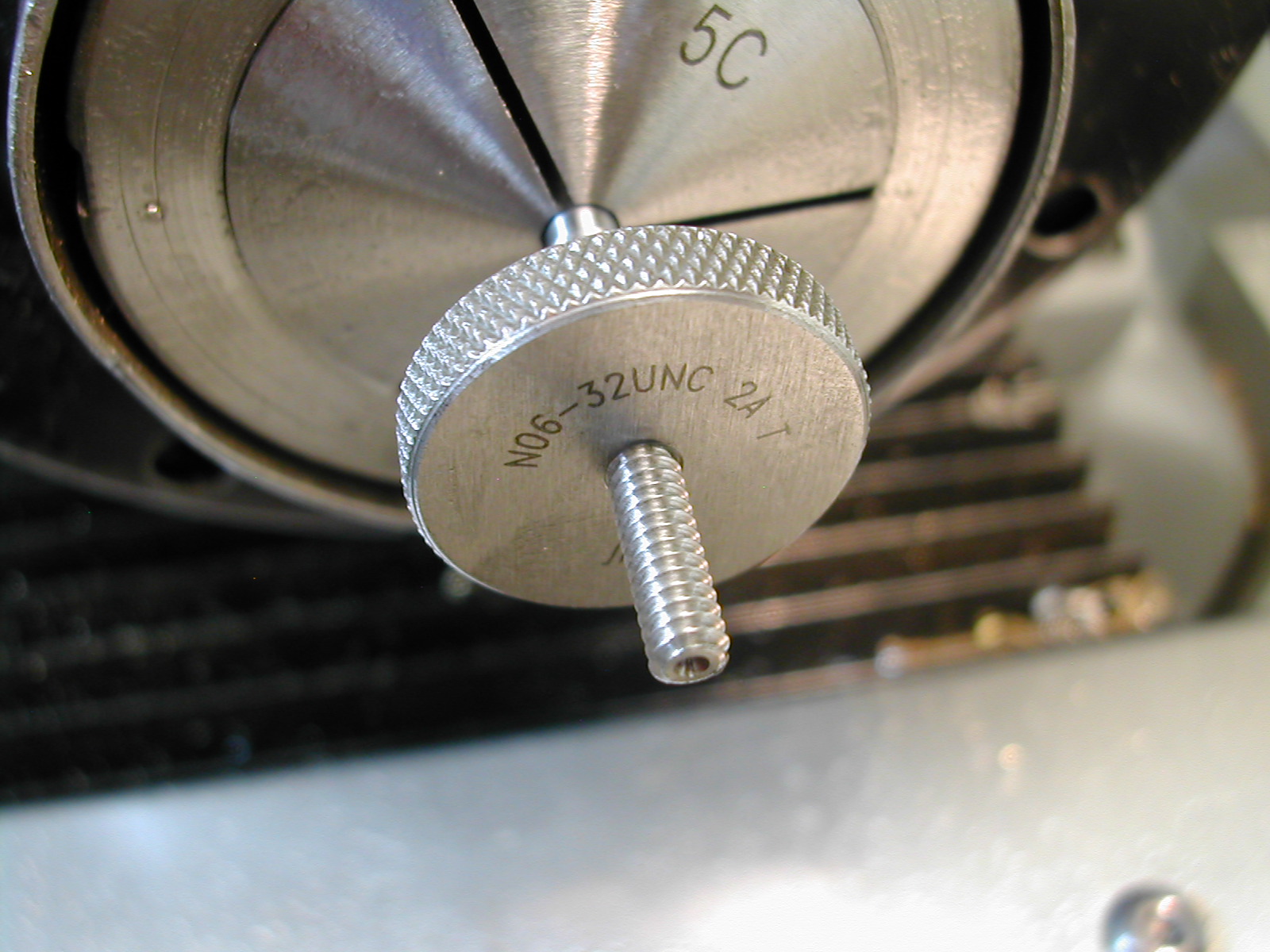 Not wanting to bow the spindly part, threading was accomplished at 0.001″ per pass and therefore took quite a while. However, I ended up with a perfect thread the whole length so it was worth it. Checked in the nut made earlier, there is no play but the screw still turns freely.
Disclaimer and License
All material, including the CAD drawings, relating to the construction of the Cut Knurling Tool presented on this site is free to use any way you see fit. However, no guarantees are made regarding the accuracy or correctness of the material presented here.
Downloads
(CAD drawings are in SolidWorks 2013 Format)