
- Cut Knurling Tool Overview
- Tool Holder Arm and Head
- Spindle and Wheel Nut
- Small and Large Gears
- Spindle Housing
- Locking Levers
- Height Adjustment Mechanism
- Cut Knurling Tool Final Assembly
Final Assembly
 I began the final assembly with the fitting of the levers. First the height adjust lock lever was installed and a measurement was taken for a test shim. I added an extra 0.01″ to account for the fact that the lever was not tightened at this point. A quick test shim was made without the locking lip.
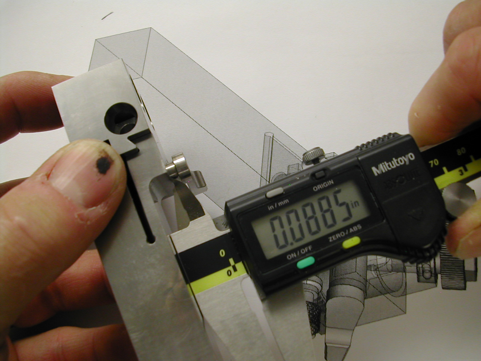
 The test shim was installed and the lever tightened as shown in the photo. I want the tightened lever to be approximately parallel with the shank and based on this photo it should turn about 135° more.
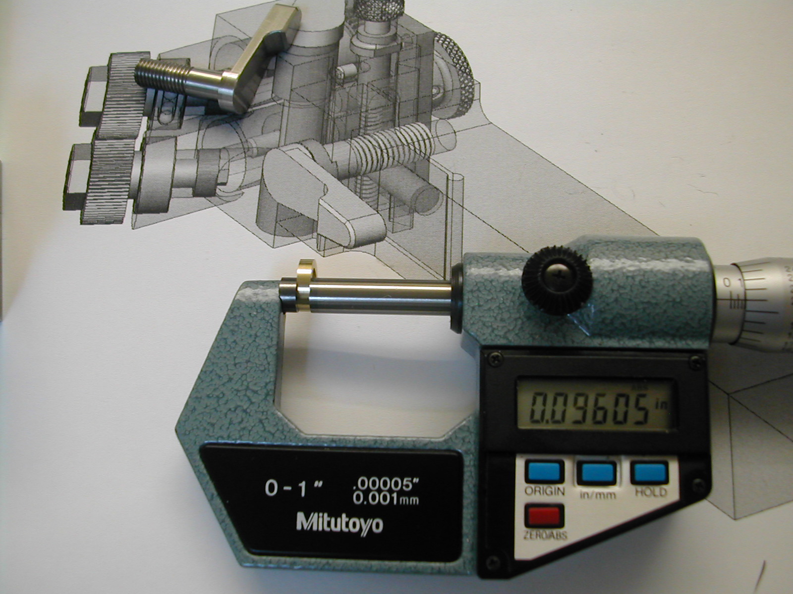 The test shim was removed and measured at 0.0963″. So the amount to be removed from the shim is the number of turns * the pitch of the screw: 135/360 / 28 = 0.0134″
That gave me an adjusted washer thickness of 0.083″. A new blank for the locking lever washer, Detail 16, was then turned with an overall thickness of 0.083″ + 0.031″ for the anti-rotation tab.
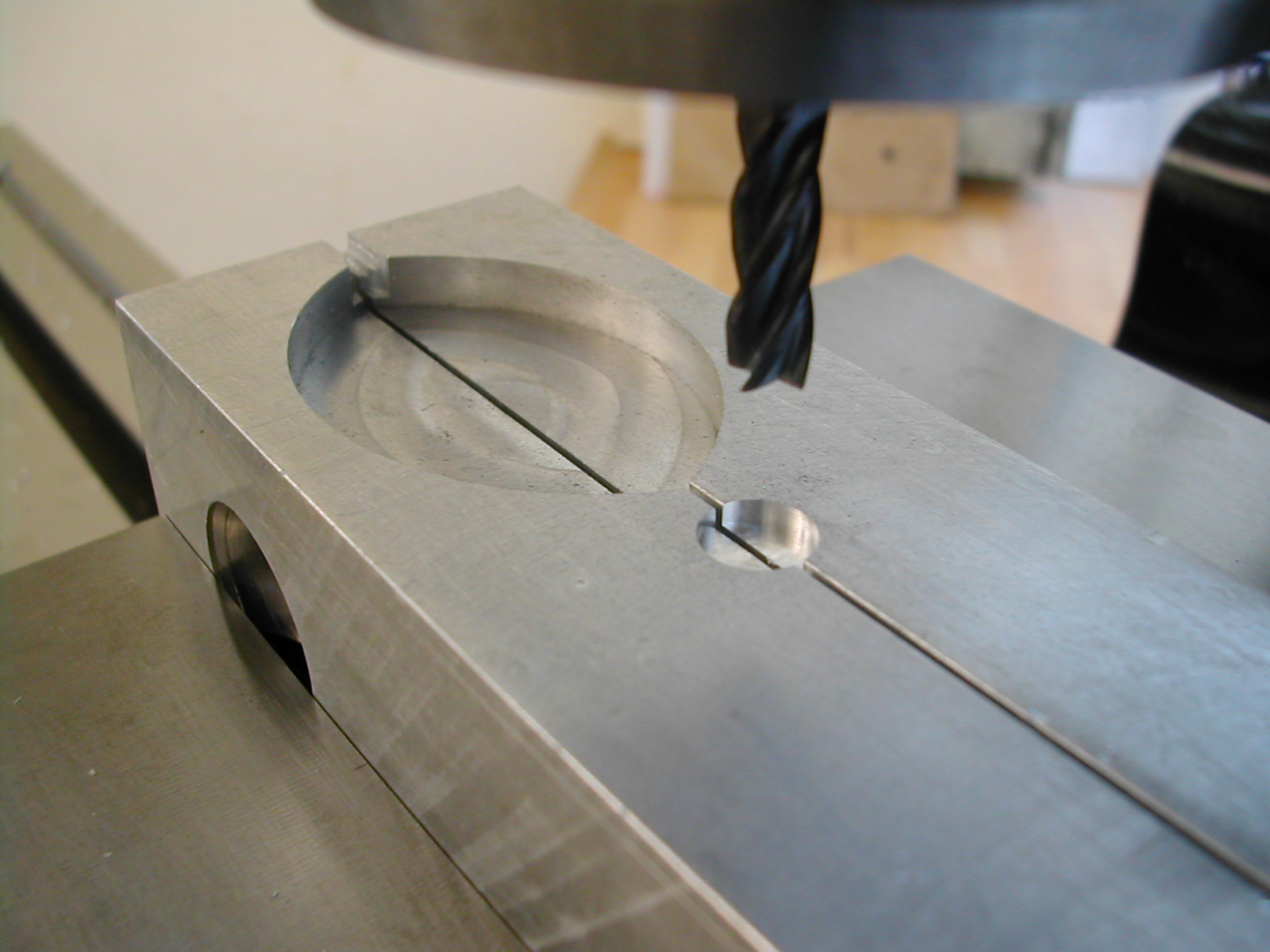 To finish the locking lever washer, I bored a ø0.375″ hole 0.083″ deep in my soft jaws on the mill. The jaws were clamped on a small piece of strapping to keep them slightly apart for this operation.
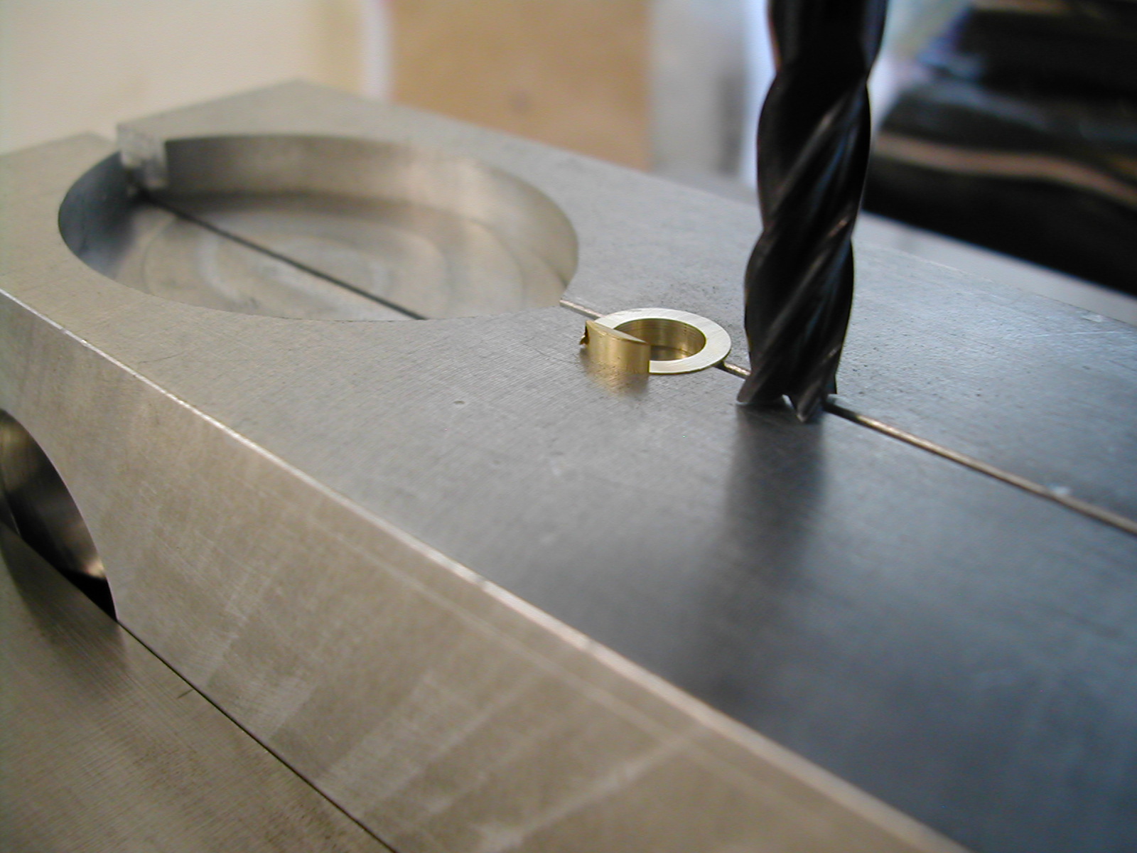 The locking lever washer blank was then clamped in the pocket and the anti-rotation tab was milled 0.031″ deep leaving the washer portion 0.083″ thick.
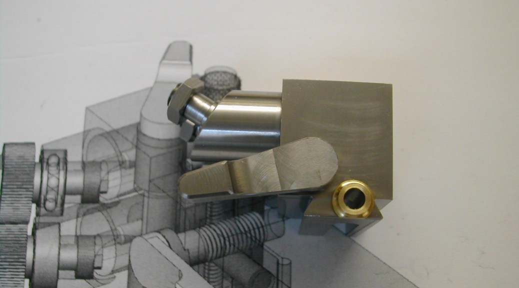
 Here is the lever in its final locked position.
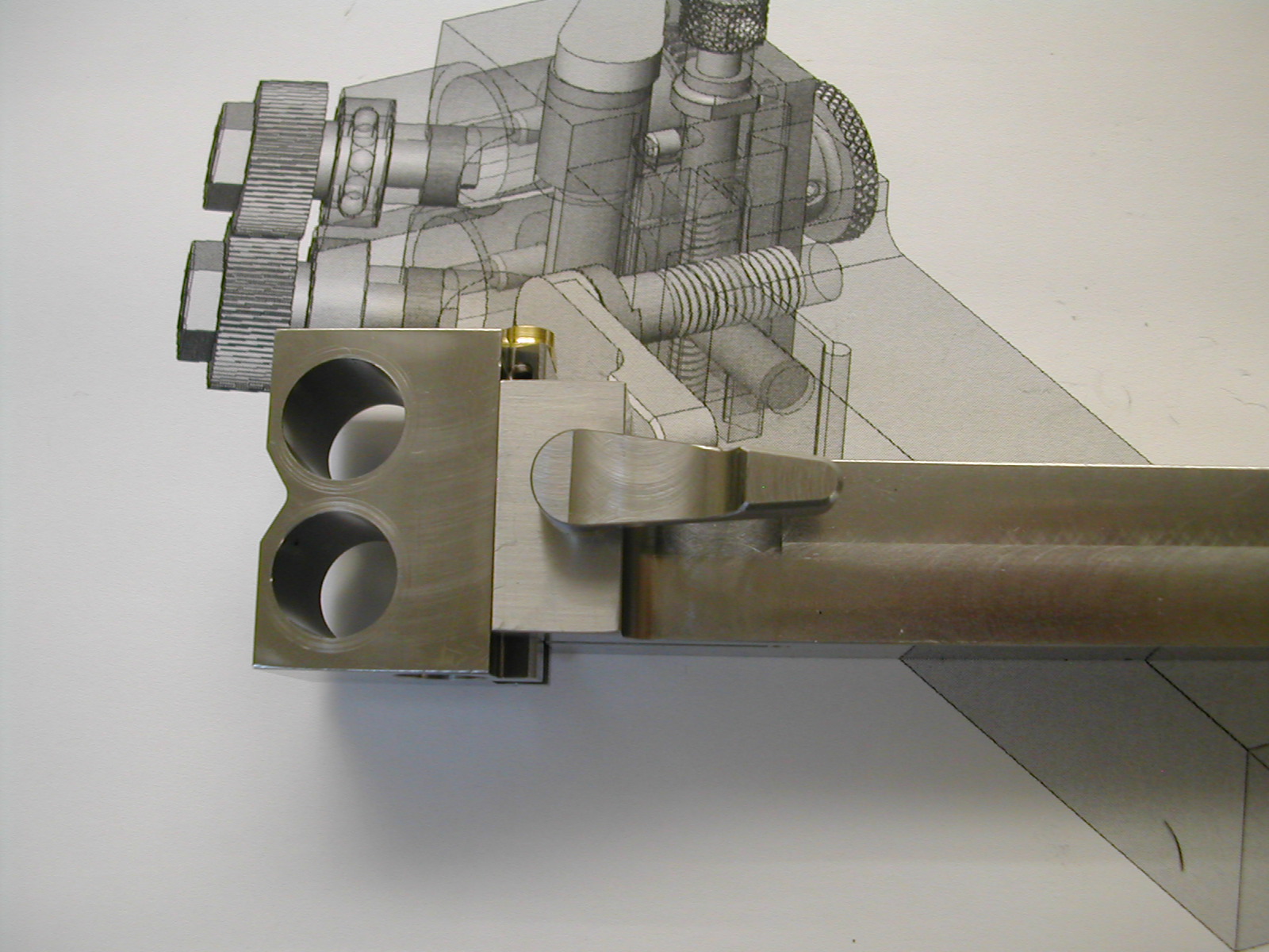
 Next, the spindles were temporarily inserted, and the bottom cotter and the lengthened top cotter were installed with the height locking screw. I wanted the lock and unlocked positions for this lever to be located above the body with the full lock position to be with the right side of the lever aligned with the upper right corner of the body block. Based on this image, I need to rotate the lever an additional 142°.
 Using the same math as before, I removed 142/360 / 28 = 0.0141″ from the end of the top cotter. I chose not to add the coping cut at the top of the cotter as I felt that it was mostly hidden by the lever and the reduced bearing surface could cause early failure.
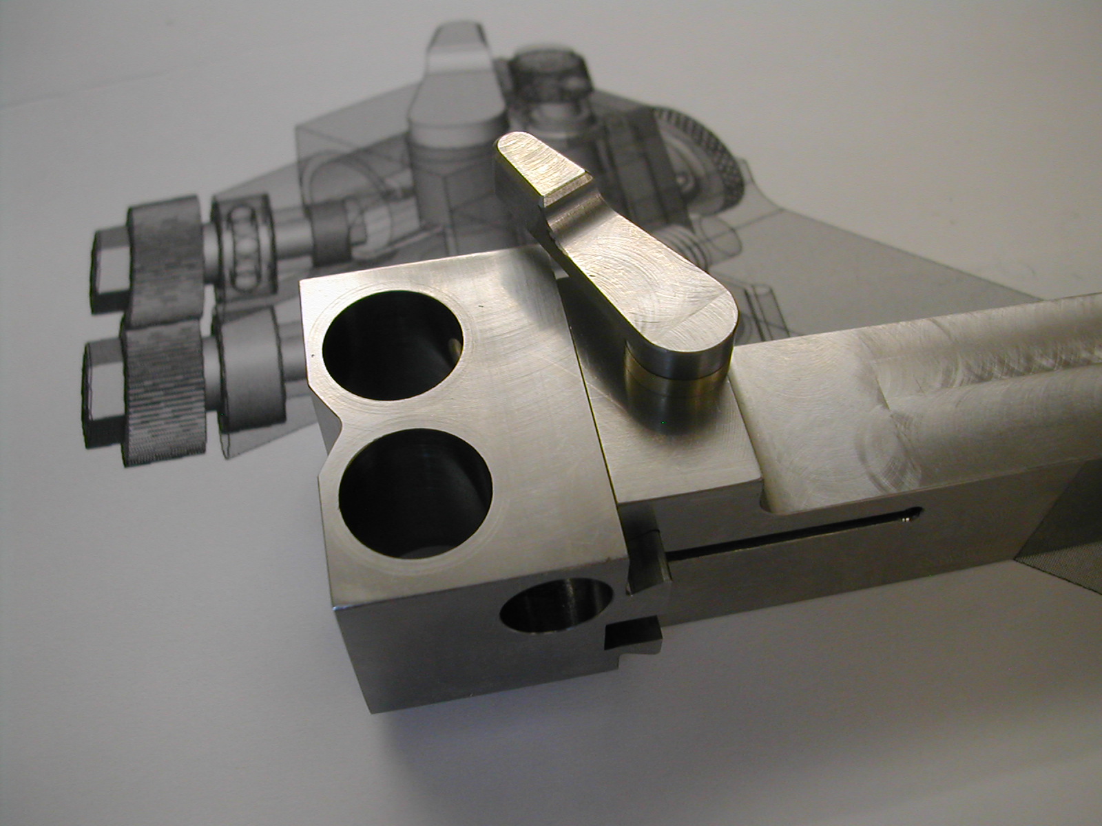
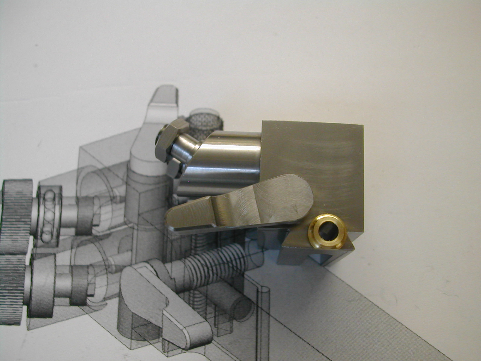
 Here is the cotter locking lever in its final locked position.
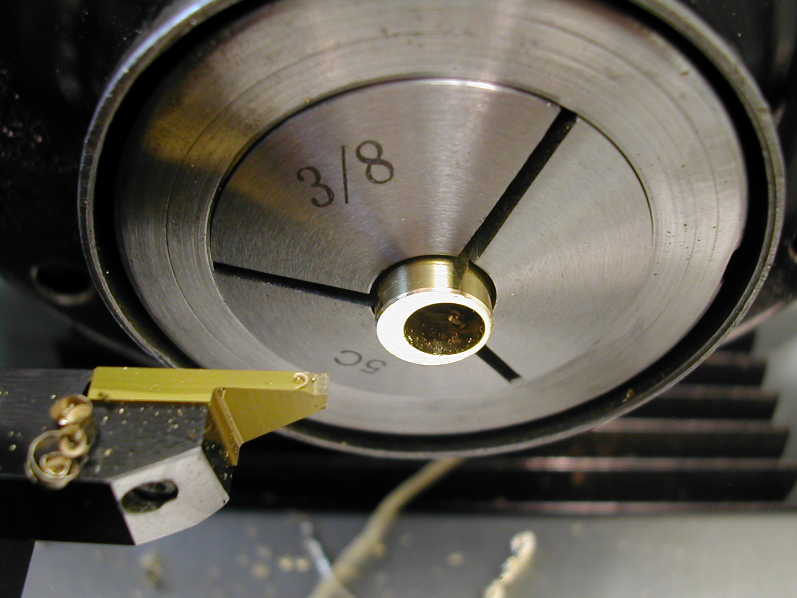
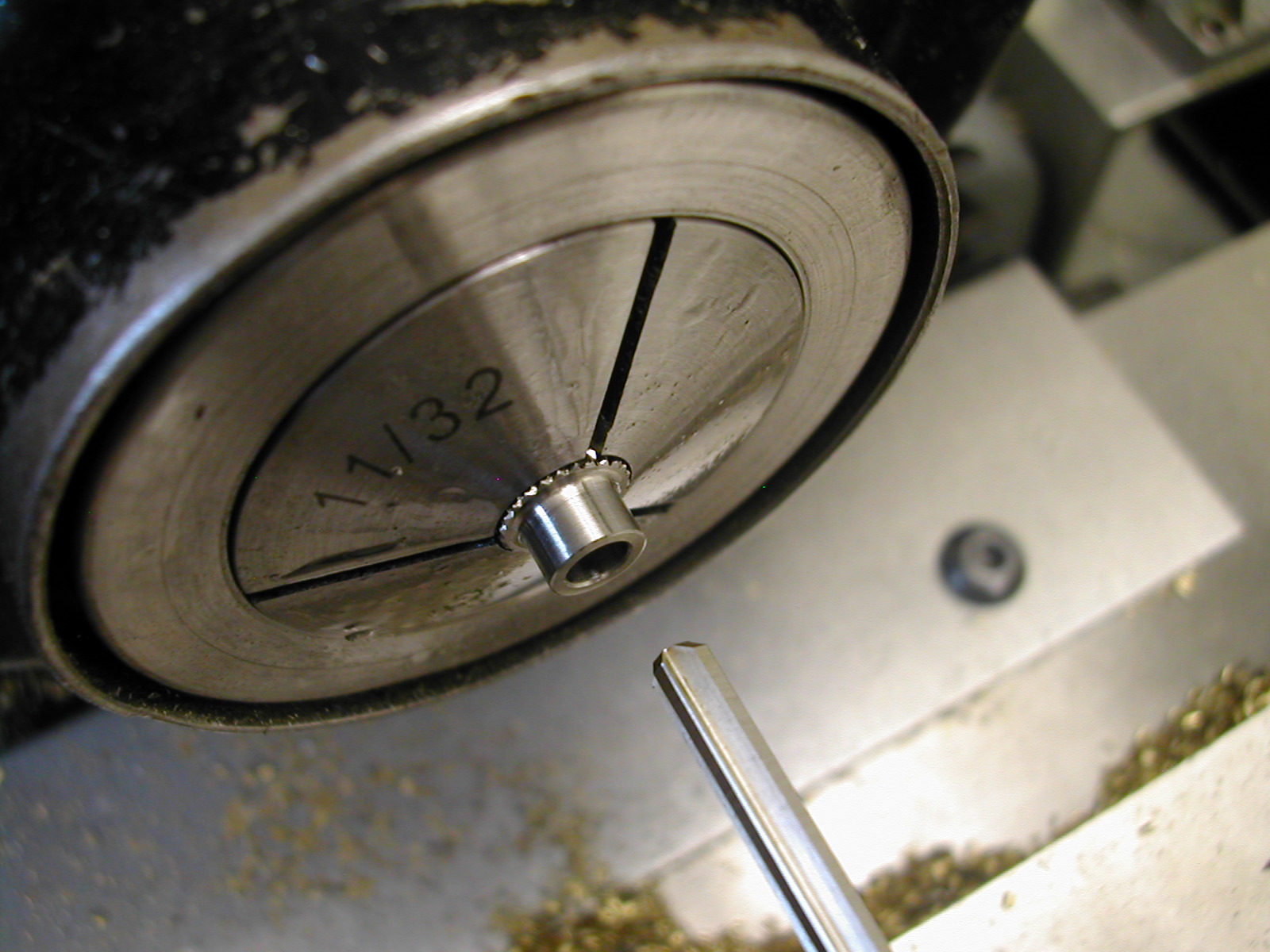
At this point, I temporarily assembled the knurler with some temporary knobs so that I could use it to knurl details 12 and 21. Here, I’m starting on Detail 12, the Height Screw Knob.
 The diameter is 5/16″ nominal and this was adjusted based on the knurls I was using. The circumference of the nominal size would be 0.3125″ * π = 0.98175″. This length using 40LPI knurls would produce 0.91875″ * 40 = 39.2699 lines. Therefore, to get rid of any partial knurl lines the diameter should be adjusted to: 39 / 40 / π = 0.310″. Many say this adjustment is not needed when knurling but it takes only seconds to calculate and it certainly can’t hurt.
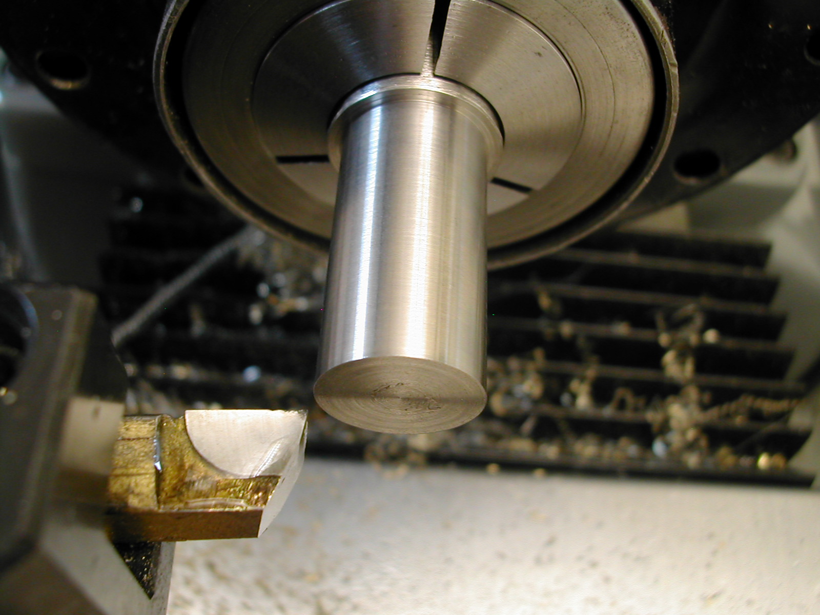
 The end shoulder is turned and the oval top hand filed. The knob is then parted off and faced to the finished length.
 The bottom shoulder was turned and then the end was center drilled in preparation for drilling the shaft hole.
 The shaft hole was drilled and reamed 5/32″ to fit the height adjustment screw.
 Finally the knob was tapped #3-48 for the socket head set screw to lock it in place.
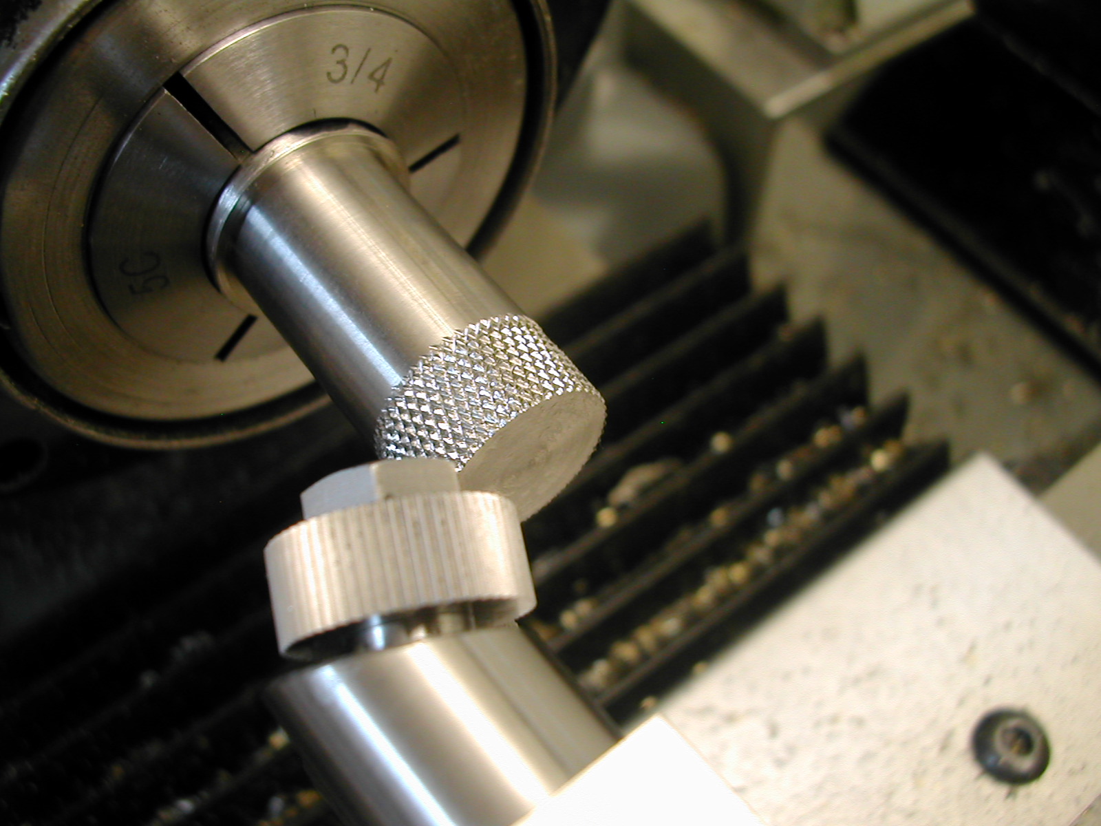
 Next, I rough turned the OD for the Spindle Adjustment Knob, Detail 21. The knurled portion is specified as 0.625″ but again I adjusted this based on my 40 LPI knurls. The actual diameter I turned was 78 / 40 / π = 0.621″
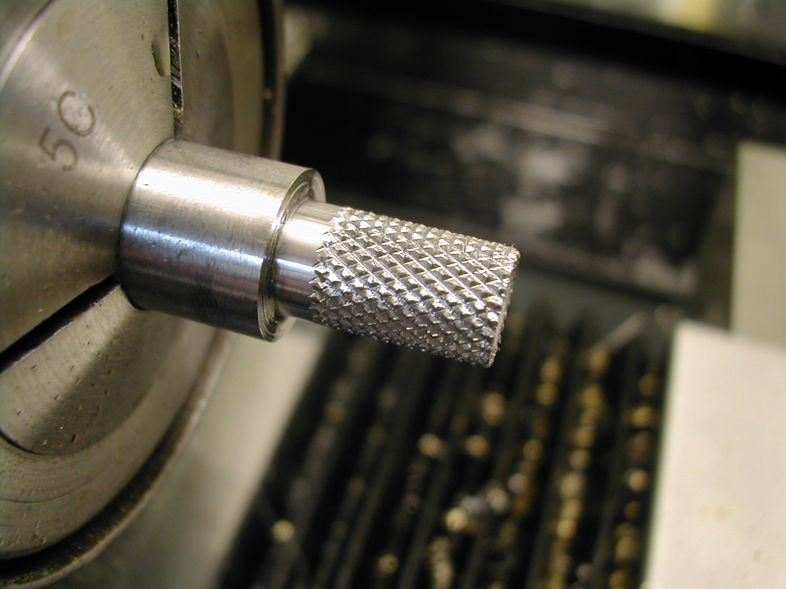
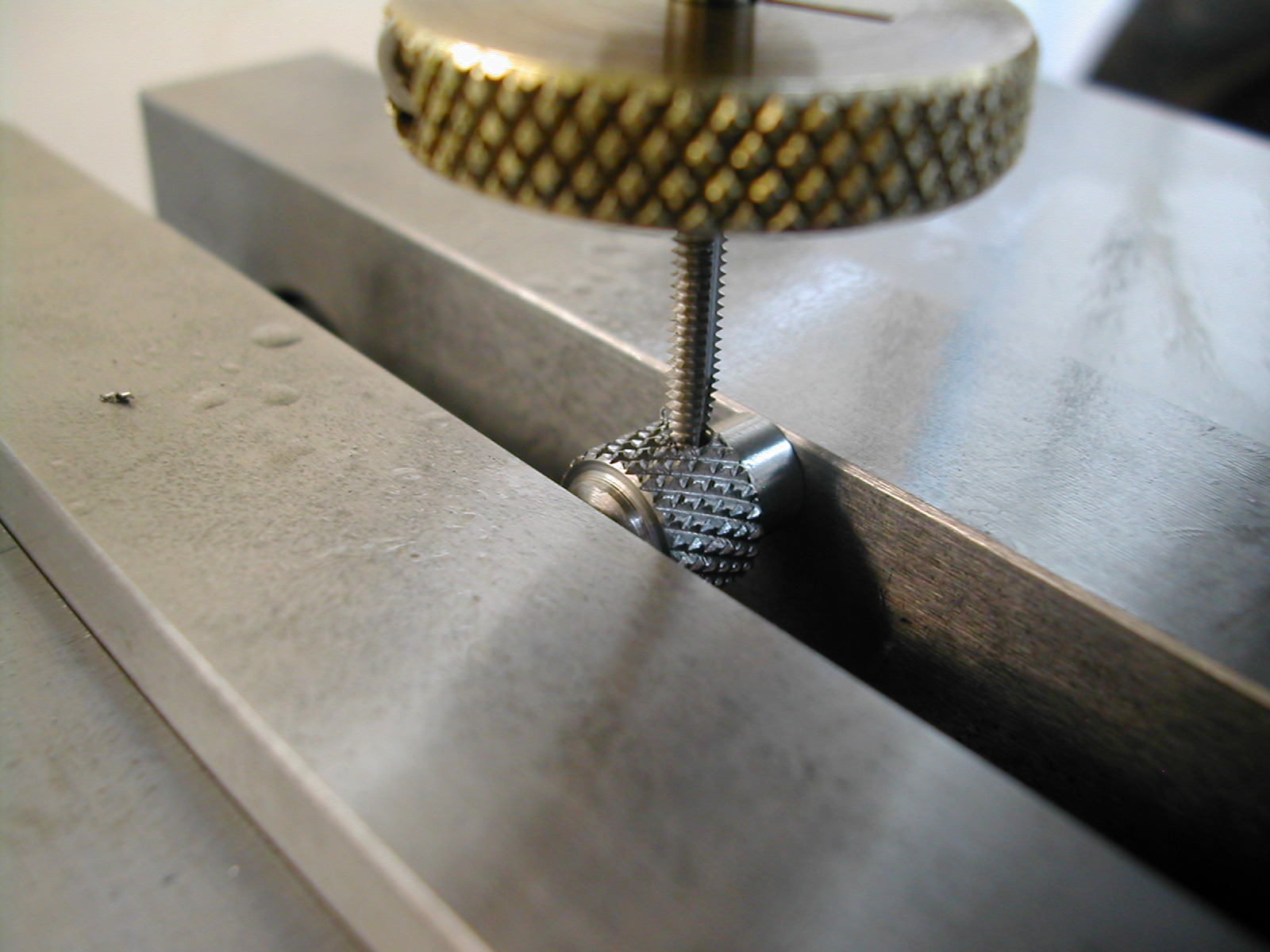
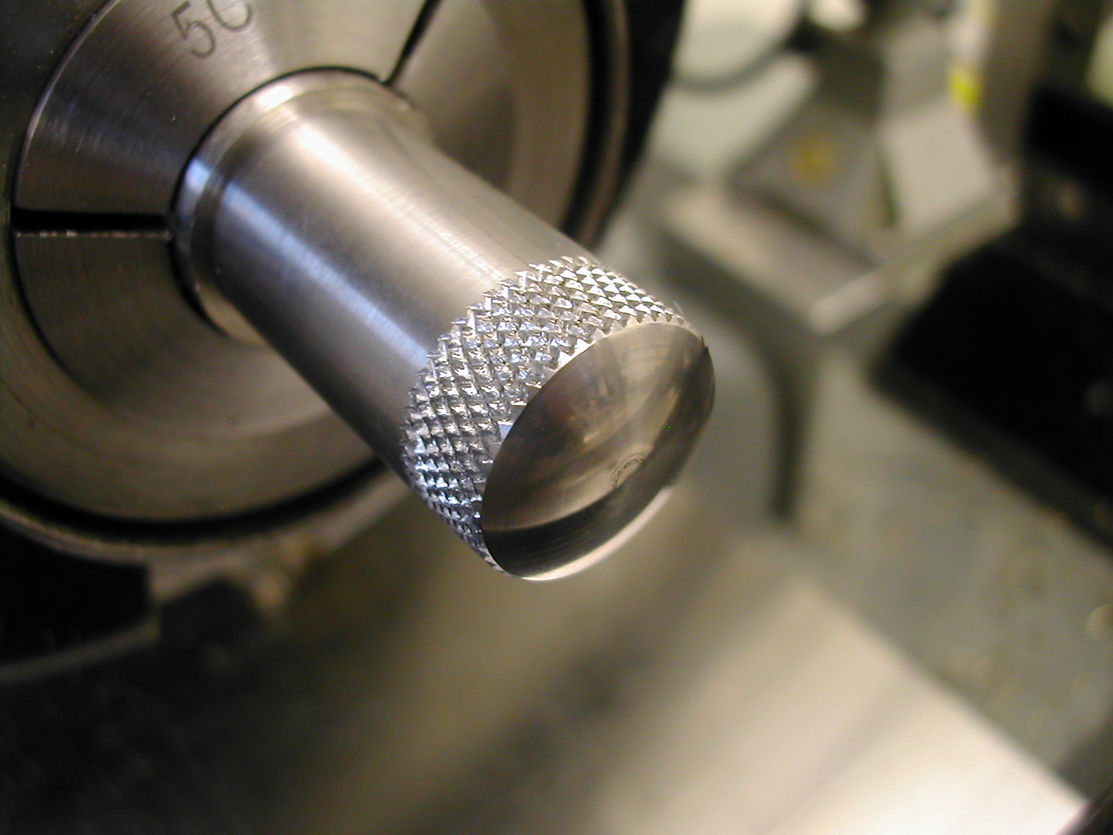
 Here’s the actual knurling taking place. I was really impressed with the quality of the knurls produced with this took given that the material was hardened 17-4 stainless.
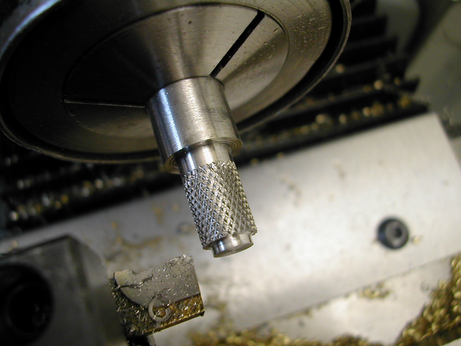
 Here the end embellishment was roughed by hand with a facing tool, the filed and sanded smooth. The rest of the knob was finished much in the same way as the previous one.
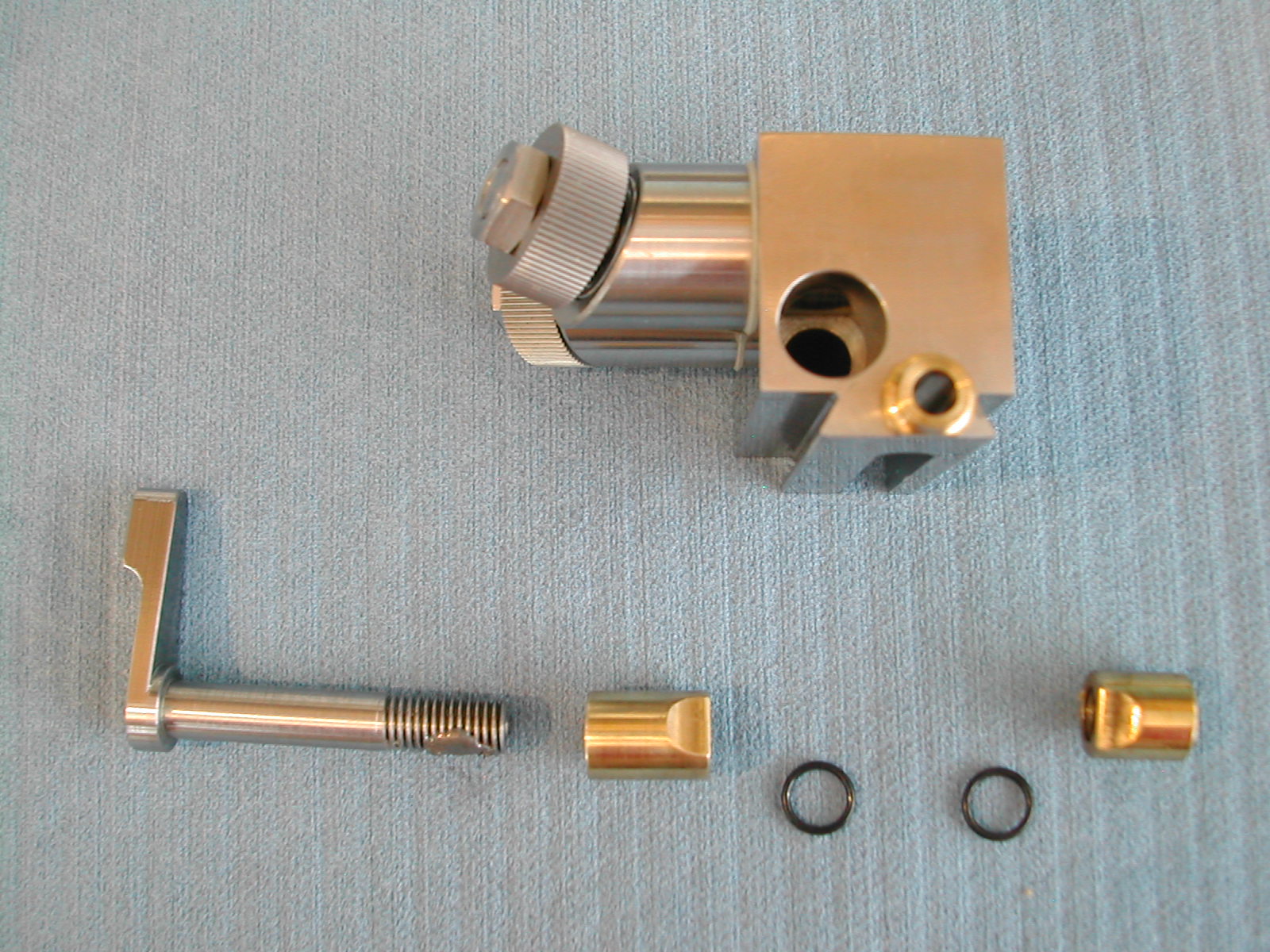
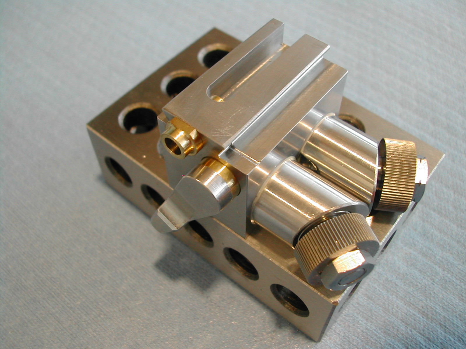
 To start the final assembly, a small amount of lithium grease was applied to the spindle housings before they were inserted into the body.
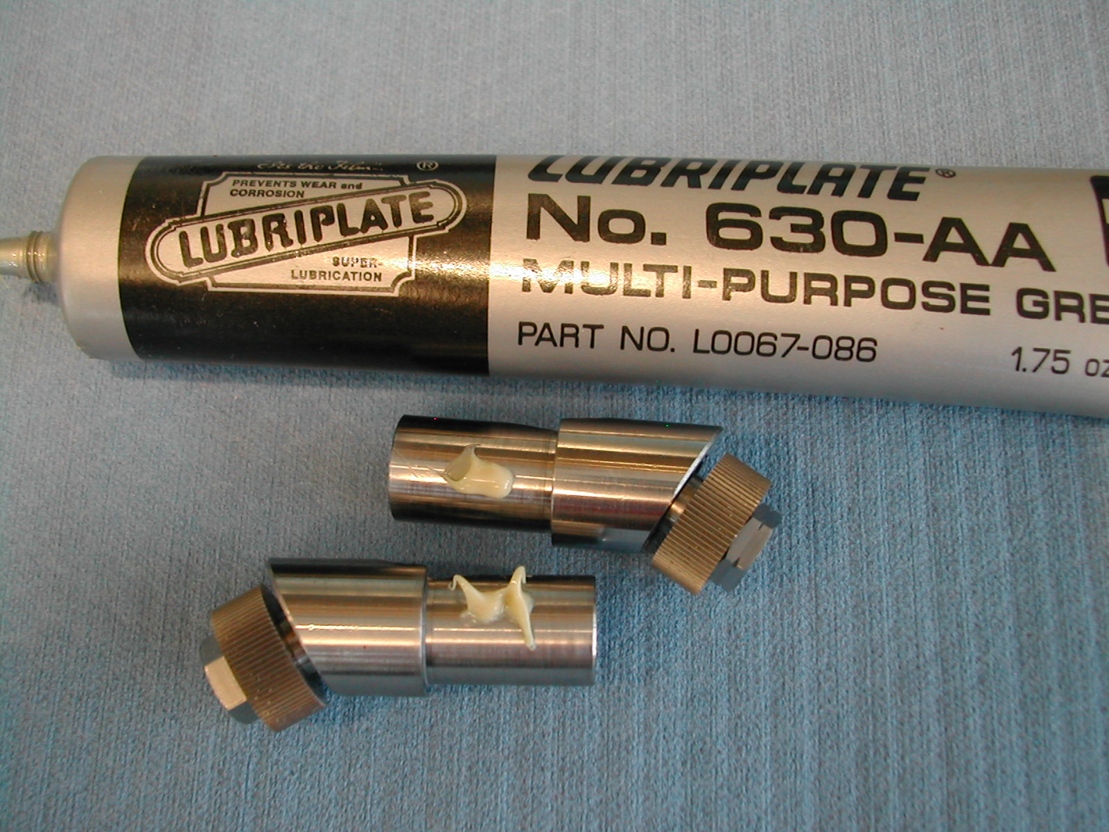
 The cotters were assembled with O-rings at the bottom of the cotter bores. These will act as springs and push the cotters off the housings when the clamp lever is loosened.
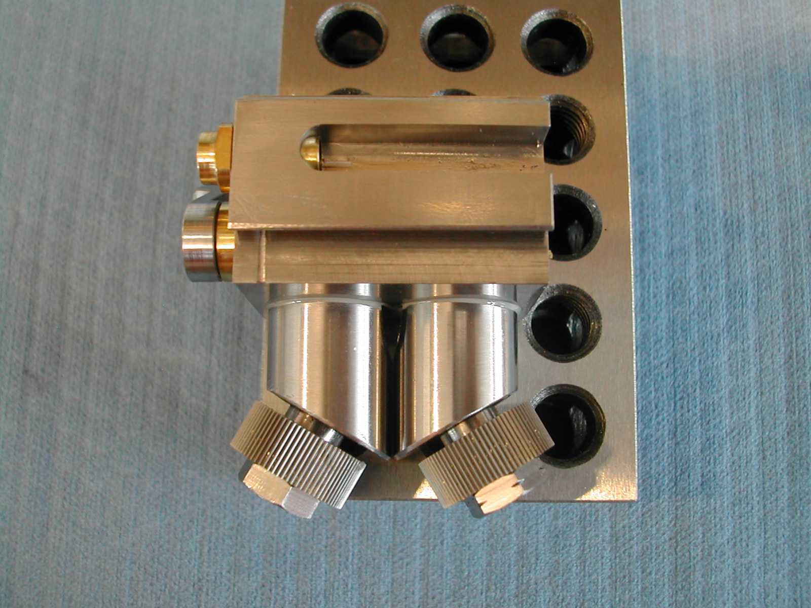 To time the gearing correctly, the spindles were positioned flat with the tool body on a true surface, and the locking cotters were securely tightened.
 This is another view of the spindle positioning operation.
 With the spindles locked, the large and small gears were lubricated with lithium grease and meshed in place.
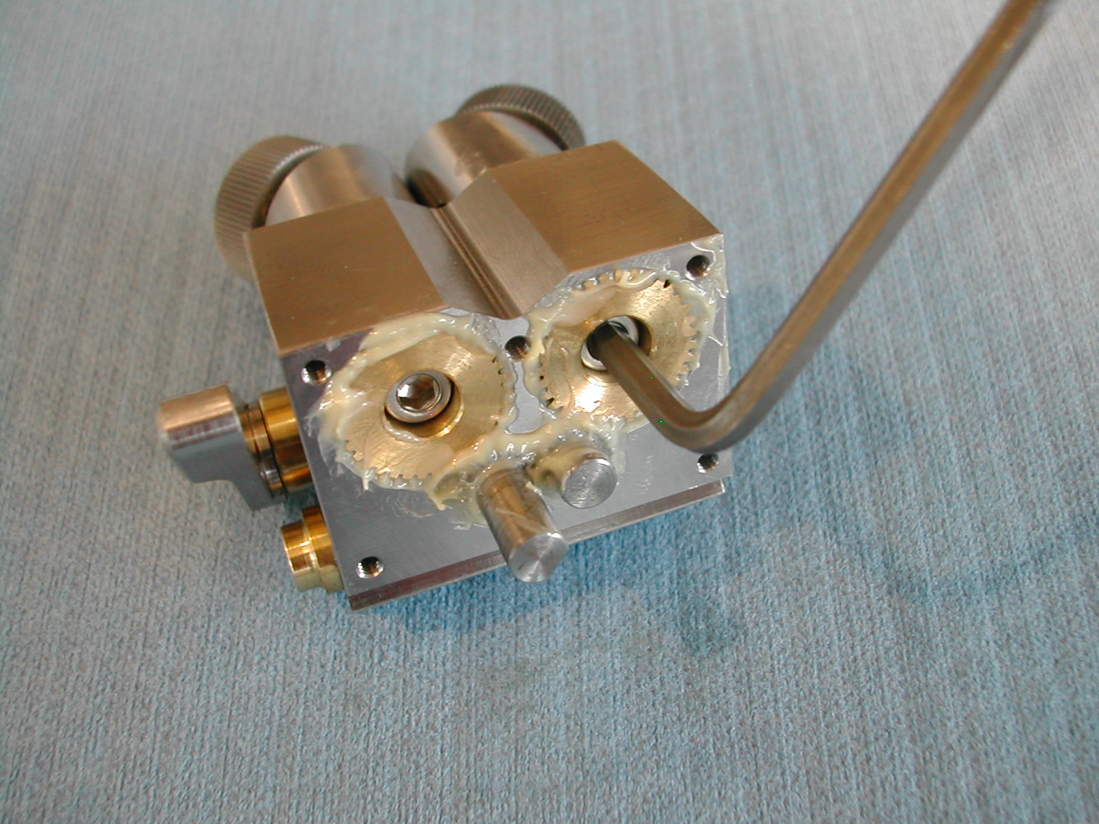 With all of the gears in mesh, and the spindles locked, two #6-32 SHCS to retain the large gears were inserted and tightened.
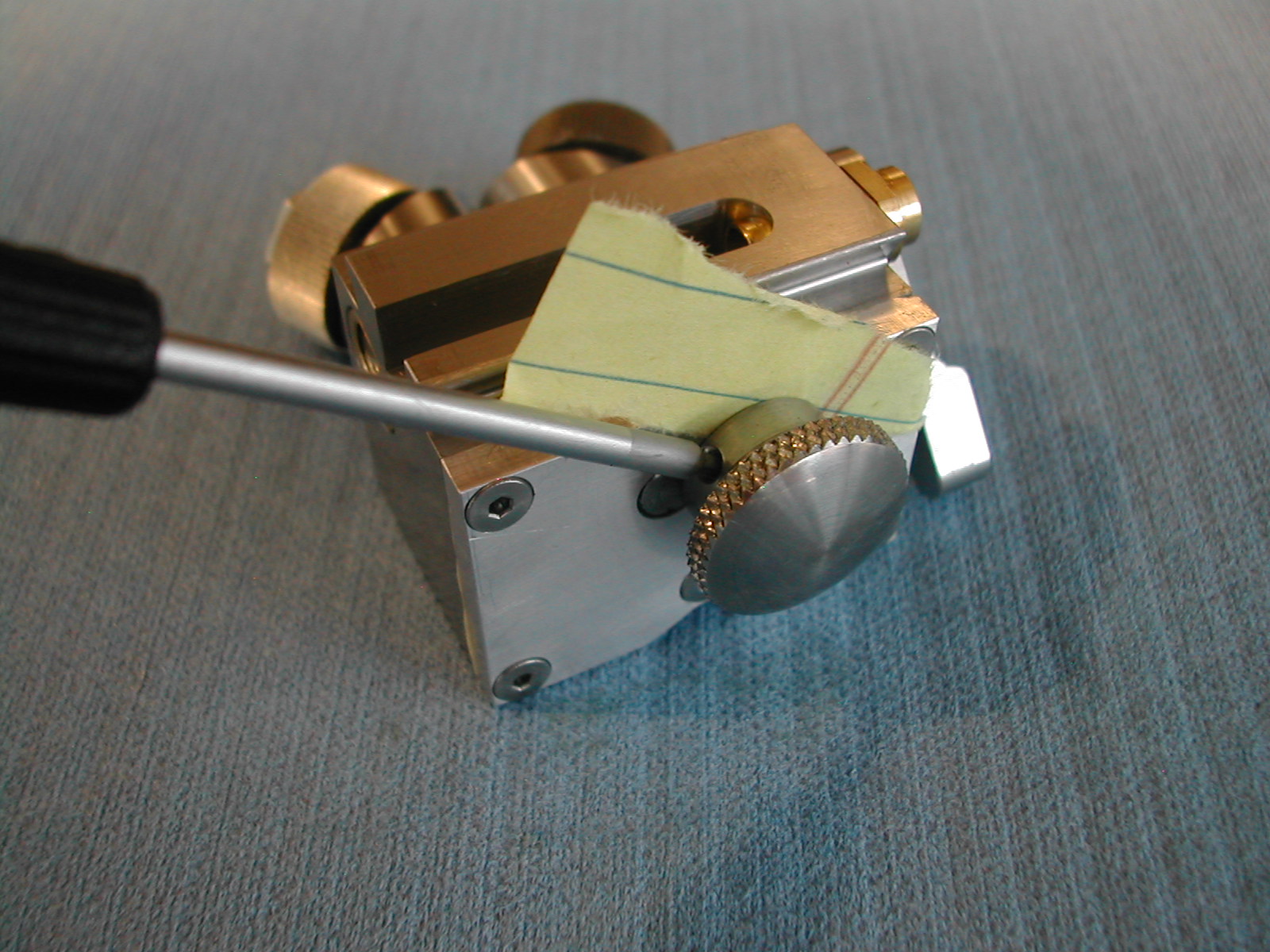 The end cover was installed and the spindle adjustment knob was attached using a piece of paper to provide operating clearance.
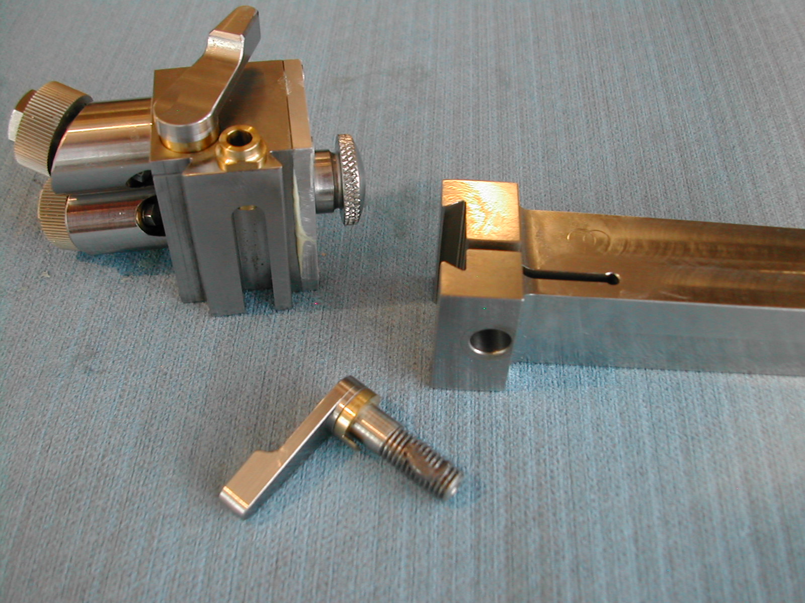 The height lock lever and washer were installed in the tool holder arm with a small amount on anti-seize since both pieces are stainless steel.
 The height adjustment screw and nut are lubricated and inserted in the tool holder head.
 The tool holder body and arm dovetails are mated and the height adjustment knob is locked on the adjustment shaft.
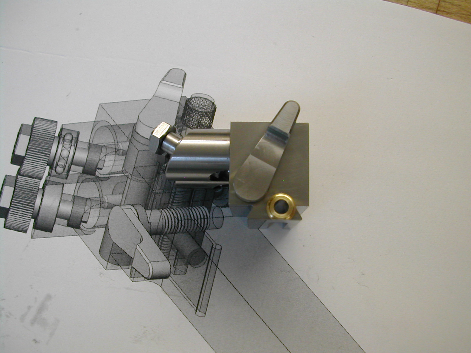
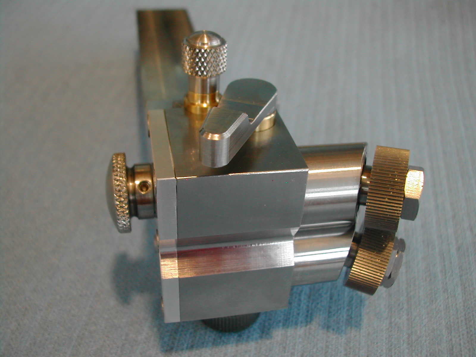
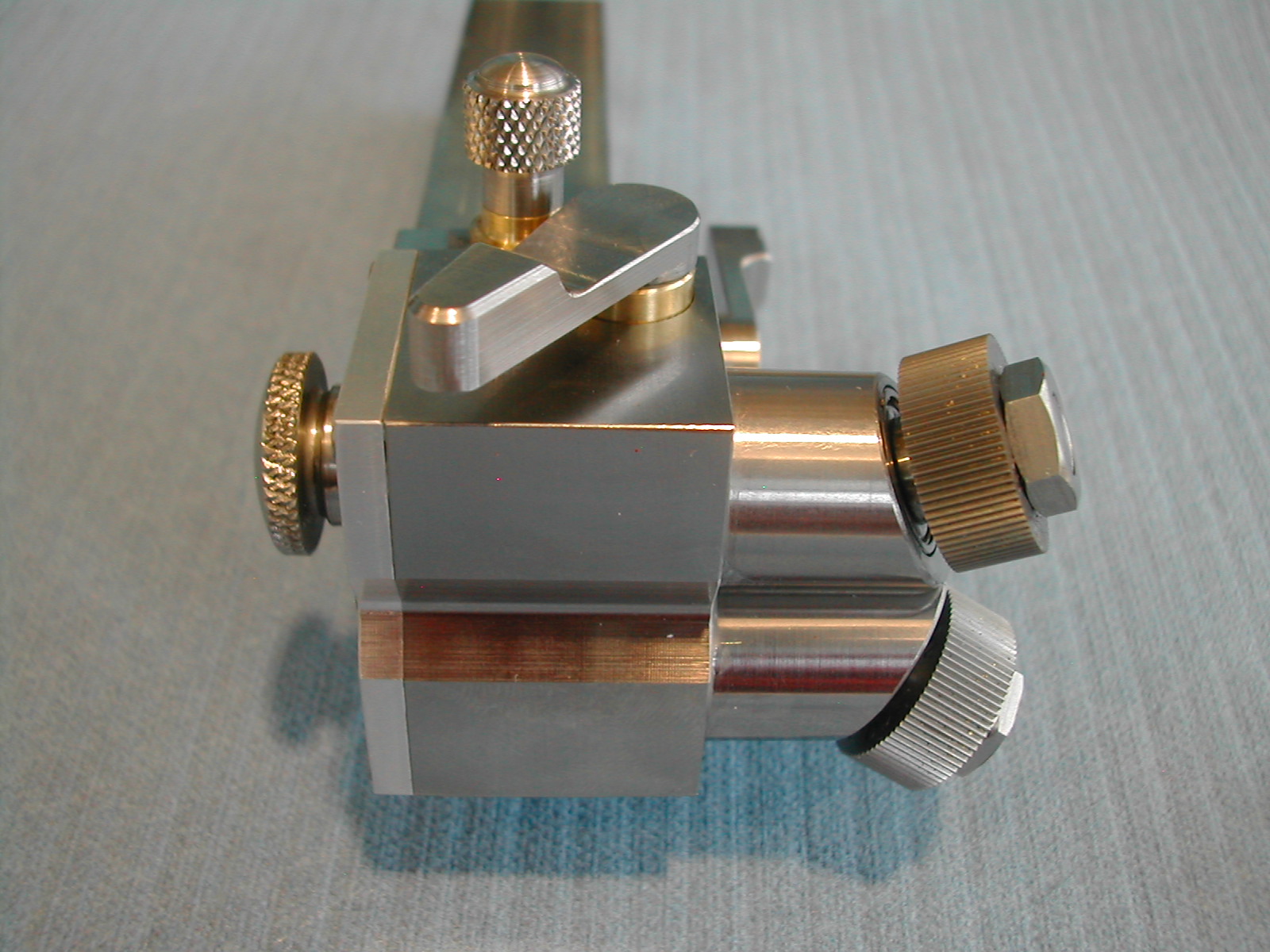
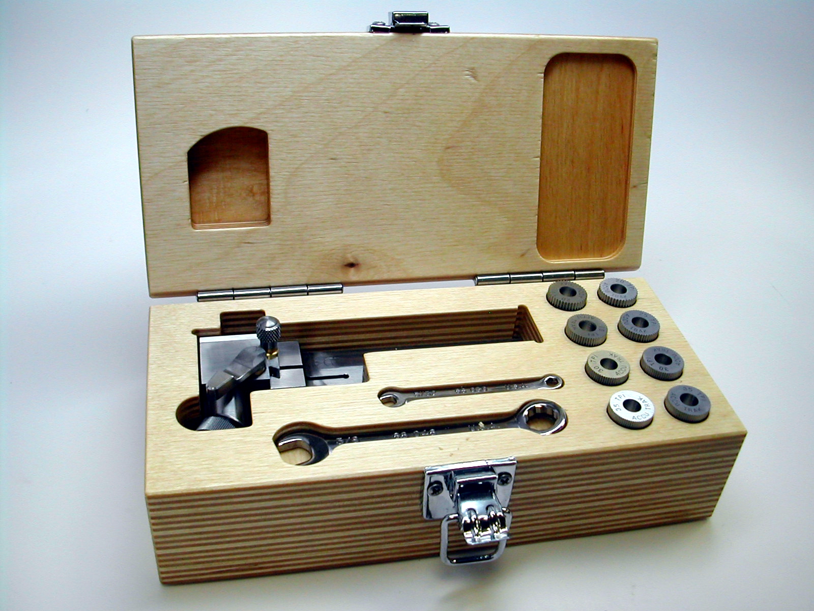
A few shots of the finished cut knurling tool.
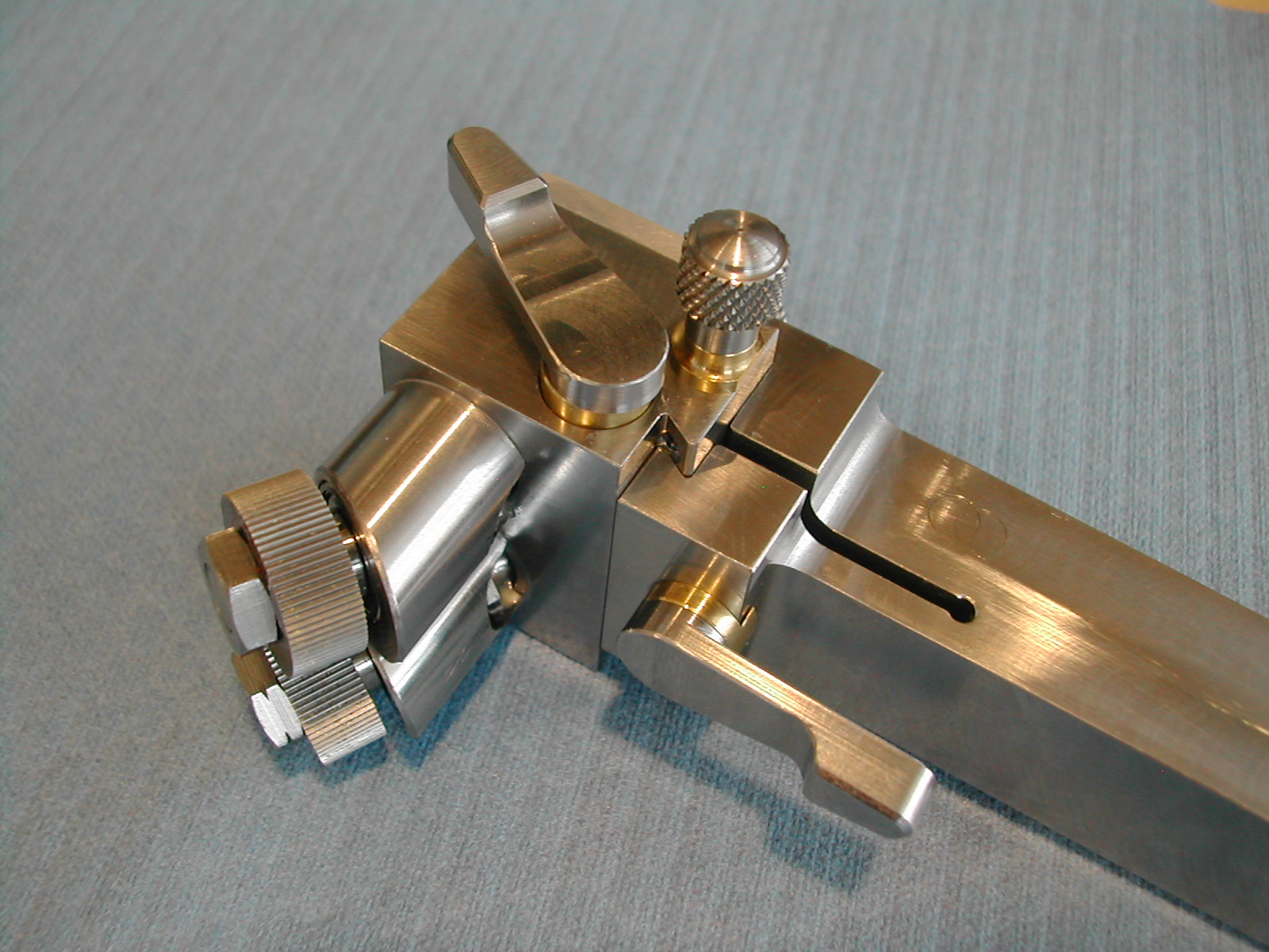
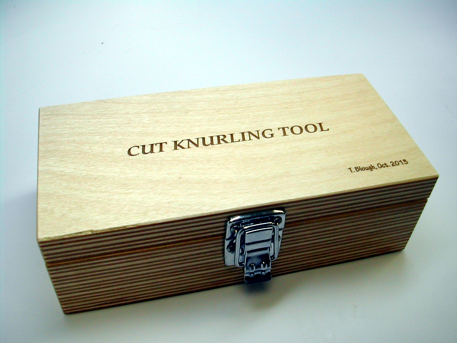
Every good tool deserves a nice fitted wooden case don’t you think?
Disclaimer and License
All material, including the CAD drawings, relating to the construction of the Cut Knurling Tool presented on this site is free to use any way you see fit. However, no guarantees are made regarding the accuracy or correctness of the material presented here.
Downloads
(CAD drawings are in SolidWorks 2013 Format)