
- Bike Light Battery Pack Adapter
- Bike Light Housing
- Bike Light Electronics Package
To finish up I needed hardware and firmware.
The Electronics Package
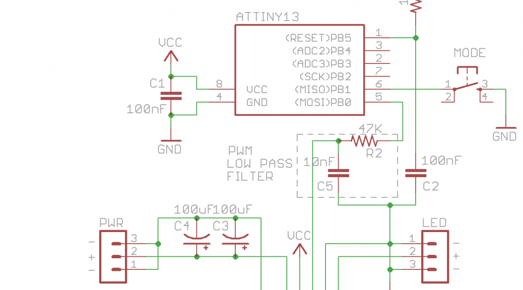
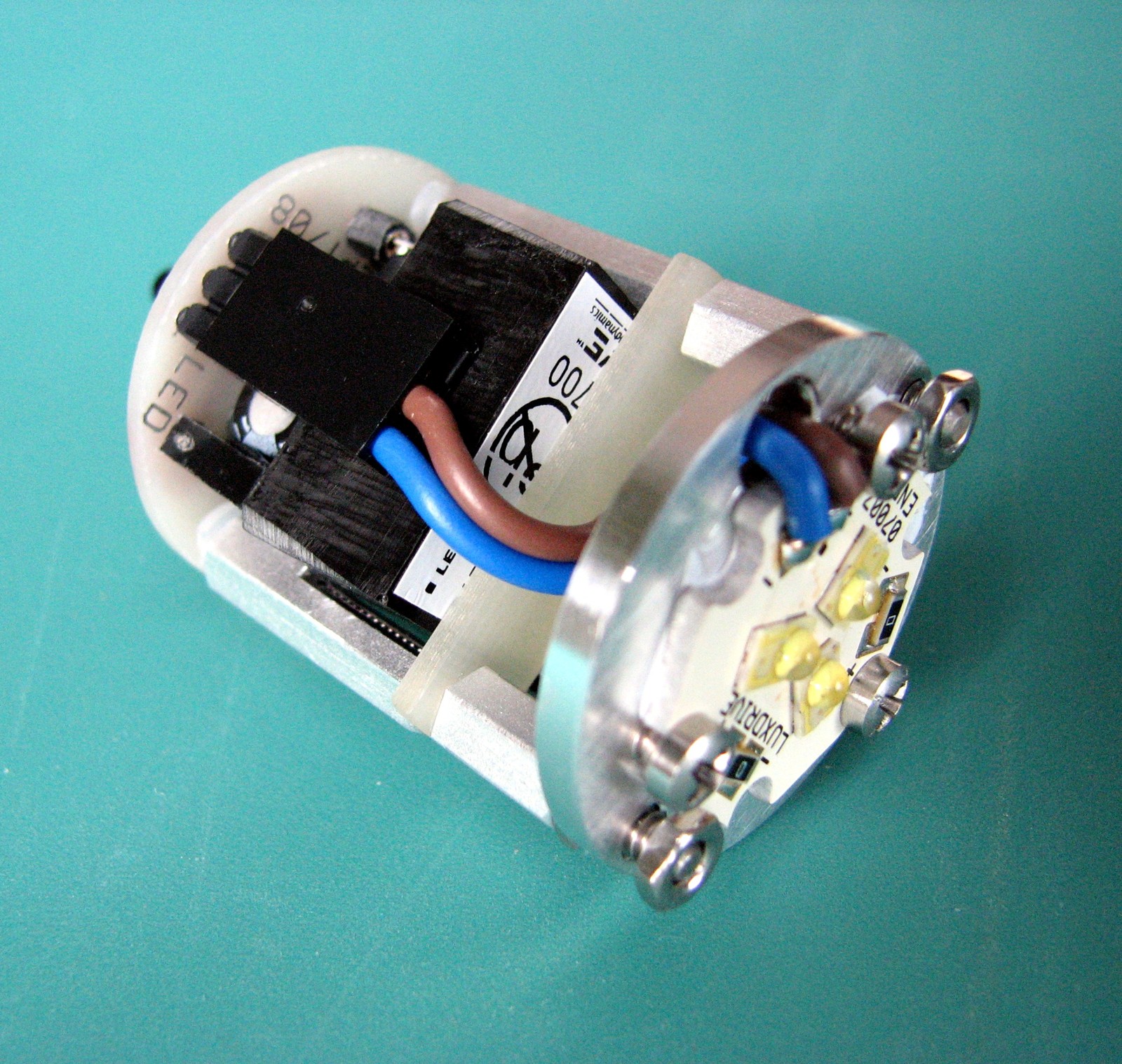
 Compared to the machining, the electronics are a piece of cake. I’m using an Atmel AVR ATTiny13 to control the brightness. +5V Power for the µController is provided by the BuckPuck, the BuckPuck brightness control pin is driven by a PWM signal generated by the µController, and the human interface is a single pushbutton.
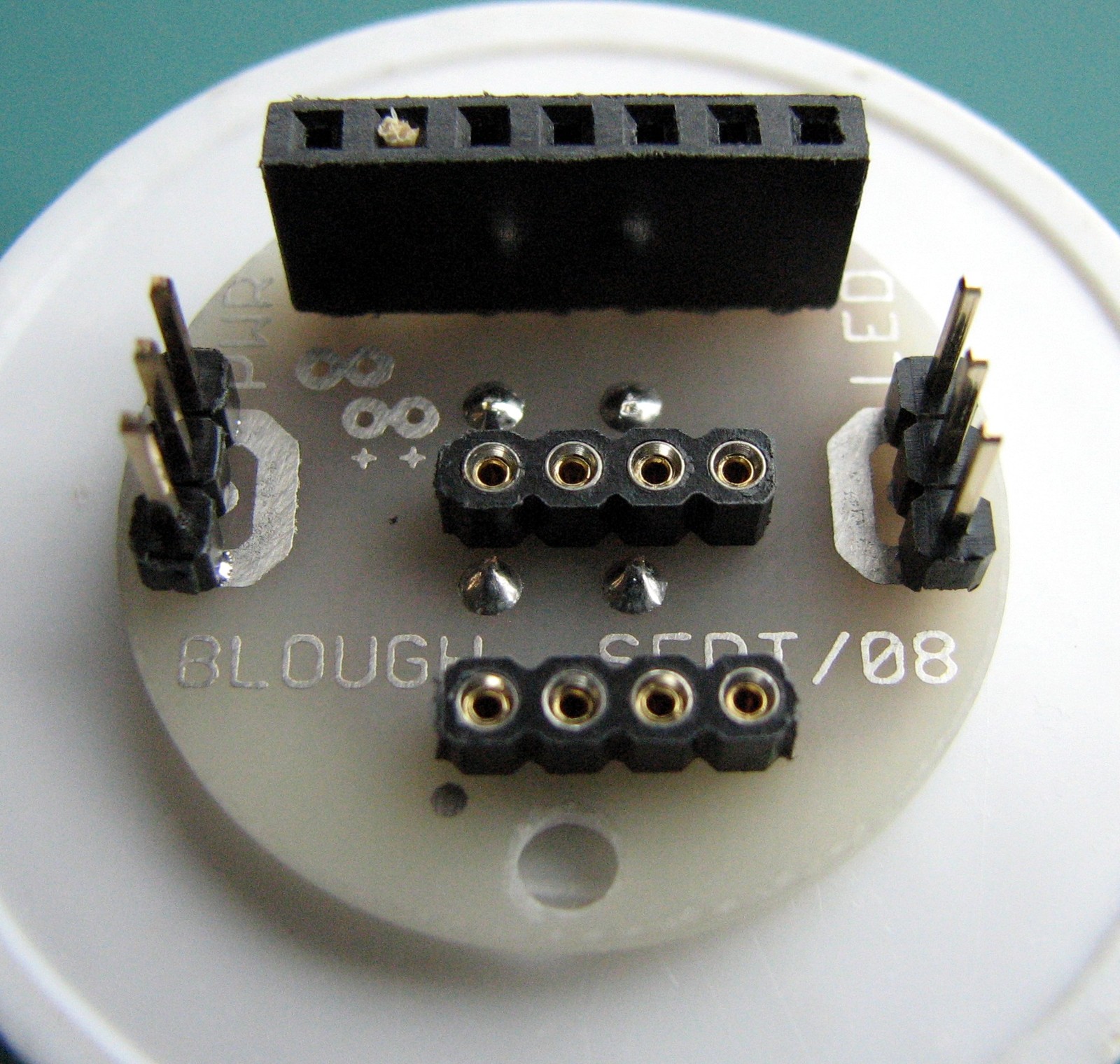
There are three connectors on the board; one for the BuckPuck, one to connect the LED, and one for incoming power from the battery. The battery and LED connections use 3-pin connectors to prevent reversing power and ground. Unfortunately, there is nothing to prevent hooking the connectors up backwards, but they are labeled.
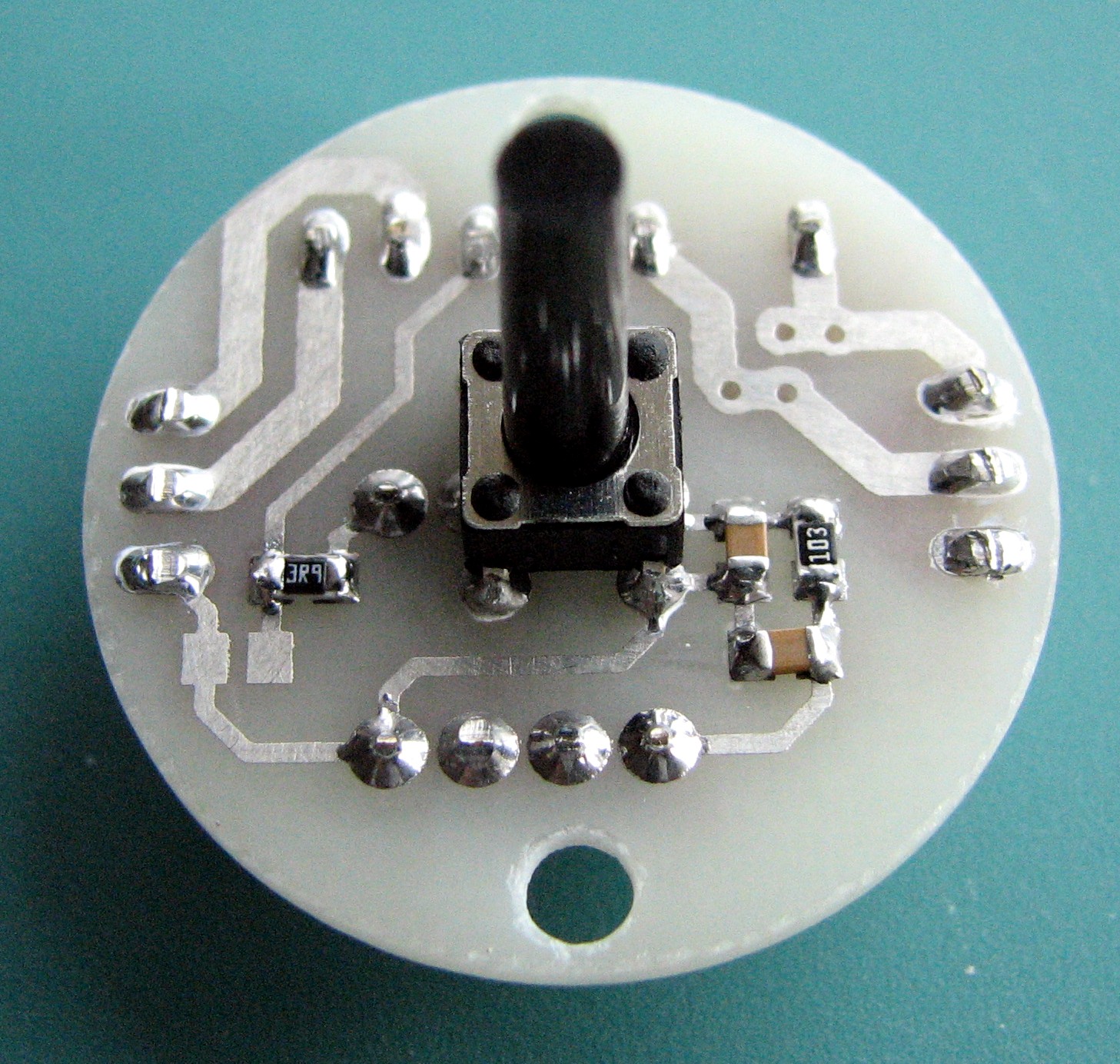
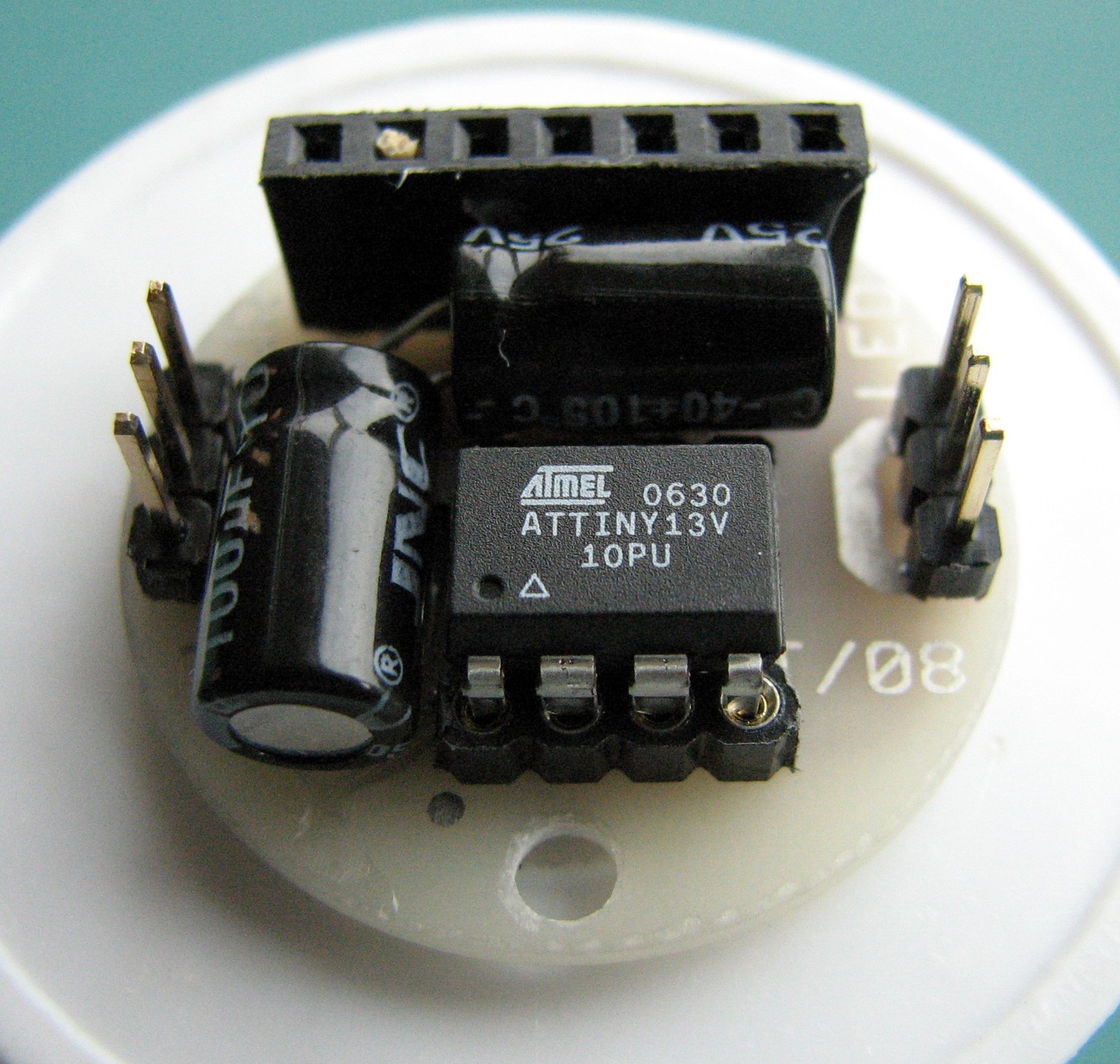
The ATTiy13V is socketed since there was no room on the board for an ISP connection and programming will need to be done off-board. Luxdrive recommends a 200µF filter capacitor. Because of space constraints, this was split into two 100µF capacitors. The switch was trimmed at final assembly to just clear the vinyl cap.
Following are the PCB assembly photos and the electronics package construction:
The Firmware
The 3021 BuckPuck with Control/Dimming capability can adjust the output current to the LED based on a 0-5V control signal. Based on the datasheet, full output current is available when the control signal <= 1.65V +/-5% and output current is 0 when the control signal is >= 4.2V +/-5%. LED current is linear between 1.65V and 4.2V. However, this does not seem to be the case when working with a PWM signal. A 0-5V PWM signal provides full control from 0% to a 100% duty cycle.
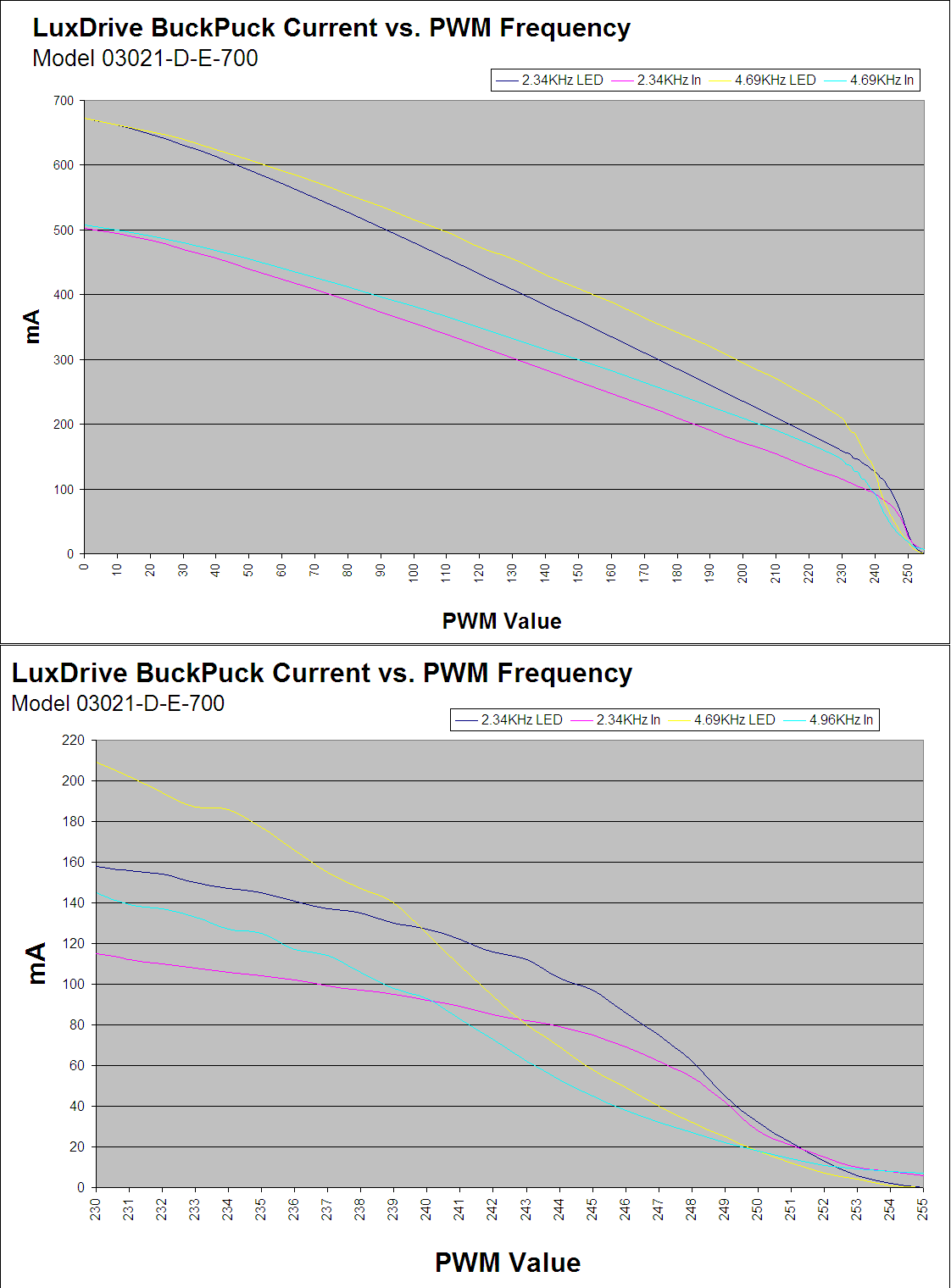 It should be noted that the frequency of the PWM signal does not appear make a difference in the efficiency of the BuckPuck; it does make a difference in the response curves. A higher frequency PWM signal flattens the PWM % vs. Output Current curve at the low current end giving finer control over low light levels. The graphs on the left show the relation of input current to the BuckPuck, output current to the LED, and PWM frequency as a function of the PWM value from 0 to 255 (PWM of 0 is full on, 255 is no light output). You can see the yellow and cyan curves denoting a 4.69KHz PWM frequency flatten out above a PWM value of 234.
These graphs will also let you estimate run times of the light at various light output levels. For my bike light, I chose to have three levels available. A high output useful for blinding anyone in the vicinity resulted in a current draw from the battery of 508mA giving right at 3 hours of light at this level. My medium level, which I use most of the time, draws 228mA resulting in 6 hours of battery life, and when in town, I use the low output which is still much brighter than my wife’s CatEye EL320 which has a claimed 1000 plus candlepower. This gives me over 45 hours of runtime.
A final note about output levels has to do with the “off” setting. Turning the light off does not really turn the device itself off. The BuckPuck and the µController are still running and consuming around 7mA of current. Don’t worry, if you forget to unplug the light’s power cord from the battery at the end of your ride, it will still stay powered up for another 9 days or so.
A single pushbutton is used to control a software implemented state machine. Currently there are three steady brightness levels and two pulsed brightness levels. The pulsed modes are used to increase other’s awareness of the rider without periodically completely extinguishing illumination as some flashing bike lights do. It is hoped that this will still increase the riders visibility to others without the rider having to deal with his path going dark ever second or so.
The BikeLight remembers the last used mode before power off and returns to that mode after the first button press to power it back on. A shortcut mode enables one to quickly go to steady full-on mode at any time without cycling through the remaining modes.
The shortcut mode toggles between steady full on and the previously selected mode. To enter the shortcut mode, the pushbutton is held for 1-second. A 1-second press turns on steady full on mode, and the next 1-second press reverts to the previous mode.
To turn off the LED, press and hold the button for 2-seconds. The BikeLight is in standby mode in this state and will continue to draw approximately 7ma To completely power down the BikeLight, disconnect the battery. To turn the light back on, or to change between output modes, a quick press is all it takes.
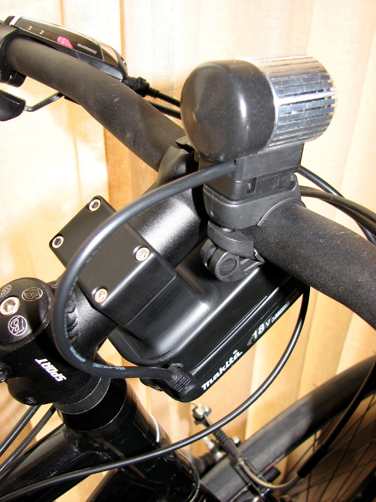
The Finished Product
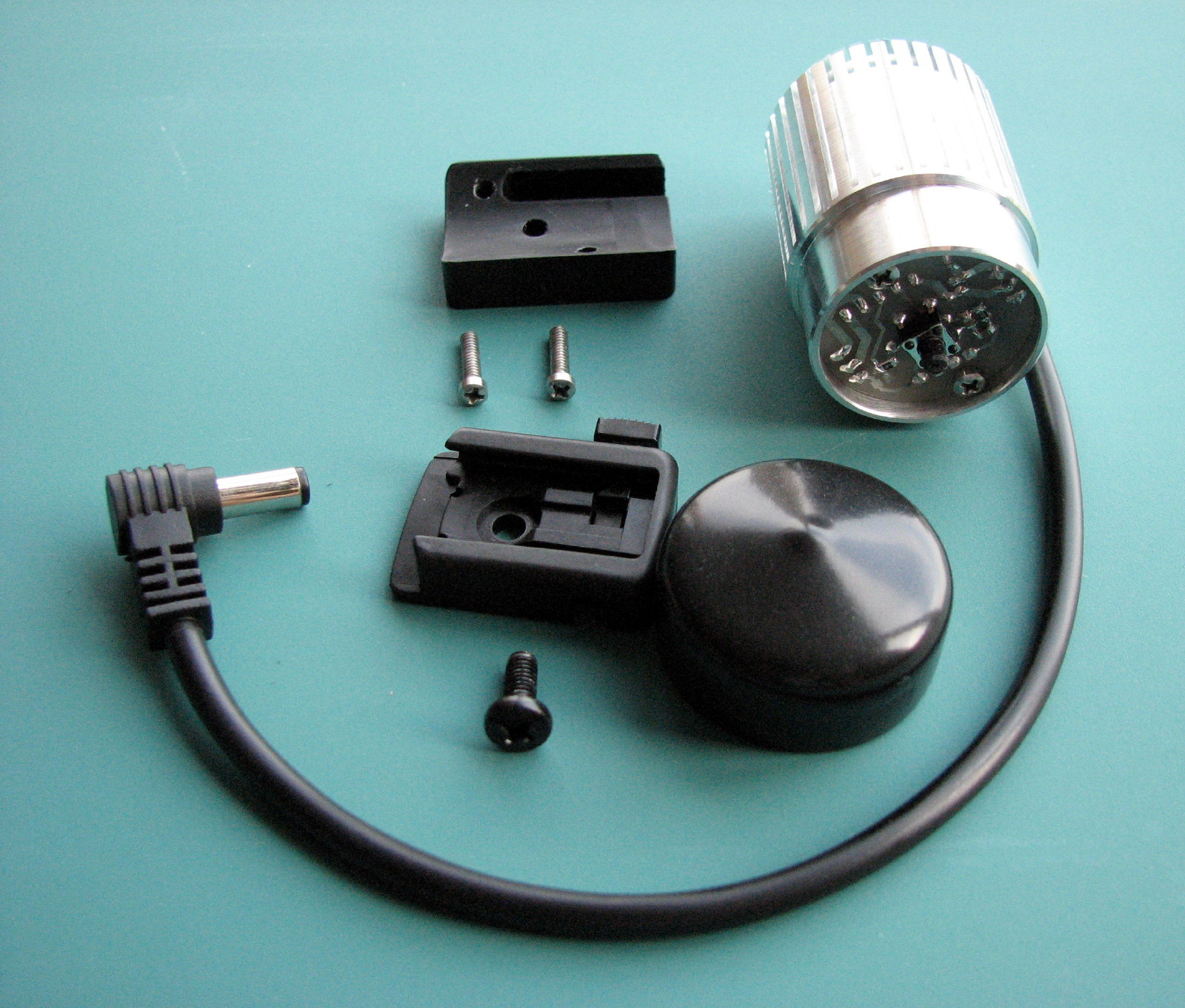
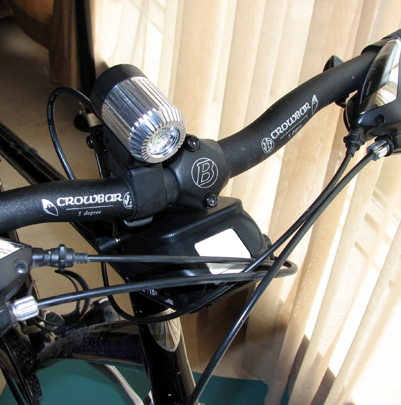
And we’ll end with a few photos of the final assembly and the finished bike light:


A Little Anecdote about Chinese Quality
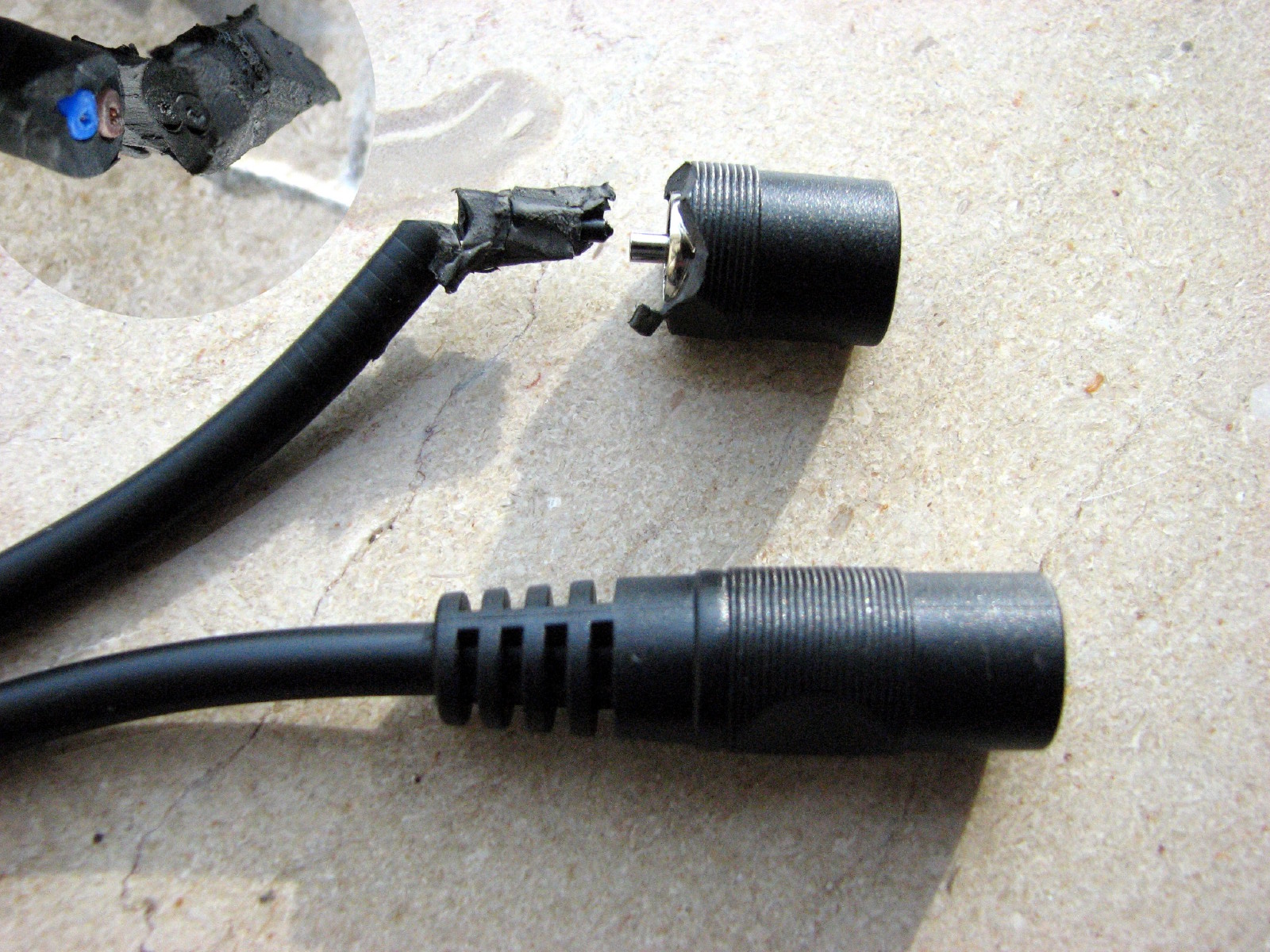 Take a close look at this photo. I bought a handful of the power cord extensions at a local electronics market in Suzhou, China where I live. I put these on my first bike light I made and spent a good couple of hours scratching my head why the damned thing wouldn’t work. I finally narrowed it down to where it couldn’t be anything else, so out came the X-Acto knife and I dug out the truth.
In the closeup, you can actually see where the over-mold plastic flowed around the cut ends of the wires and into the receptacle’s center conductor where one of the wires should have been soldered. The whole batch was this way. Like a lot of things in China, it just needs to look OK to make a sale, it doesn’t really have to work!
Disclaimer and License
It worked for me so it should work for you, but no guarantees. Feel free to use the schematics, drawings, and information on this page as you see fit, but a little attribution would be appreciated.
Project Sources
- AVR Studio GCC Source (14K .zip)
- Cadsoft Eagle Files (65K .zip)
- AutoCad 2008 Model (3.8M .zip)