
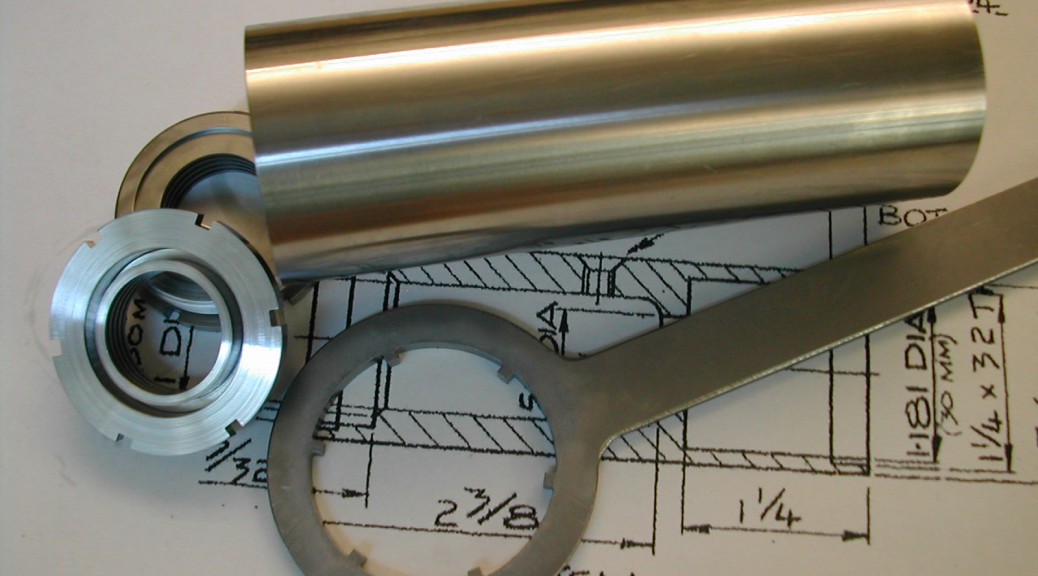
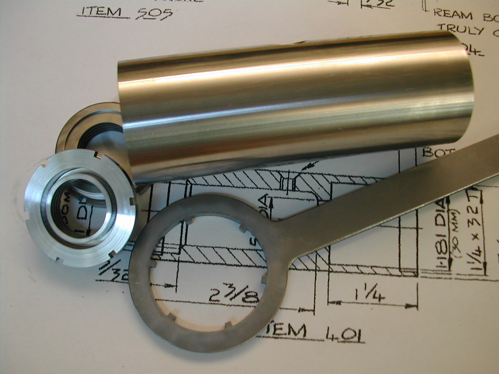
- Quorn Parts 401/404, The Quill Body & Caps
- Quorn Part 407, The Spring Box
In the end, I decided I’ll build the spindle per Chaddock’s plans and maybe build a larger spindle later. I haven’t decided yet how I’m going to handle the wheelhead casting – bore it for the 1.375″ quill and re-work it later if I decide on the larger quill, or open it up to 1.5″ and plan on sleeving the Chaddock quill to fit. For now, I’m just going to worry about building the quill.
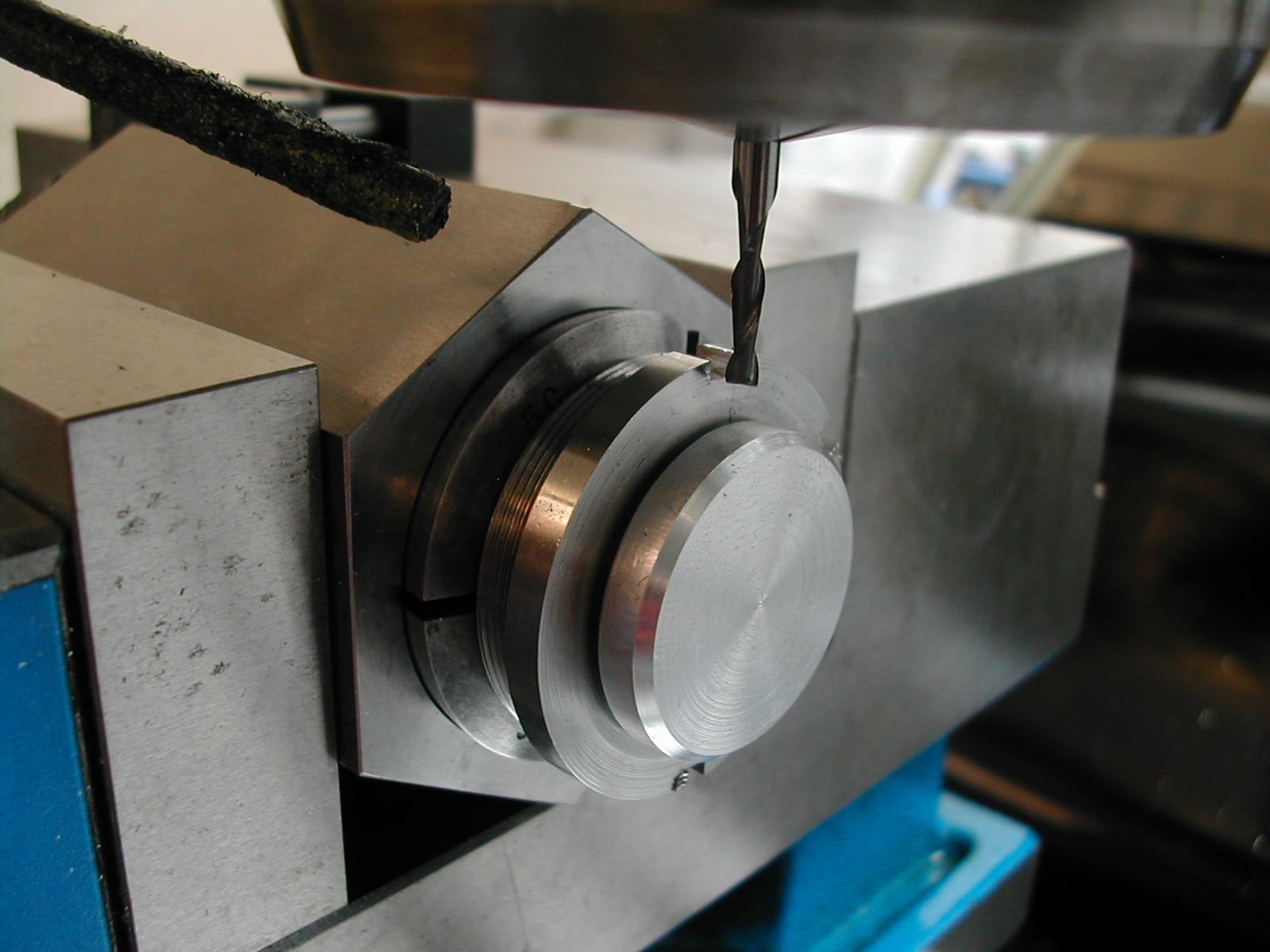
After indicating, the blank was drilled ∅5/8″ approximately 1/2″ deep.
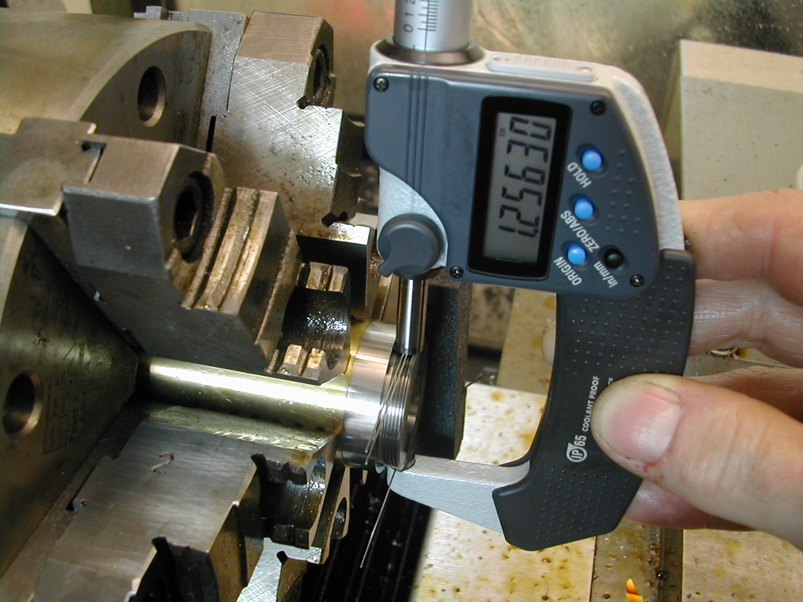
The face was cleaned up, and the thread boss was turned to ∅1.247″ and the thread relief cut. The 32 TPI thread was then cut. Maximum pitch diameter should be D – 0.64951905*P = 1.25 -0.64951905/32 = 1.2297 so measuring over ∅0.018″ wires, I was shooting for a measurement of PD – 0.86603P +3W = 1.2297 – 0.86603/32 + 3*0.018 = 1.2566″.
With the outside completed, a 0.031″ grooving tool was used to bore the cap ID, cut the internal labyrinth grooves, and add the inner bearing race relief.
The end cap was then parted off 0.02″ long. I usually part almost all the way through and then finish with a hack saw. This keeps the part from falling into the chip tray, and keeps the bit from snagging as it breaks through. I repeated this process for the second end cap.
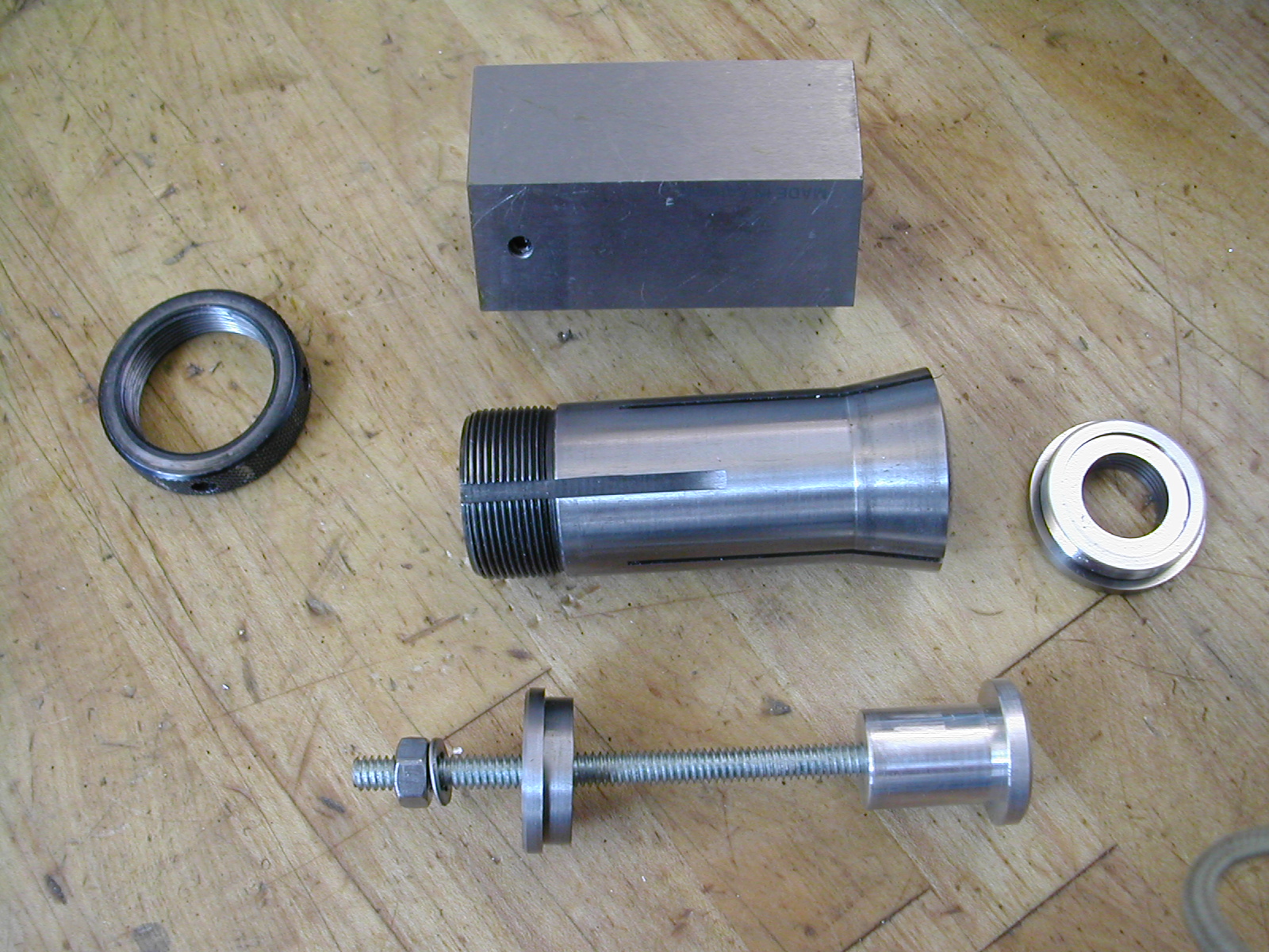
I plan on using the quill body as a machining fixture to finish the end caps. Before I can do that, I need to go ahead and cut the spanner grooves on the end caps so I can tighten and loosen them on the body. I made a simple arbor to center the end cap and pull it tight against an 11/16″ collet in a hex collet block.
The collet block and end cap was then set-up in the mill and the six spanner slots were cut. This was repeated for the second end cap.
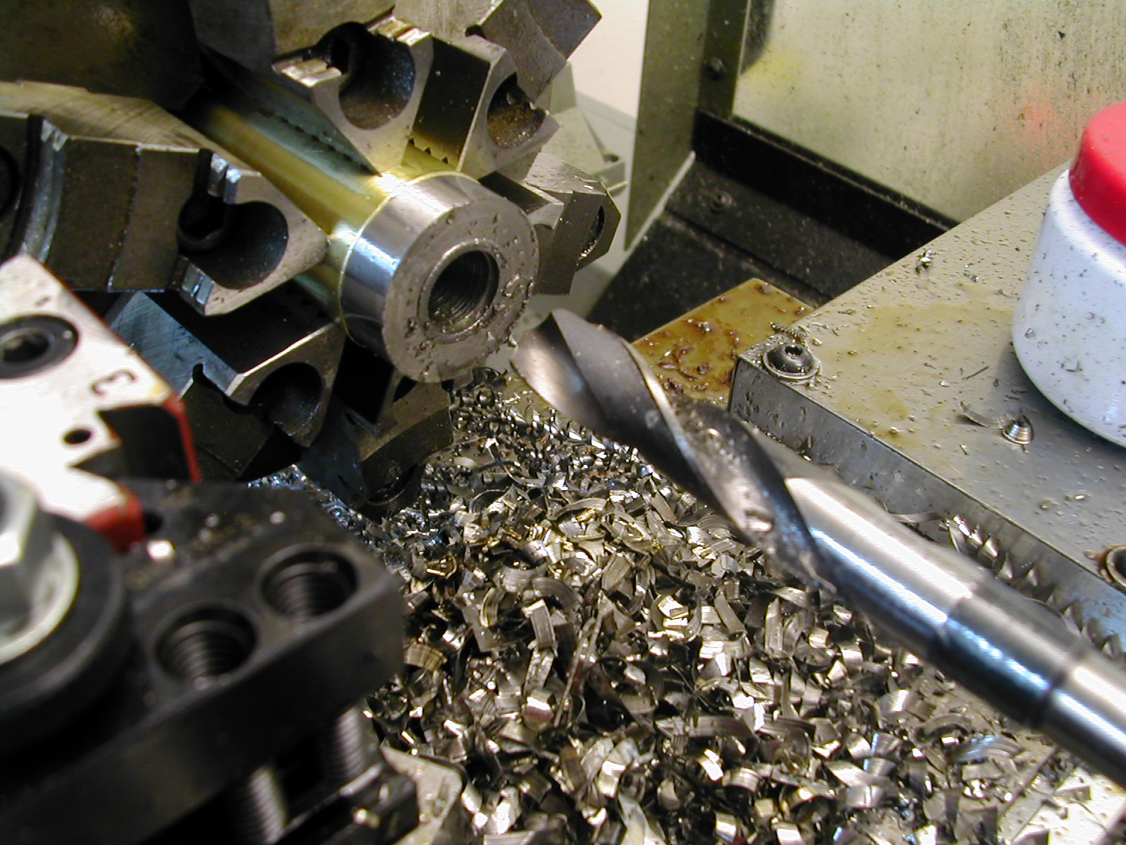
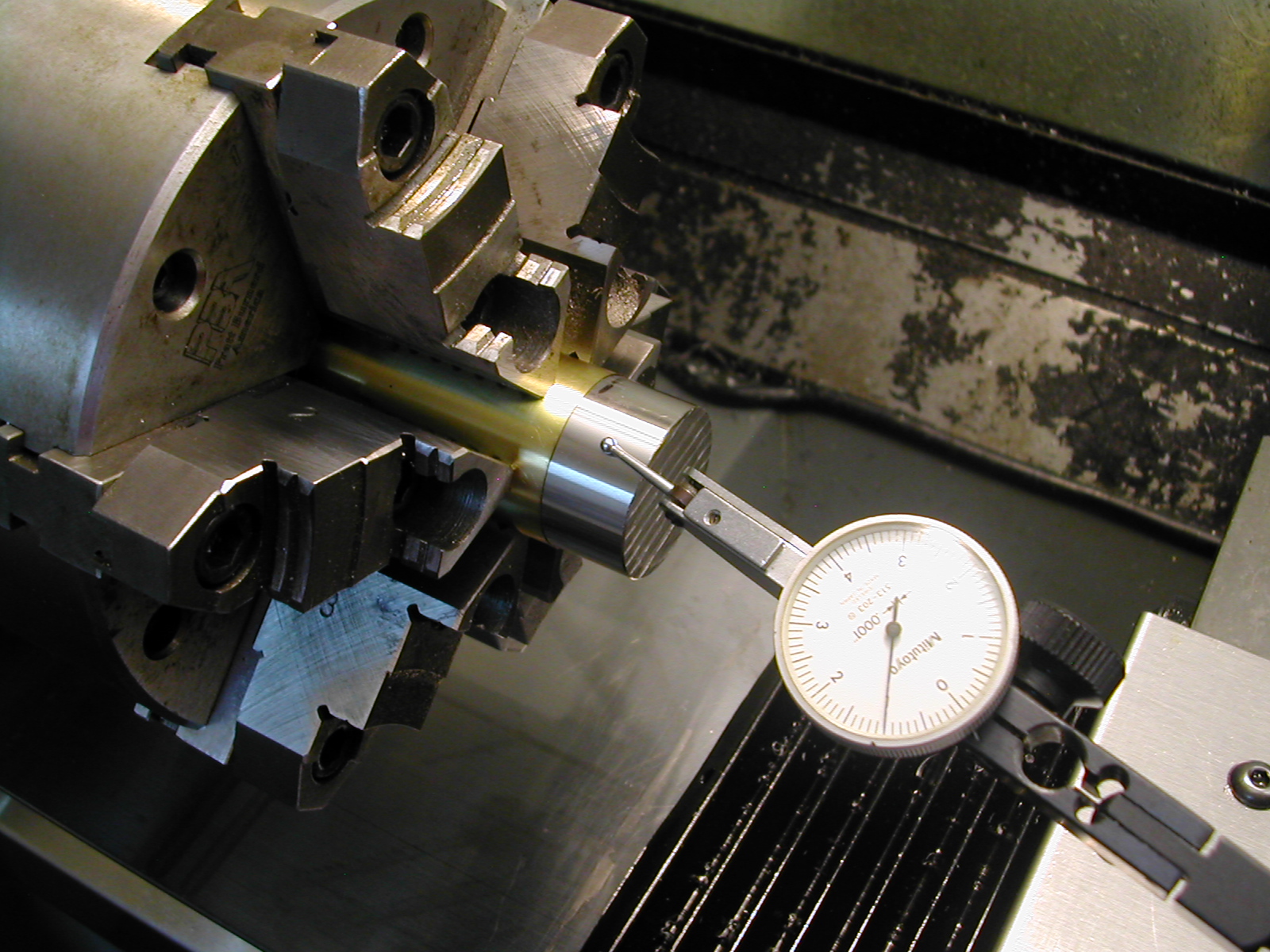
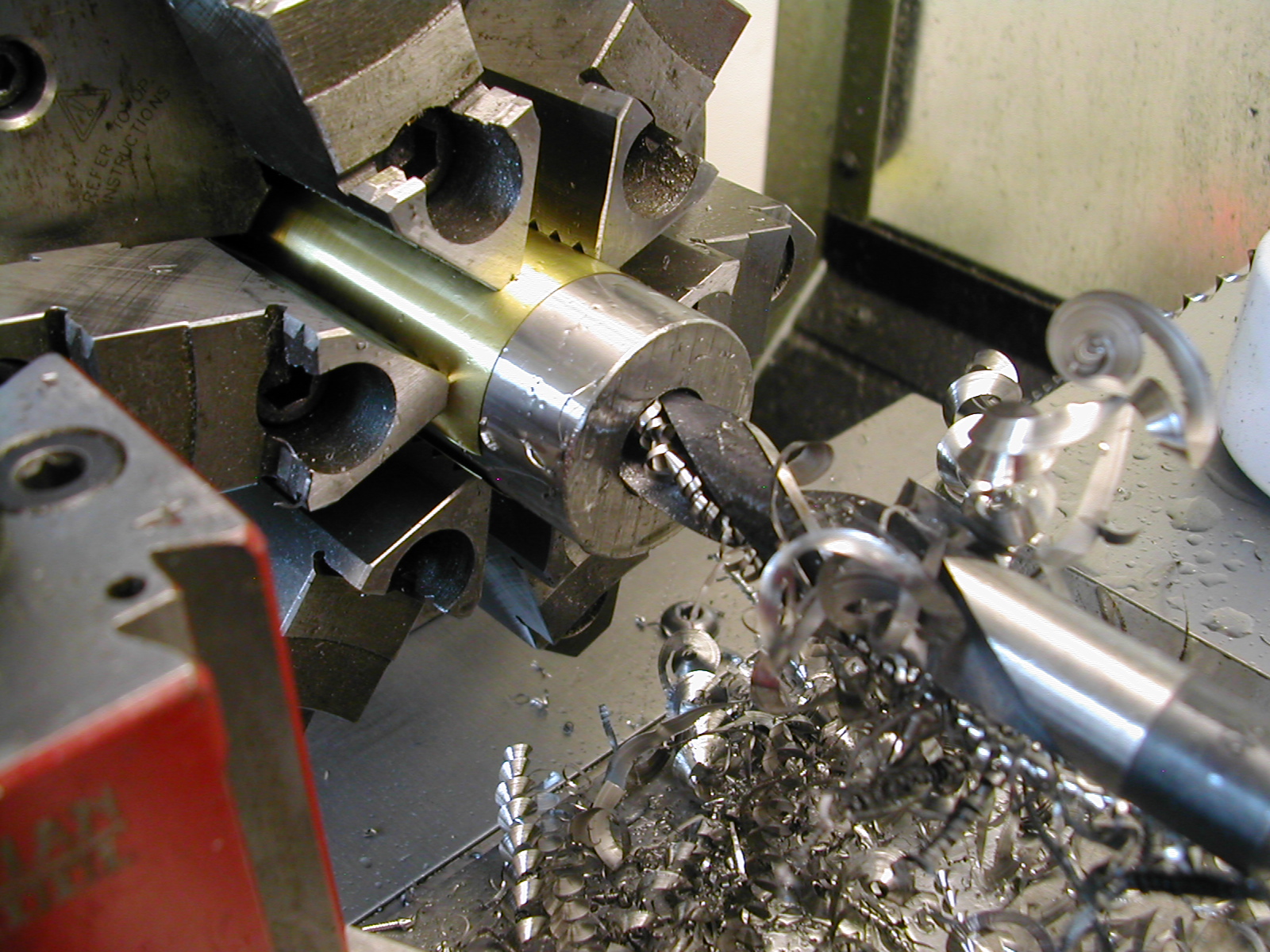
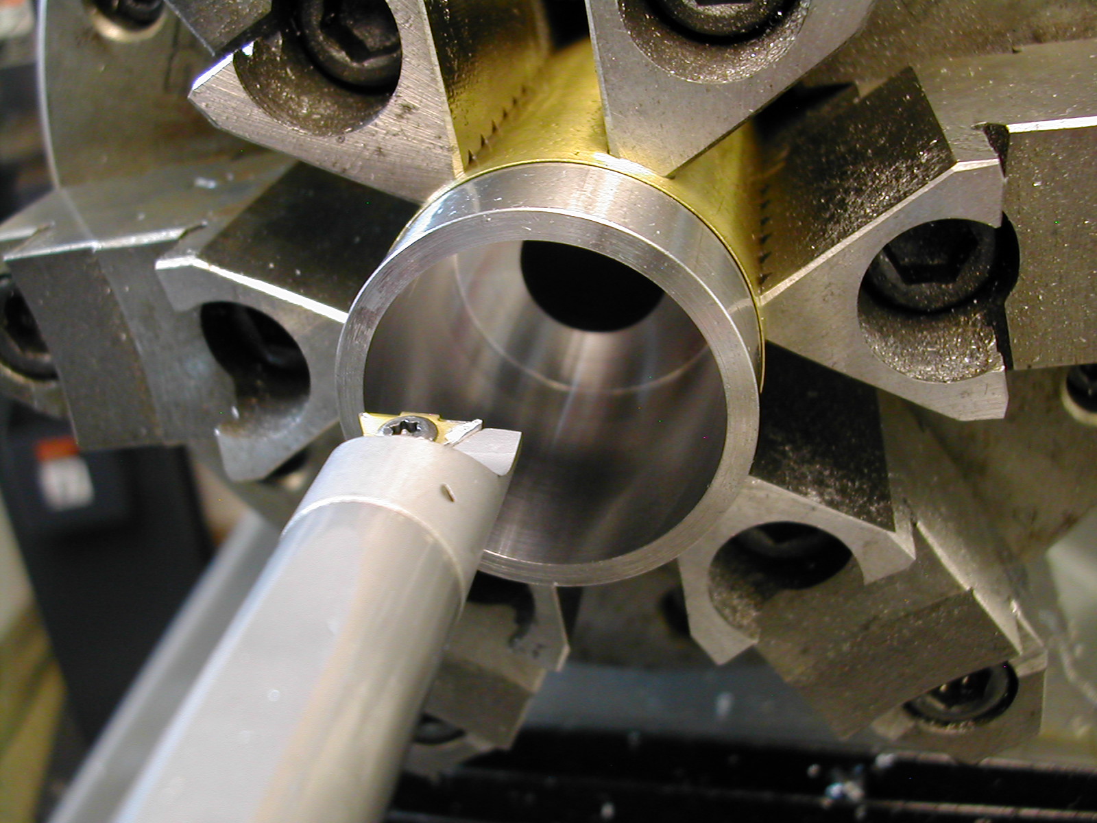
With the end caps prepped and ready, I moved back to the lathe and indicated the now shorter body blank back in true. I pre-drilled 3/8″ and followed with a 39/64″ drill through.
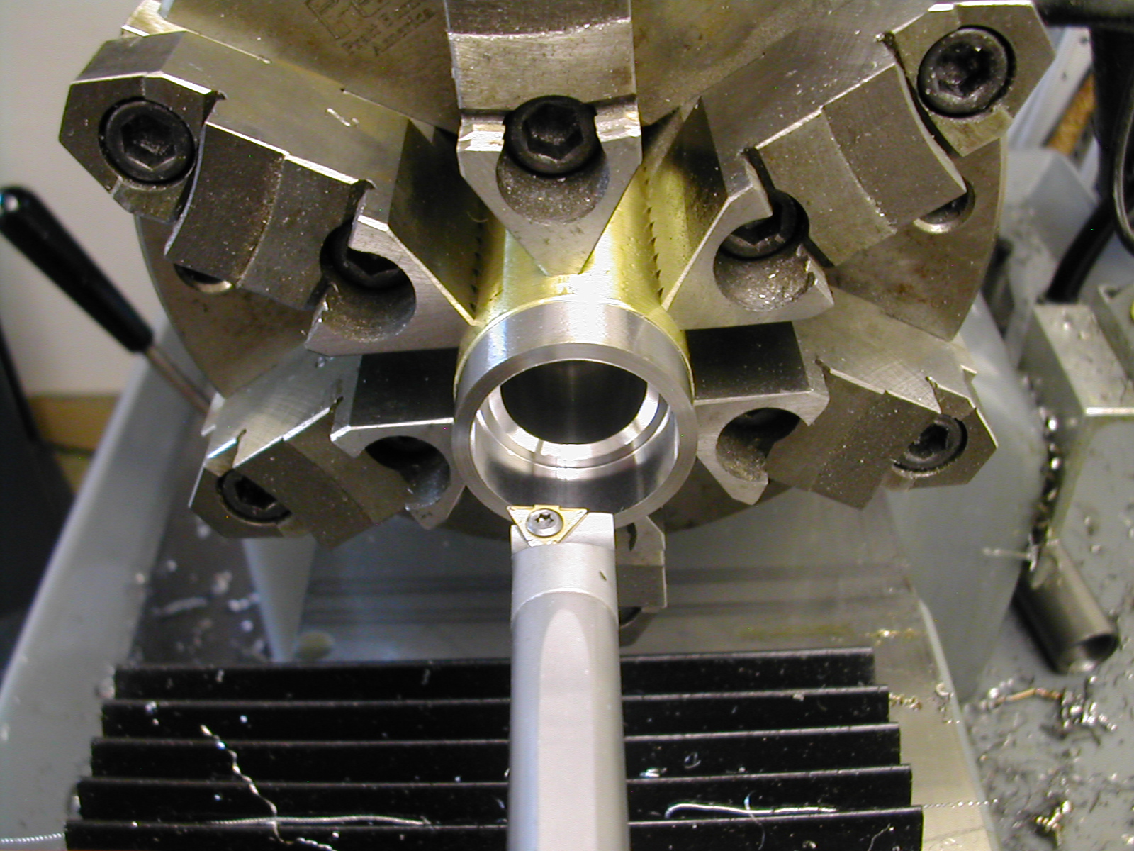
I used a 1/2″ boring bar to face the end of the part and establish my dataum. I then proceeded to finish the ∅5/8″ and ∅7/8″ features including the radius and chamfer. At this point, I left the bearing race and thread area undersize at ∅1.160″ with 0.005″ left to take off the shoulder as well.
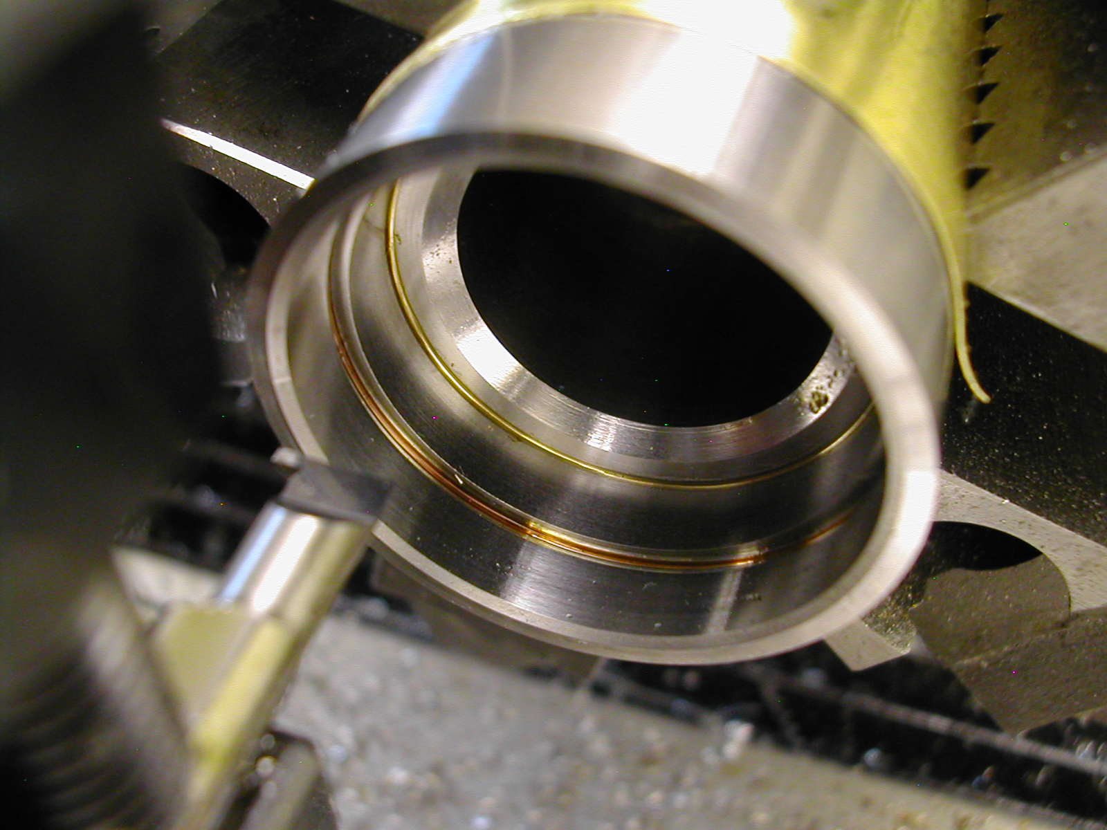
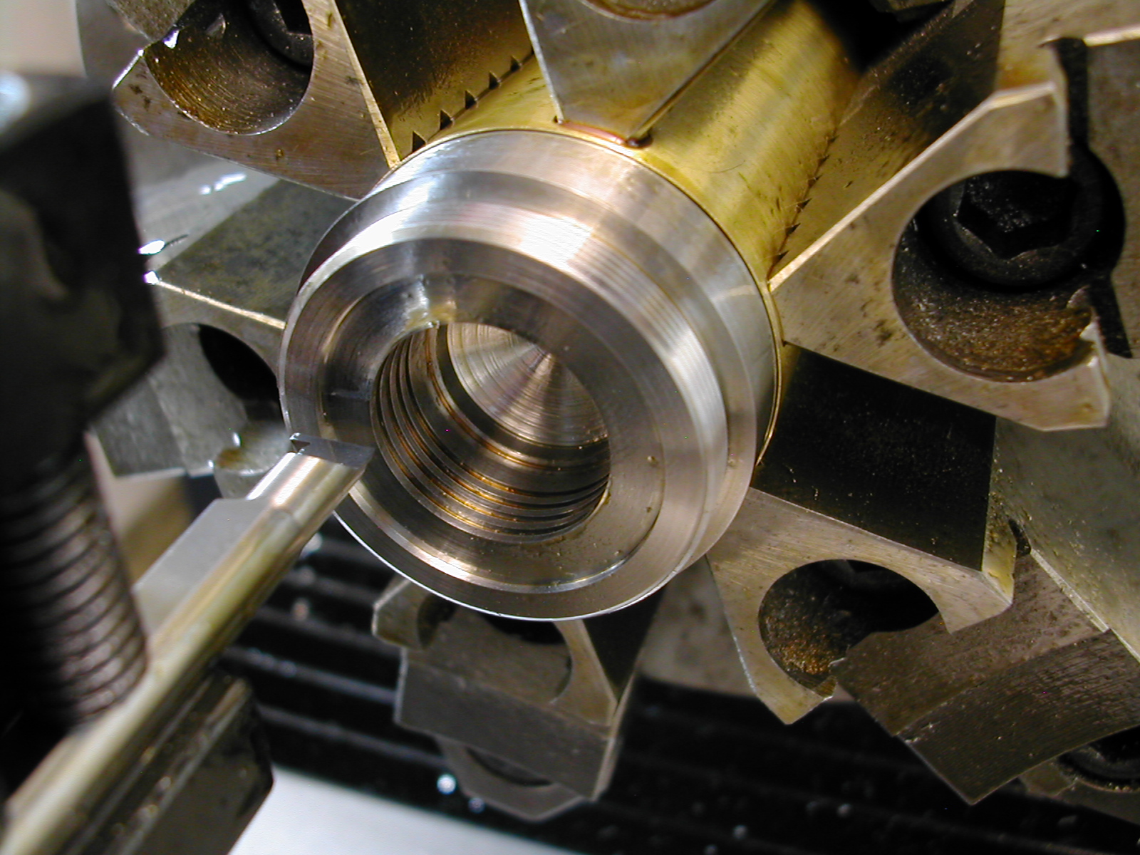
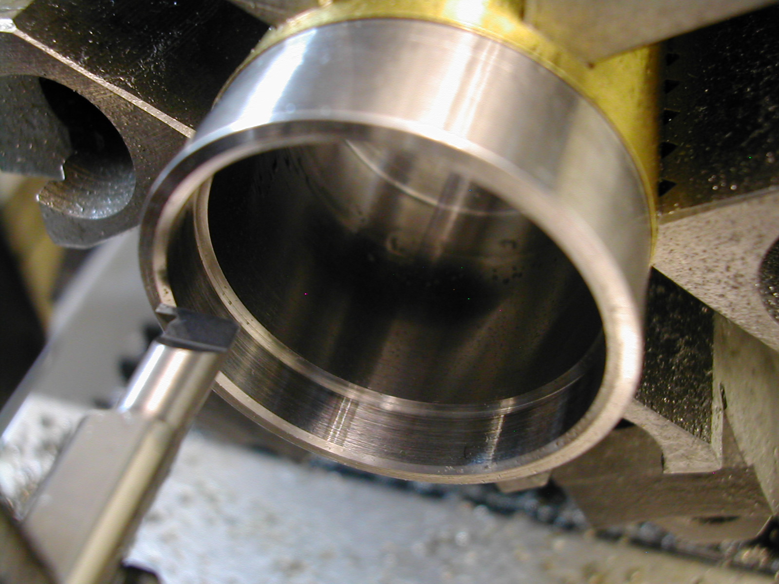
Next, I used my 1/32″ grooving tool to bore the ∅30mm bearing seat to an easy push- fit on the actual race and take the finish cut on the back face. With the bearing bore established, I then used the grooving tool to bore the ∅1.206″ minor thread diameter and add the thread relief groove.
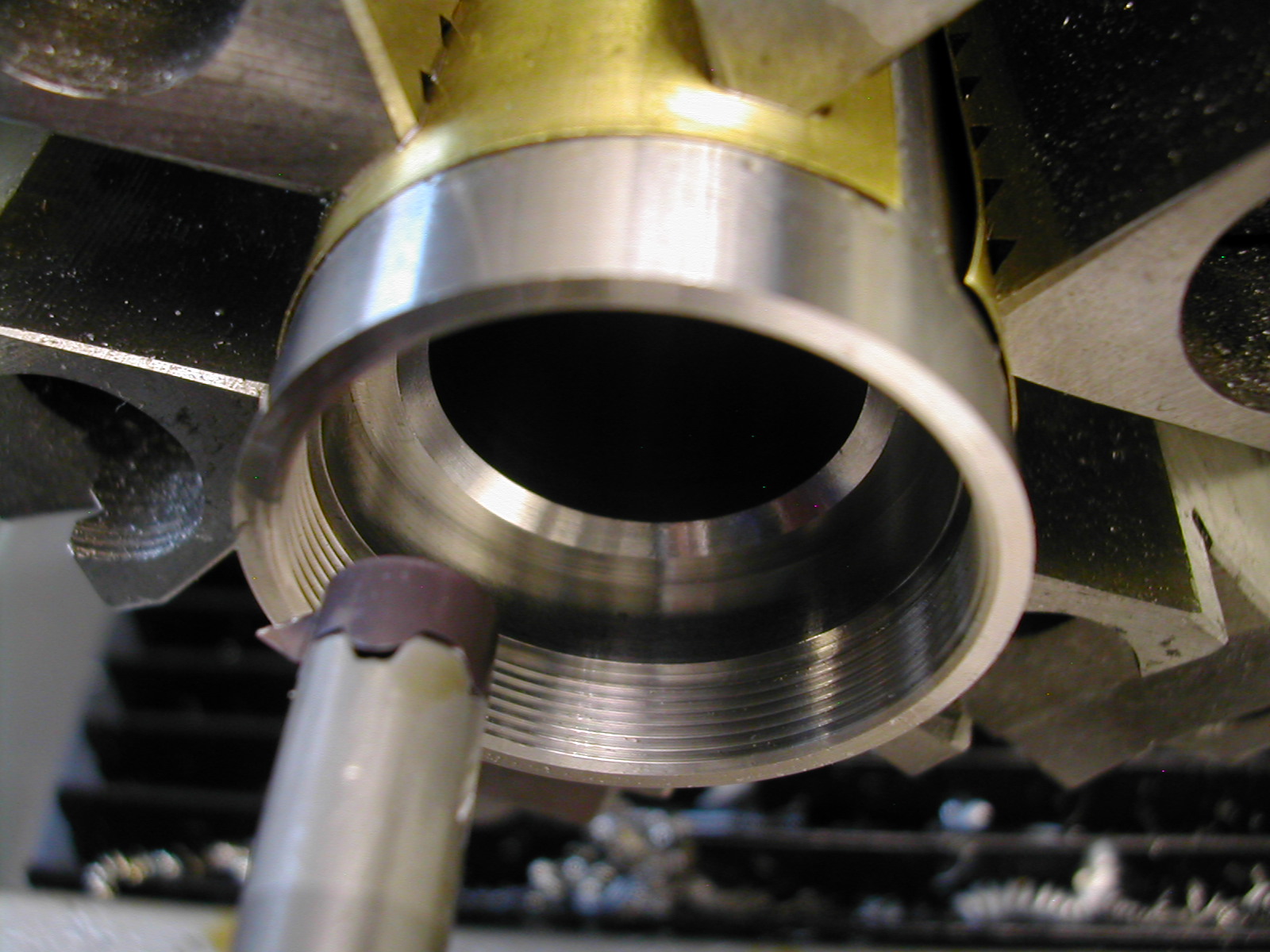
Threading the ID was a tedious process as there is very little support under the sharp-V insert tip and therefore they break very easily. To account for this, I took 0.002″ off the diameter at each pass and snuck up on the finish size at 0.001″ off the diameter for the finish passes. With the end cap threaded on, I ended up with no discernible radial movement of the end cap and only 0.0007″ of axial end-play on the threads.
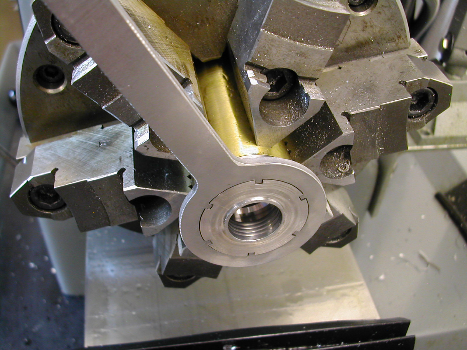
With the threads completed on this first end, I could then use this as a fixture to finish the end caps. The end cap was fitted and tightened down. Since I still had my zero from facing the body, It was easy to back off 7/64″ and take the facing cut on the end cap.
Now that the end cap was faced to length, I could trepan the labyrinth groove. These last two steps were repeated for the second end cap.
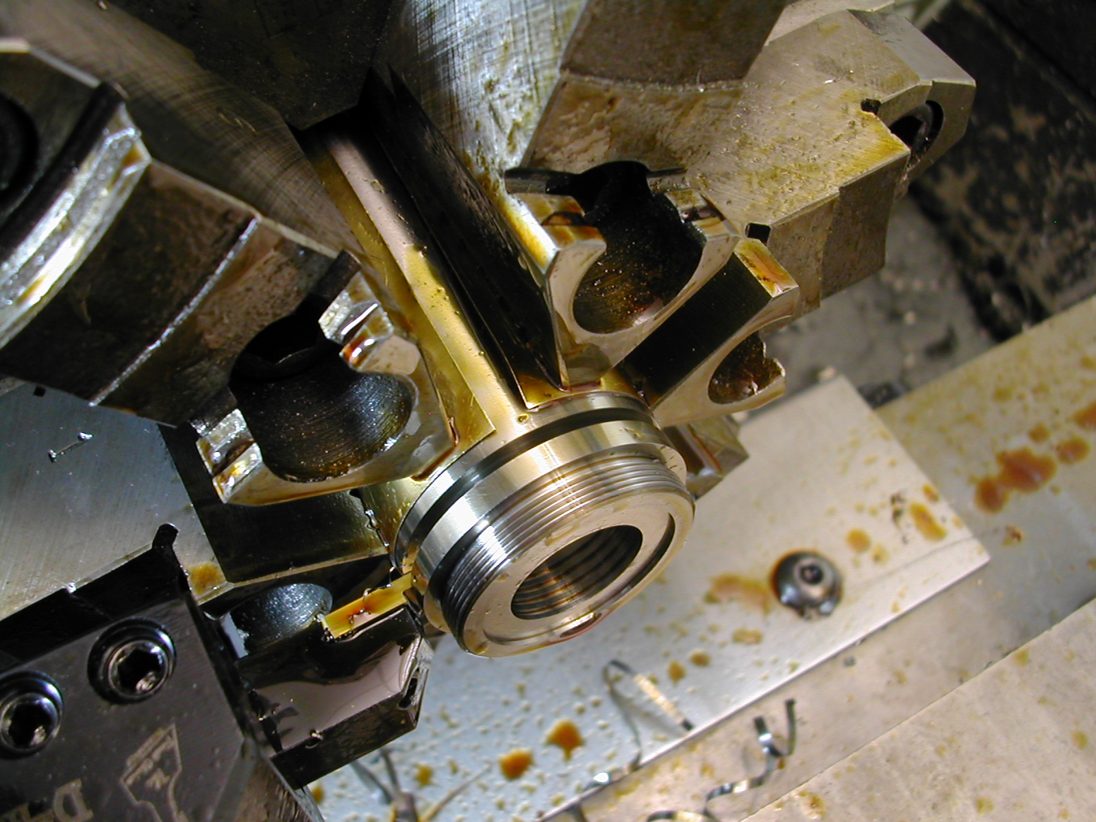
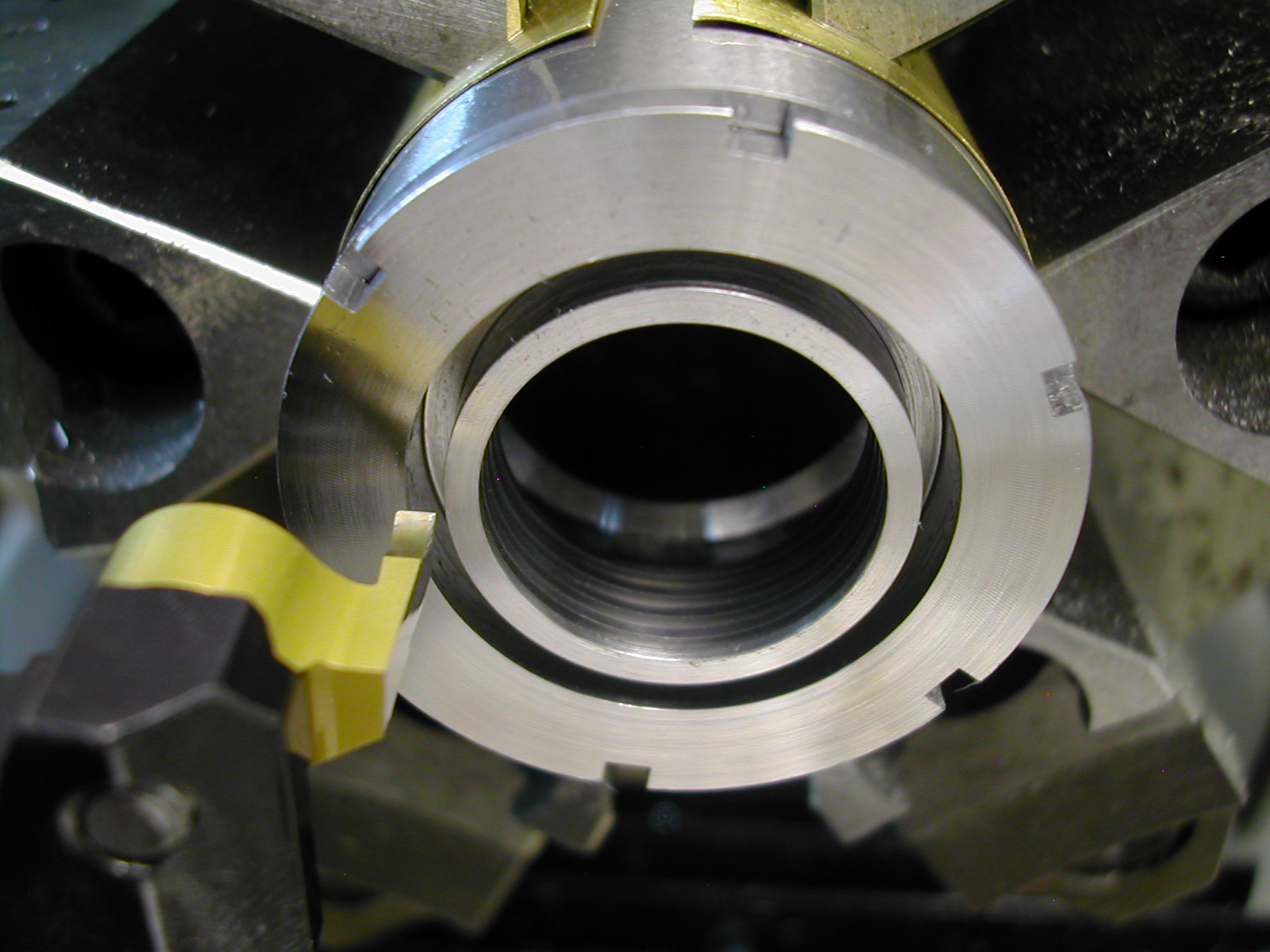
To finish the quill body, the part was rotated and re-indicated in the lathe. I again used my 1/2″ boring bar to cut the ∅30mm feature for the spring box and bearing seat. This was a close slip-fit on the bearing race.
The 1/32″ grooving tool was back to establish the 1.206″ minor diameter and cut the thread relief for the 1.25″-32 thread.
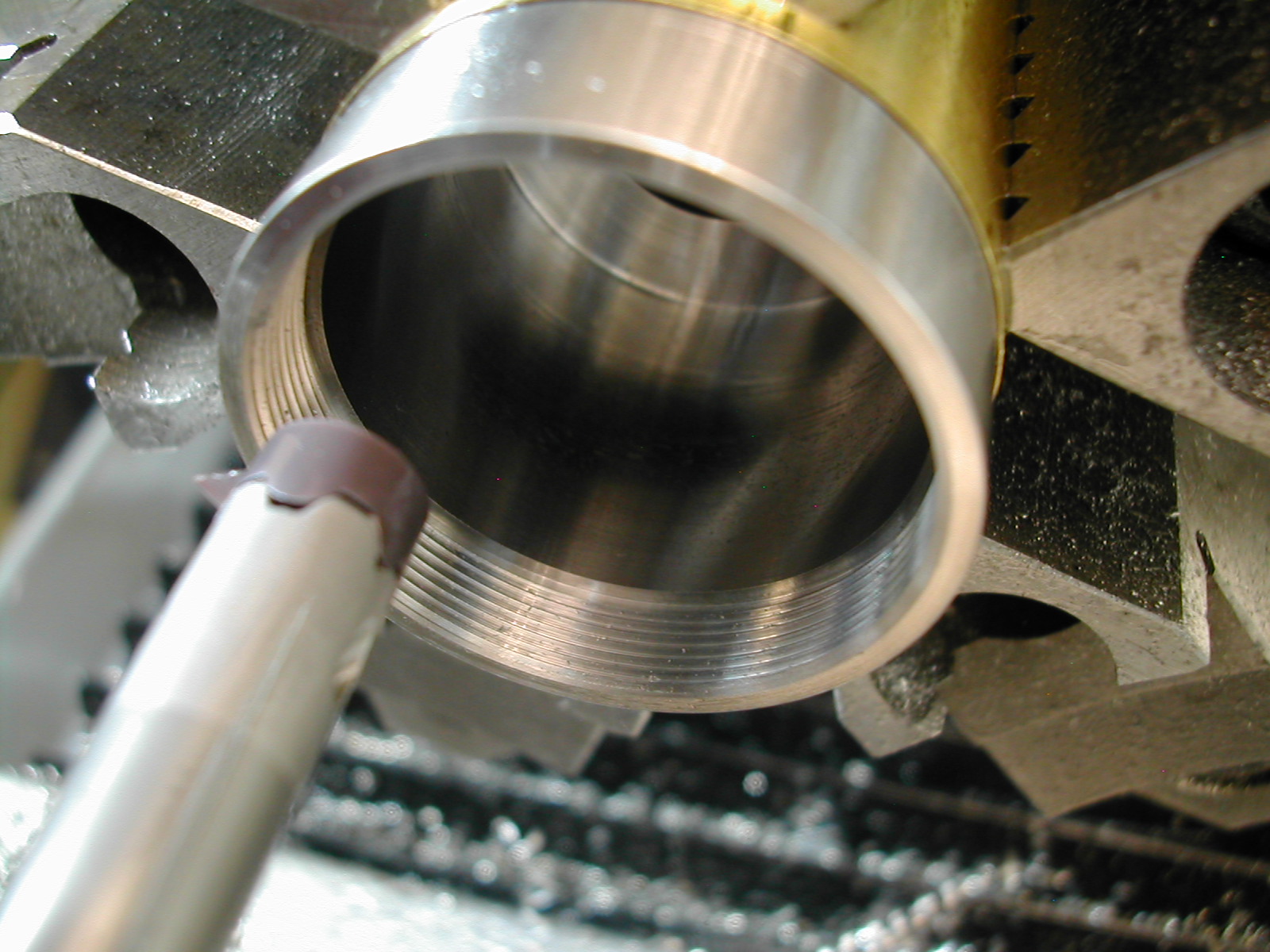
This was followed by the same tedious threading operation as before.
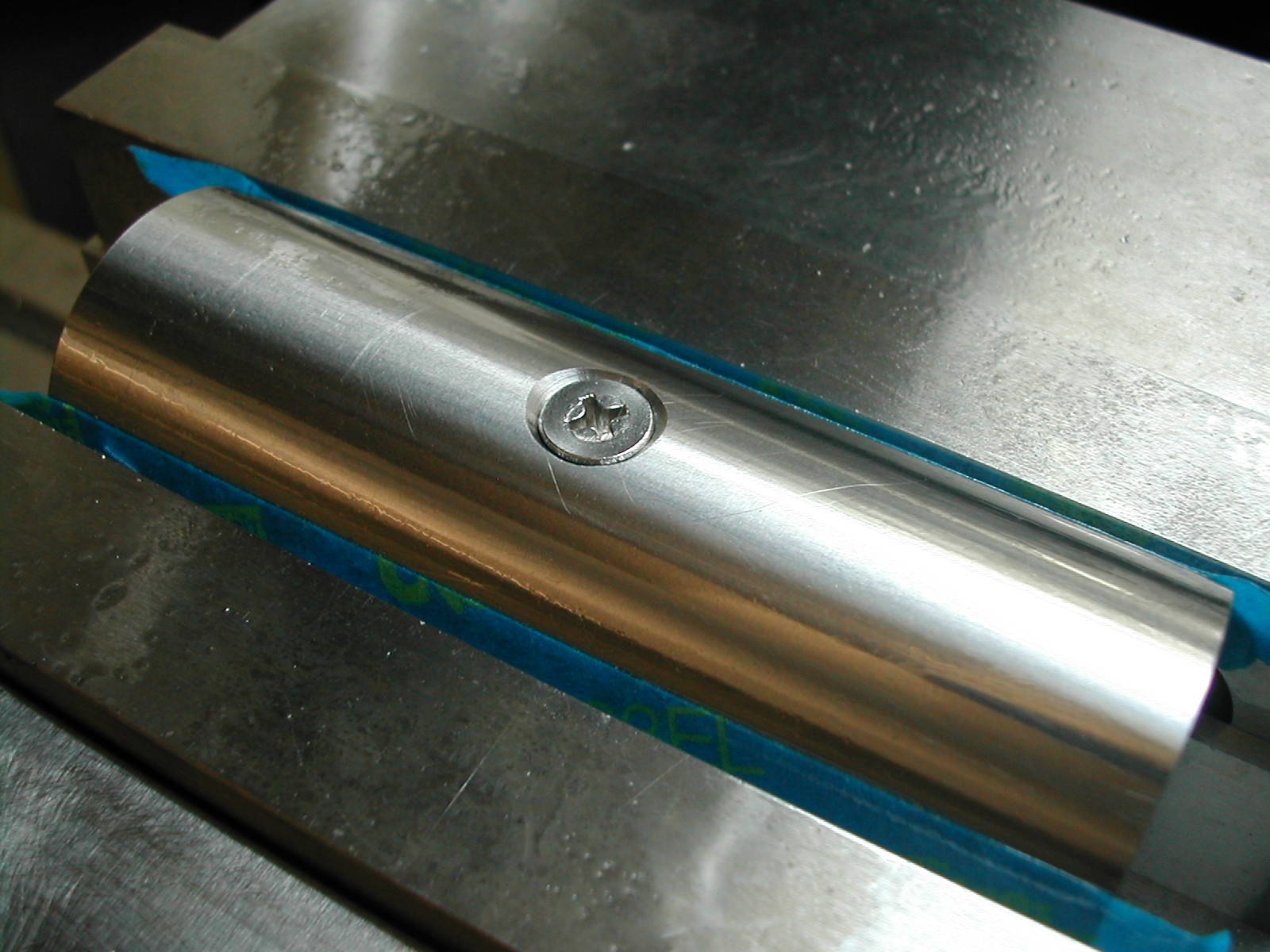
The last operation on the Quill Body was to add the oiling hole. The screw I used had an undercut head which was great as it allowed me to add a 4mm x 6mm O-ring to seal the screw.