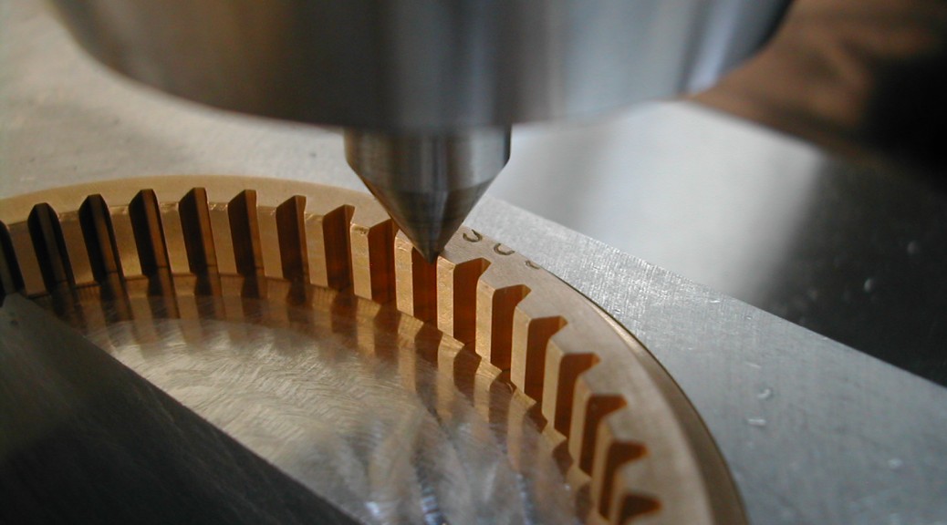
- Hodgson Part 018, Cam Ring
- Hodgson Part 019, Cam Gear & Assembly
I turned a stub arbor with a 1/4″ thick aluminum washer to mount the brass gear for machining. You want a good tight fit on the ID of the gear.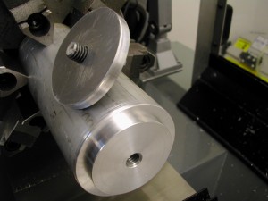
 Here is the stock gear mounted on the arbor ready for machining. The aluminum washer is 2.25″ in diameter.
 I’ve turned both the OD and the step and now I’m breaking the edges. I’ll put a slightly larger break on the backside to make sure and clear any corner radius on the cam ring where this seats. Make sure the OD will be a slight press-fit to a tight slip-fit in your cam ring.
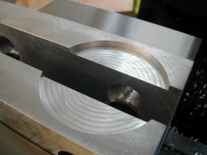 Moving over to the mill, I’ve cut a circular pocket in a set of aluminum soft jaws. I clamped on a 3/4″ wide parallel while cutting the pocket to 2.502″ diameter. Make sure and set your zeros or record your center position for the pocket.
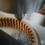 At this point, I’ve got the cam gear sitting in the recess in the jaws and the jaws closed down to where the cam gear can just rotate. With X still centered, I’ve chucked up a center and have moved Y up to position the center in a tooth root, and then tightened the vise.
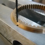 The previous step resulted in having a tooth root aligned with the Y axis, but I want to put my roll pin holes aligned with a tooth so I need to rotate my holes by 360/48/2° which gives me cartesian coordinates of X = 0.0784″ and a Y = 1.1959″ for my two holes.
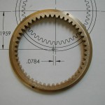 The finished cam gear with the roll pin holes aligned with the gear teeth ready for assembly with the cam ring.
TO DO
- Assembly
Disclaimer and License
All material, including the CAD drawings, relating to the construction of the Hodgson Radial presented on this site is free to use any way you see fit. However, no guarantees are made regarding the accuracy or correctness of the material presented here.

