
- Hodgson Part 035, Crank Cheeks
- Hodgson Part 043, Impeller
- Understanding Crankshaft Counterweights
 I’ve been thinking recently about the crankshaft construction on the Hodgson Radial. I’ve never really been happy with the 5-piece construction and I’m thinking of changing it to a 3-piece crank where the crank cheeks (counterweights) are integral with the front and rear crankshaft sections. The main journal would then be clamped by splitting the upper portion of the crank cheek and using a compression bolt to retain the journal.
Before I could start a new design, I wanted to understand how the current counterbalance weights were arrived at. For internally balanced crankshafts, the counterbalance weight is usually equal to 100% of the rotating weight + 50% of the reciprocating weight. However, while the 50% factor has been proven over time, it is not cast in stone and some experts disagree on the exact value. A good introduction can be found at http://victorylibrary.com/mopar/crank-bal-c.htm. Another good reference is a couple of short articles written by W.B. Richards in 1979 for The Vintage Airplane magazine covering balancing the Warner Radial engines.
Balancing of Radial Engines, W.B. Richards, The Vintage Airplane, 8_1979
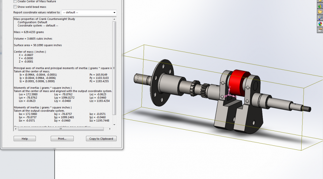
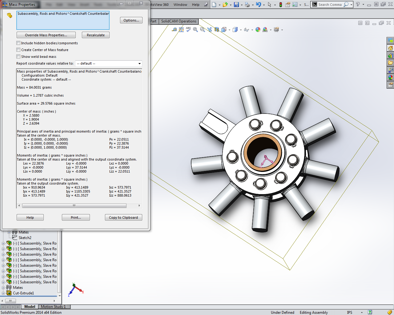
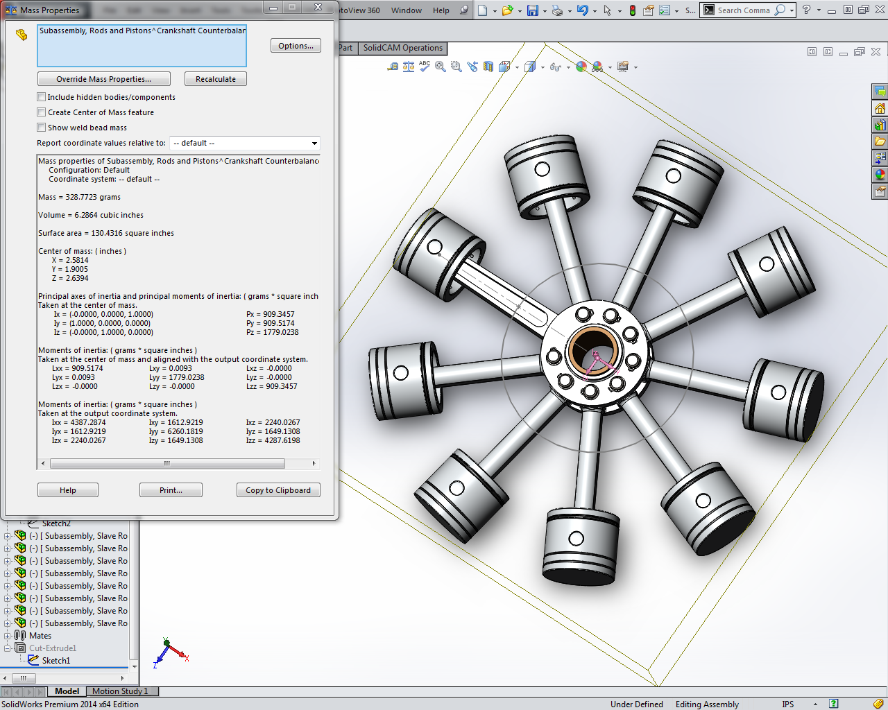
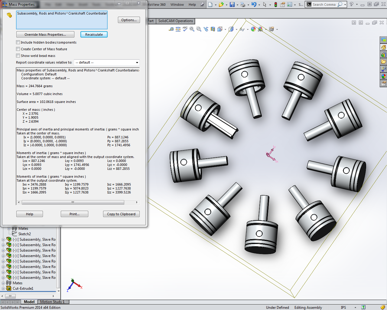
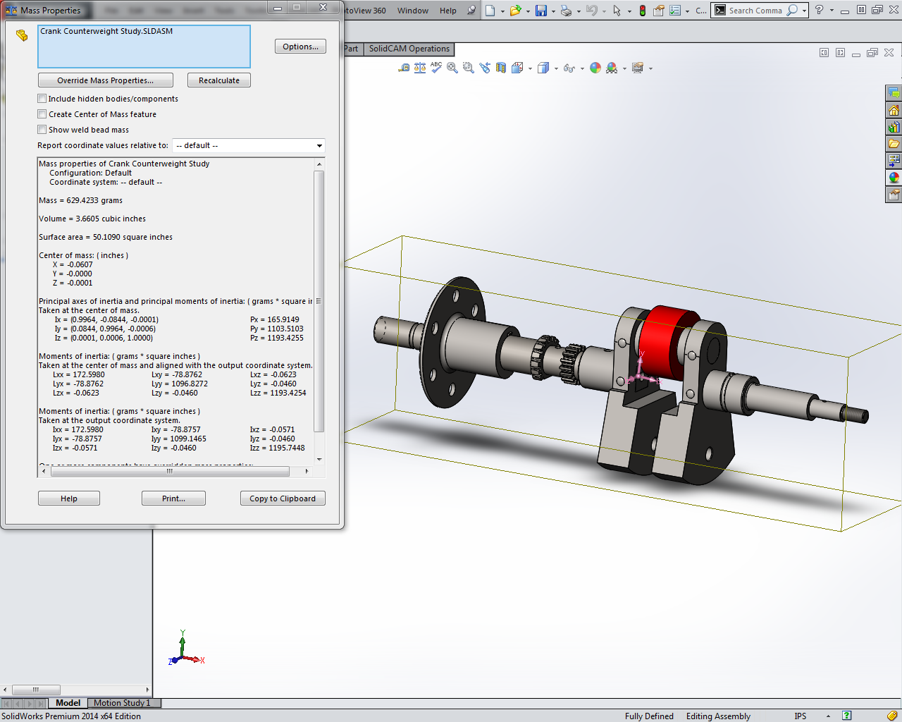
Based on those articles, I made a quick SolidWorks study of the current 5-piece crank. Using the geometric center of the connecting rods, I used SolidWorks mass properties to obtain the rotational and reciprocating component weights of the connecting rod/piston assemblies.
Based on the SolidWorks derived weights, I created an Excel Spreadsheet to calculate equivalent bobweights based on the various factors presented in the papers. I created a bobweight part in SolidWorks and overrode its mass properties setting it to the various calculated weights, and observing the resultant center of gravity location of the assembly. All of the “suggested” weight factors resulted in CG locations 0.012″ to 0.018″ high.
Iteratively adjusting the bobweight and observing its effect on the CG resulted in a bobweight of 194.3g producing a CG inline with the shaft centerline. This equates with a reciprocating weight factor of 45%.
So at this point, I’m left to decide what to do when I create my 3-piece crankshaft. Do I follow the published articles and make my balance weights based on a 0.50 or 0.51 reciprocating weight factor? Or, realizing that this engine has been successfully built in the past with what amounts to a 0.45 factor, maintain this in my new 3-piece design?