
 Like many others building Quorns, I decided to incorporate split cotters instead of splitting the castings as envisioned by Chaddock. One of the major problems with Chaddock’s design is the tendency for the painstakingly bored and lapped holes in the castings to close up when the casting is split and no longer allow the shafts to move freely.
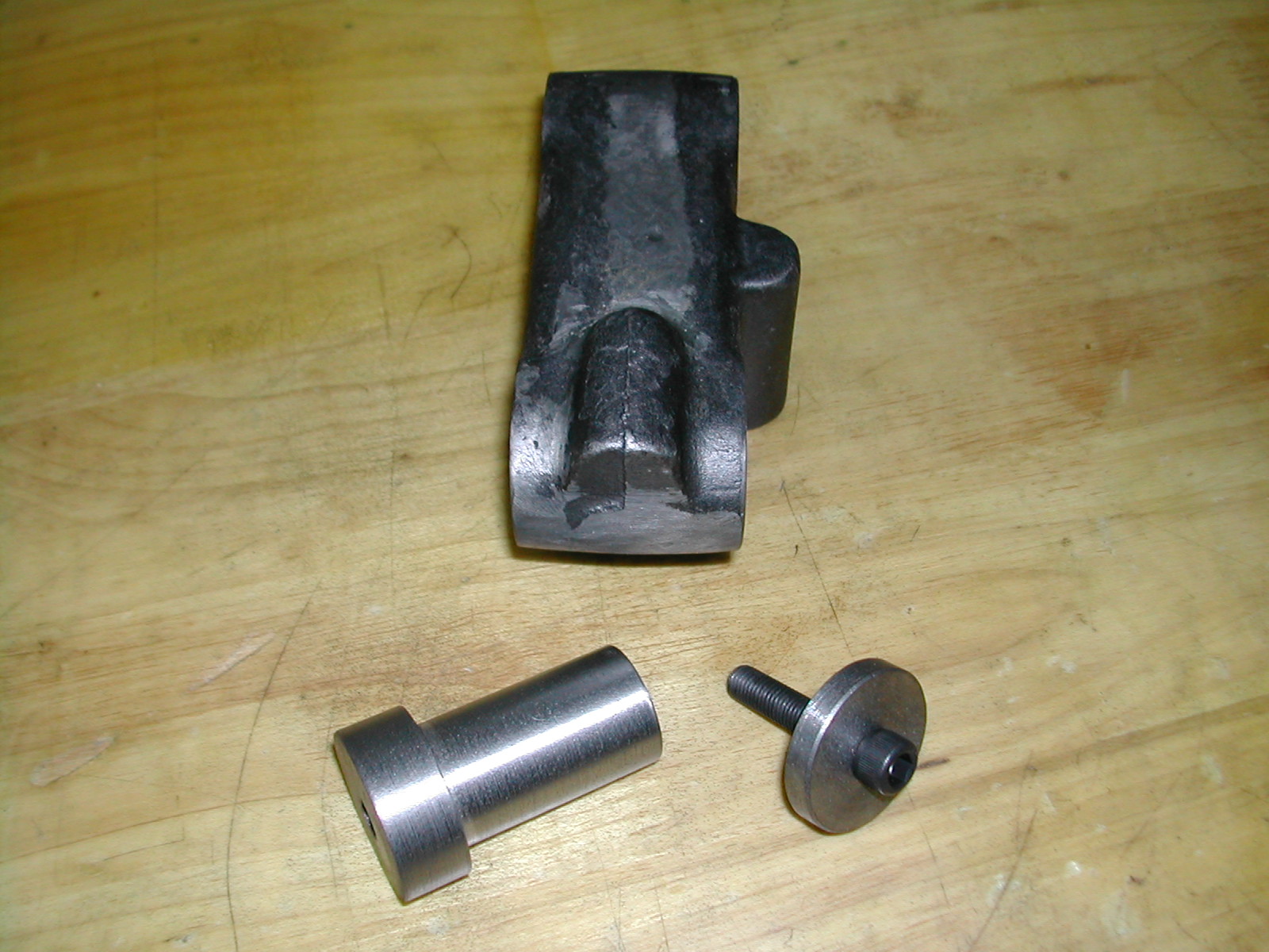
This can be prevented by the use of another method to clamp the shafts with the ball handles. Instead of the threaded stud of the ball handle squeezing the casting around the shaft, the stud is used to pull two formed pins against the shaft squeezing it directly to prevent movement. This page documents my method for implementing this improvement.
 A usual problem I have trying to construct a Quorn while in China is a limited availability of materials and tooling. Most people who have changed to cotters on their Quorn have used 9/16″ material for their cotters. Trying to find a 0.5635″ reamer over here is a lesson in futility. Therefore, I designed my cotters around 15mm material.
The 1.0″ bore cotters are 0.590″ in diameter and use the same 5/16″-24 threaded stud as the original split castings. The cotter centerline is offset from the bore centerline 0.680″. This leaves approximately 0.020″ clearance between the stud and the shaft being clamped.
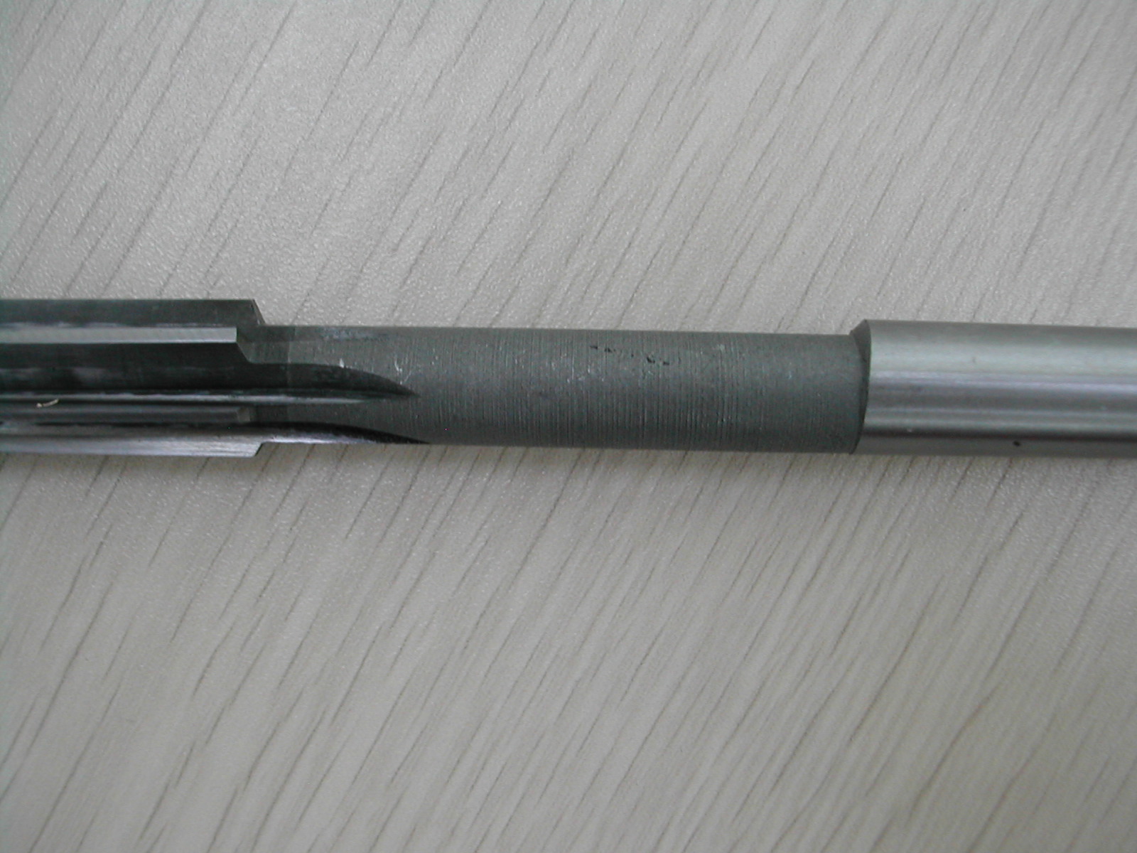 Having decided on sizes, I purchased a 15mm reamer. Over here, there’s no such thing as over/under reamers, just 15mm. Unsurprisingly, it actually cut 15.13mm and the surface looked like it was whittled with a pocket knife. Look at how offset the turned down shank is in relation to everything else! A little time spent with a diamond hone and I got it to cut about 15.04mm with an acceptable surface finish.
Finding 15mm brass was the second act of this comedy. I finally found some “16mm” material that was really 15.6mm and had to turn all the pins to size. Looks like I didn’t really need to spend so much time getting the reamer to the correct size after all.
 Some people choose to drill and ream the cotter hole in the castings before boring the shaft hole. They then cut the cotter in-situ when boring the shaft hole. This creates a chicken-and-egg problem. Without the shaft bore, where do you situate the cotter hole? I chose to bore my shaft holes first and then drill for the cotters.
Doing things this way means I need a good way to cut the coves on the cotters since they won’t be cut at the time the shaft hole is bored. Luckily, Richard of the Quorn Owner’s group has already laid the foundation for the solution.
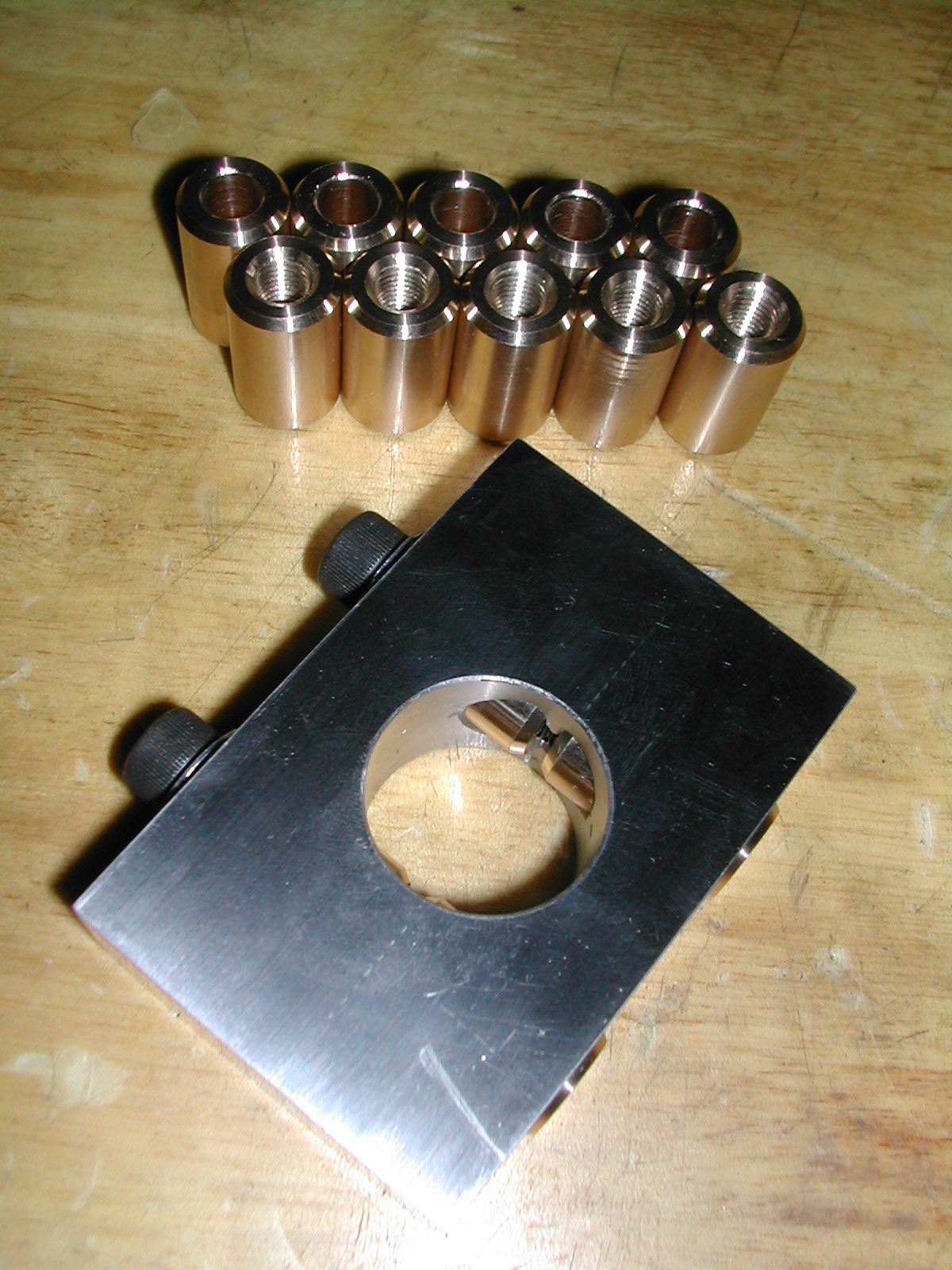
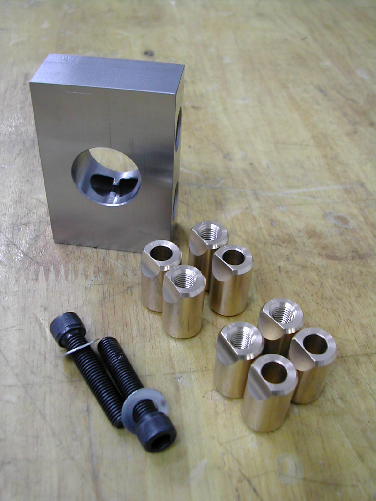
I changed Richard’s design a little. I decided to bore two sets of cotters at the same time. This makes setting-up the jig very easy and it also allows you to check the dimension of the cut cotters in the jig. Here’s the pin blanks for the 1″ bore cotters and the boring fixture for the same. The 1-¼” cotters will require a different fixture.
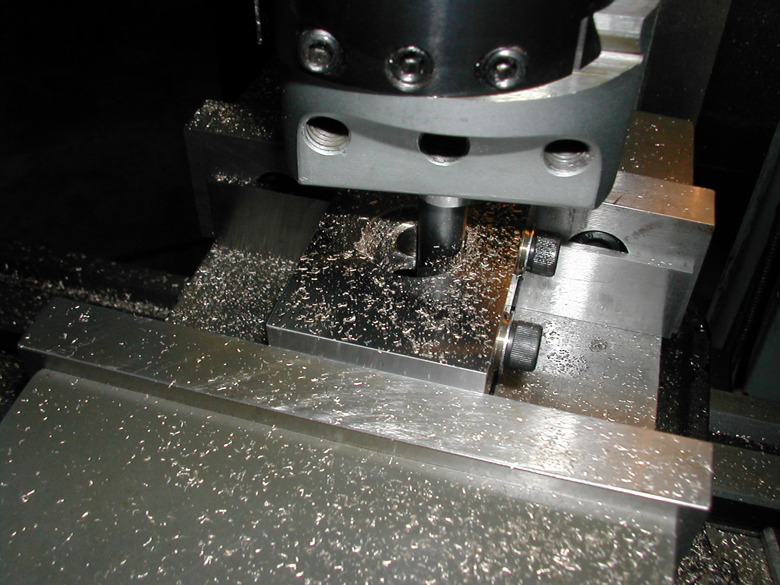 Setting up the fixture is simple — just locate the center in both directions. Here I’m are boring the first two sets of cotters.
 With two sets of cotters in the jig, it’s simple to use a telescoping gage to check the bore diameter. I’m shooting for 1.000″ +0.001/-0.000 since that’s the diameter of my ground shafts.
Since there is very little coming off the brass, and brass machines wonderfully, boring subsequent pairs of cotters is very easy. Leaving the fixture securely clamped in the mill, just remove the clamp bolts and insert two new pairs of blanks. You won’t need to re-adjust the boring bar. One pass at the previous final setting will complete the next pair.
 Here’s a better shot of the fixture and four sets of 1.0″ bore cotters. If you enlarge the photo, you can just barely see the matching numbers on each cotter set. It’s probably not needed since I took care to make sure the fixture was symmetrical, but it takes no time at all to engrave them.
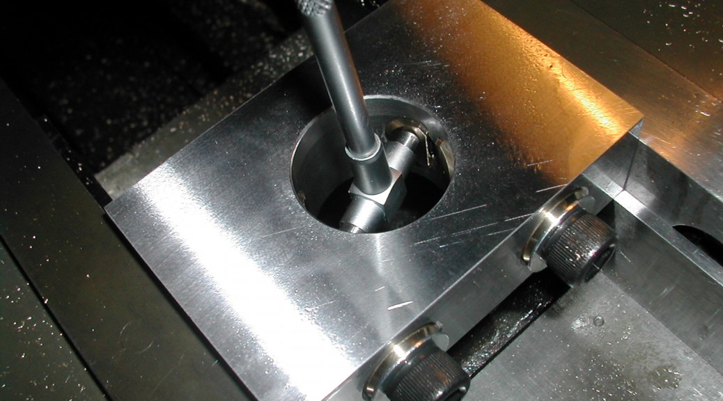
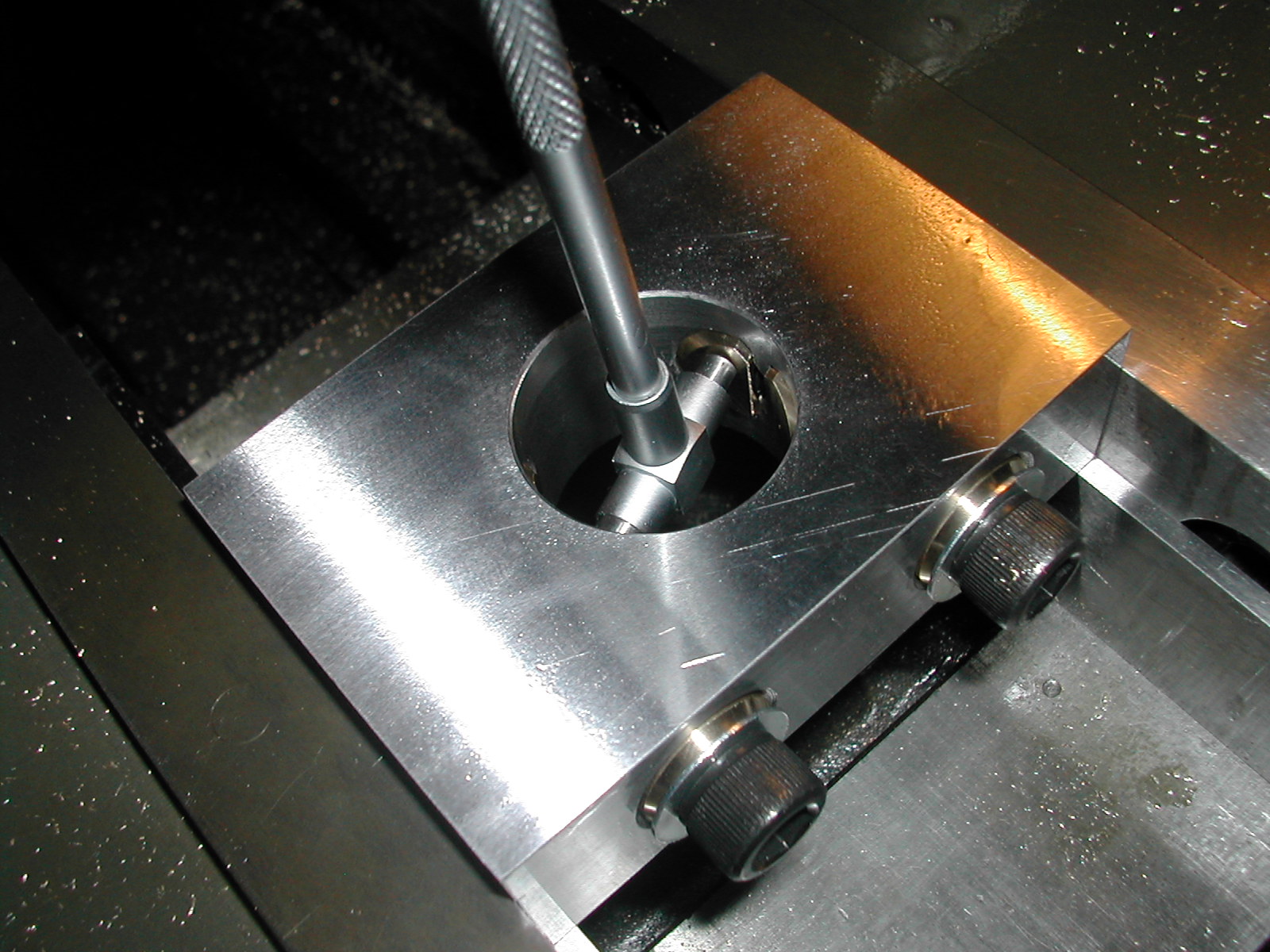
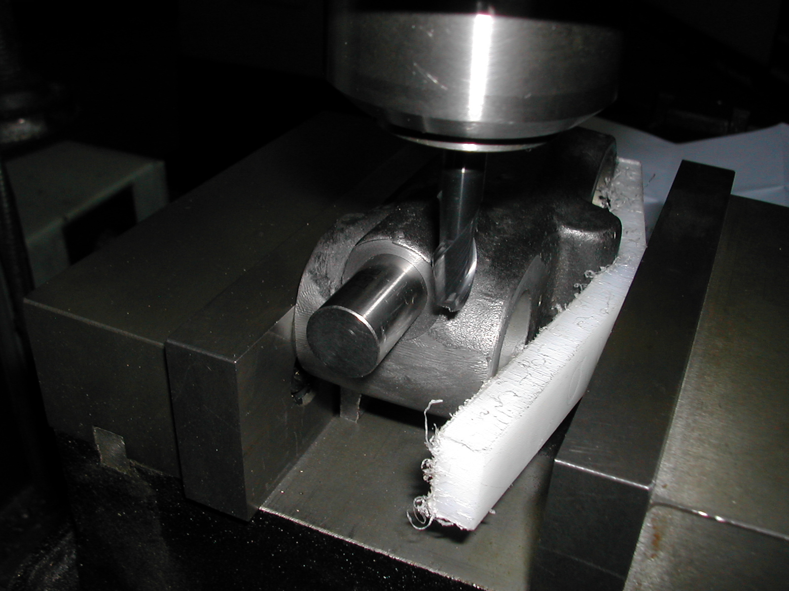
 With the cotters themselves all finished, here’s the process for modifying the castings. Since the bores in the casting are complete at this point, I made a plug out of some scrap cast iron I had around. Using this plug will prevent an unbalanced cut when drilling and reaming the cotter hole and help insure it’s accuracy. It will also prevent chipping and burrs at the intersection of the two bores. This area would be hard to deburr by hand afterwards.
When I say scrap cast iron, I really mean crap cast iron. This was locally sourced here in China and was supposed to be “fine-grain”. It had so much porosity, inclusions, and hard spots, it’s probably only good for ballast in a ship which is probably where it came from!
 I turned the boss on the end of the plug to a known dimension at the same time as the 1.000″ section. This insures that it is concentric with the bore when inserted in the casting and I can use it to indicate the centerline of the casting bore.
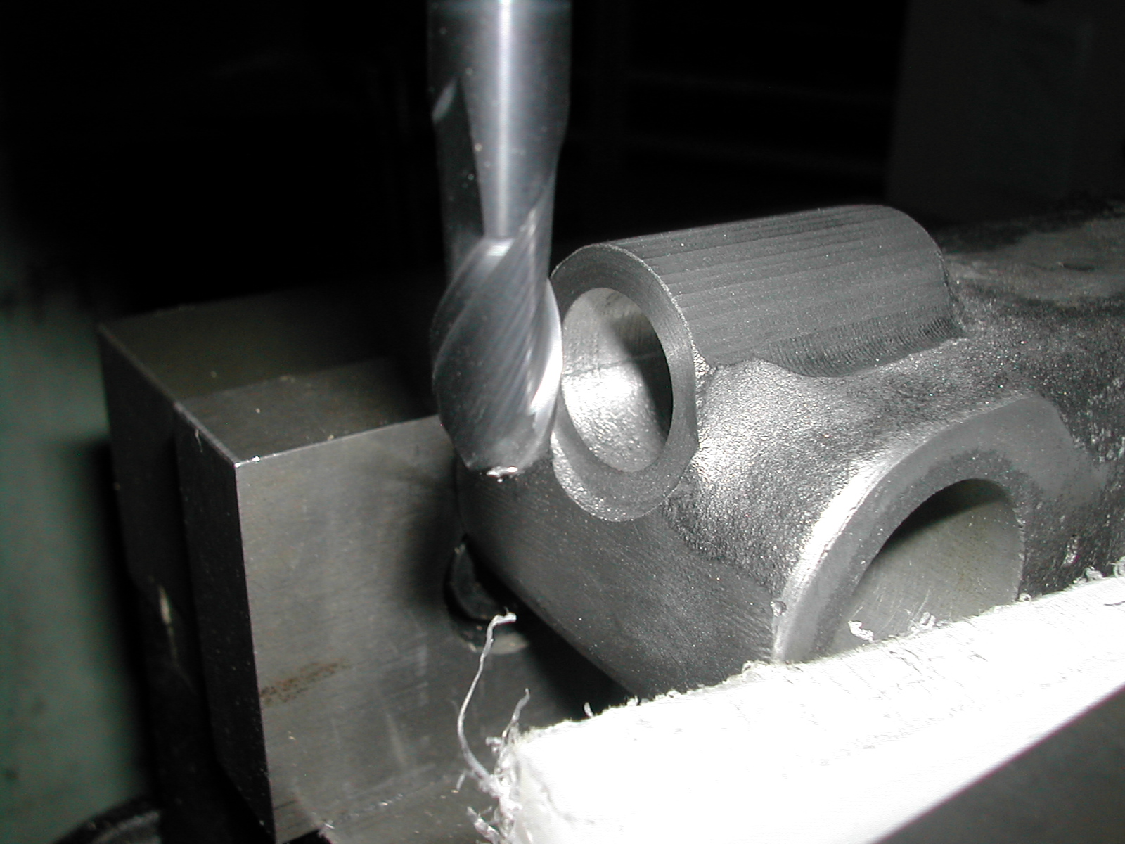
 Once the bore’s centerline is found, I offset 0.680″ and visually center on the boss in the other direction. I dropped in a end mill to get a flat surface to drill from and to also give me a better visual indication of the center position.
This isn’t the finished counterbore size so I can move my position a little one way or the other if needed at this point.
 At this point, it’s pretty straight forward to drill and ream for the cotters.
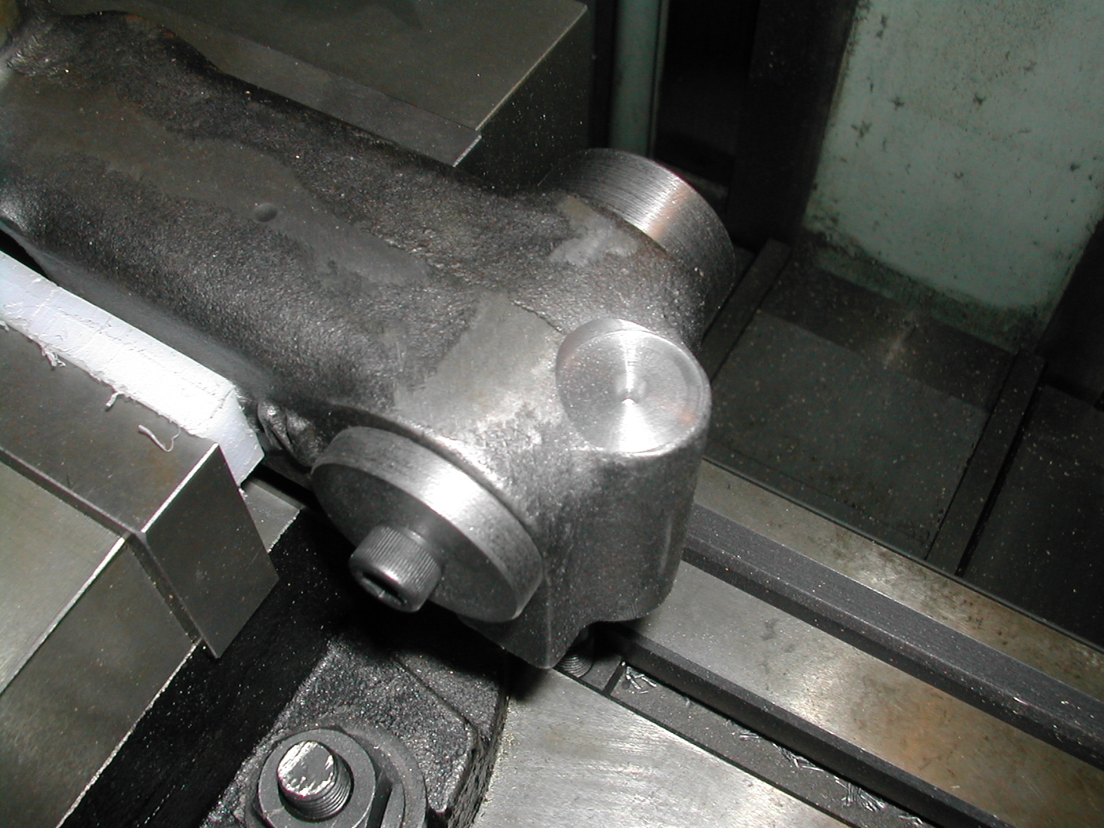
 Now, I’m going in with the final counterbore to clean up the surface. Since the casting bosses were designed for a 0.875″ offset and split cotters are usually at less than this dimension, the bosses ends up looking lopsided when split cotters are used on the Quorn. Carl Carlson of the Quorn Owner’s Group noticed this and profiled the bosses concentric with the cotter bores.
I plan on doing the same so here I’m spotfacing with a cutter that’s the same radius I’m going to make the casting bosses.
Here’s the finished bore. Notice how sharp and burr-free the bore intersection is. The plug can be turned slightly and used again for the next casting.
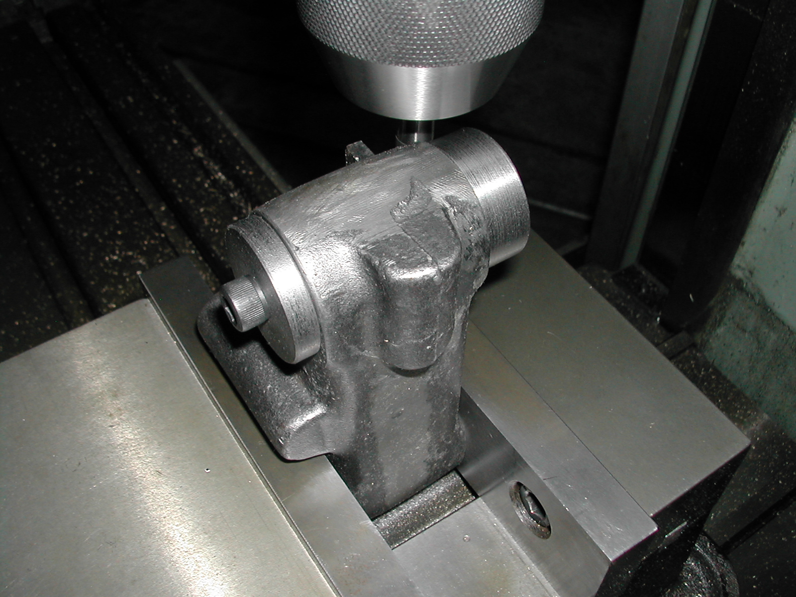
 I’ve re-clamped the part in the vise and I’ve used a pin with a edge finder to locate the center of the cotter bore in X and Y. With the ball-nose endmill chucked up, I’m locating center in the Z direction. A few minutes with Excel, and I’ve got coordinate locations to profile the boss.
 Approximating the new boss radius with a 0.040″ chord length, the scallops are noticeable but will easily file out. The cotter bores are 15mm and the new boss is and 11mm radius. That gives me about a 0.14″ wall thickness which should be enough.
For the 1-¼” wheelhead column, I’ll need a new cotter boring fixture, but I think I’ll be able to use the same 0.590″ (15mm) cotters and 0.680″ offset.
Disclaimer and License
All material, including the CAD drawings, relating to the construction of the Quorn presented on this site is free to use any way you see fit. However, no guarantees are made regarding the accuracy or correctness of the material presented here.
CAD Files Used On This Page (AutoCAD 2008 Format)