
- Hodgson Part 021, Front Bearing
- Hodgson Part 022, Rear Main Bearing
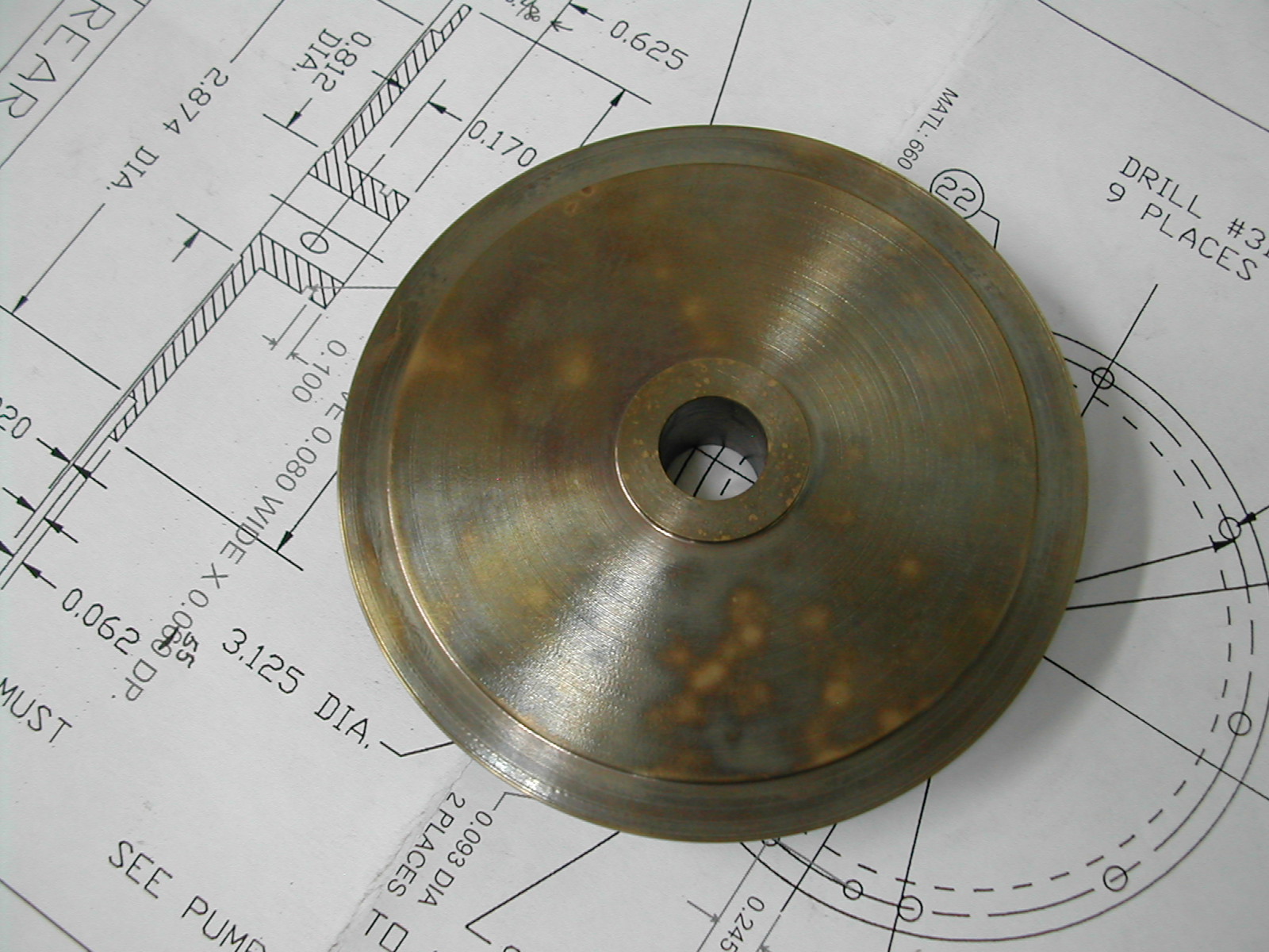
 For the rear bearing, I chose C63000 nickel aluminum bronze (known as QAL9-4 bronze here in China). This material has high strength because of the added nickel (needed for the thin mounting flange) and good wear resistance. The downside is this material is very “grabby” and tends to warp if you get it hot. Therefore, I’m going to machine it in two phases with a stress relieving operation in-between.
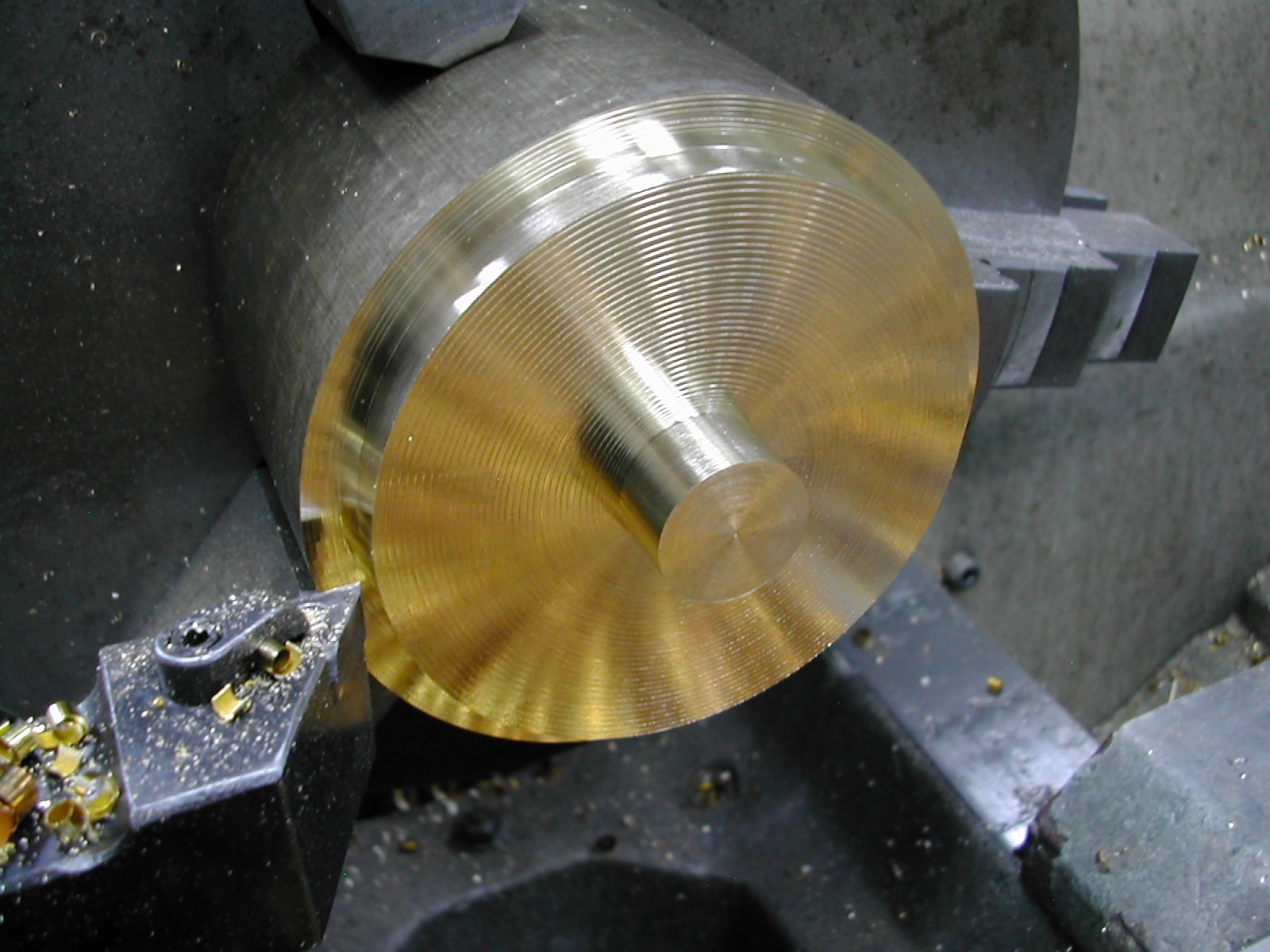 Here I’ve rough turned the aft face of the rear bearing leaving about 0.050″ on all surfaces to finish after stress relieving. I’ve turned the center boss to 23.5mm so that I can chuck it in a collet for the first part of the finishing operations.
 The bore is also roughed out before the blank is parted off from the stock. Be careful of the parting operation as it can generate a lot of head and subsequently warp the part. Use a sharp tool and lots of coolant.
 Seems like a lot of material to waste.
 Here is the rough part after 2 hours at 400°C. This stress relieving operation should prevent any warpage of the thin sections during final machining.
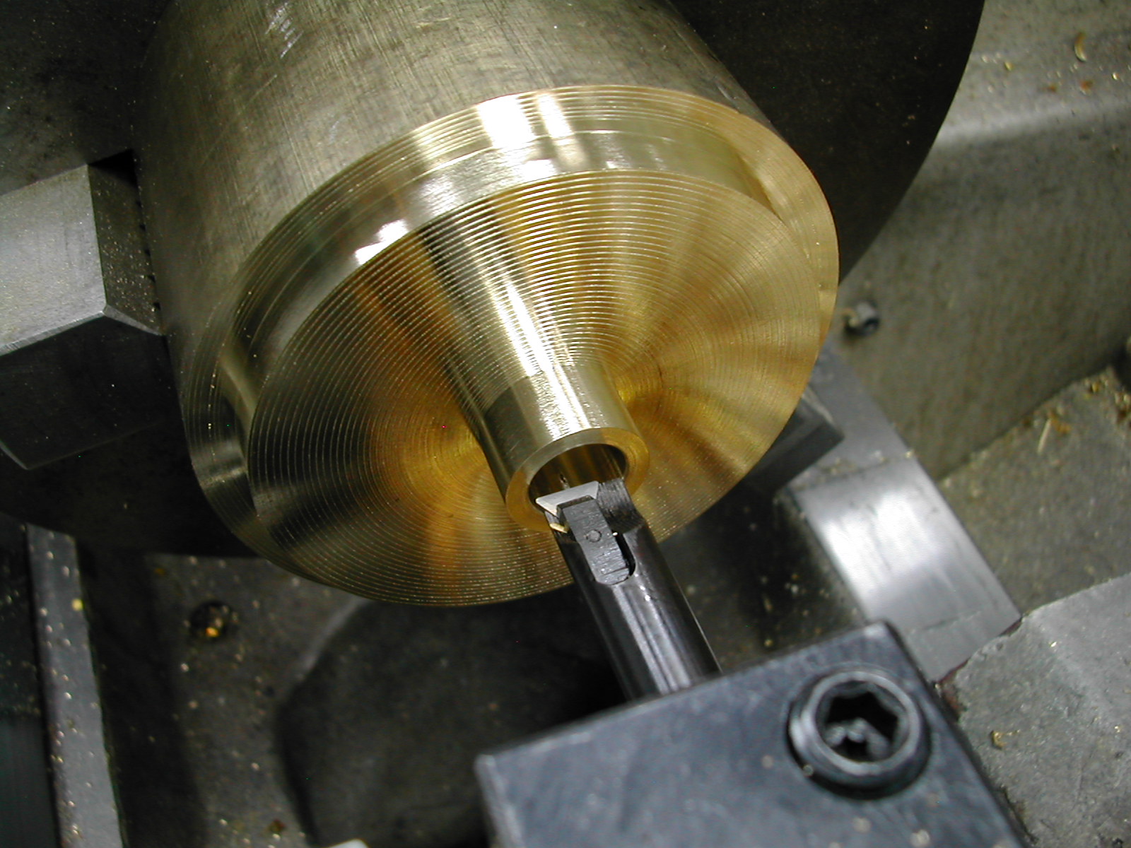
 With the 23.5mm boss chucked in a collet, the bore is finished. The bore was checked with a 0.562″ and a 0.563″ pin gage. The 0.562″ gage passed and spun freely while the 0.563″ gage did not enter.
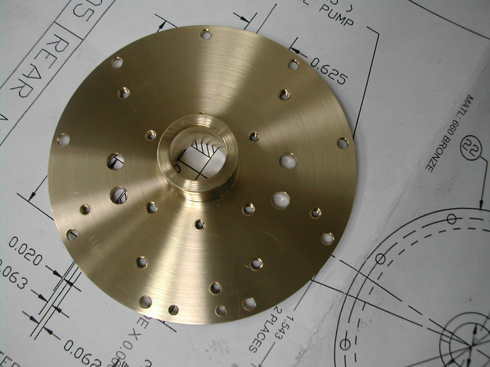
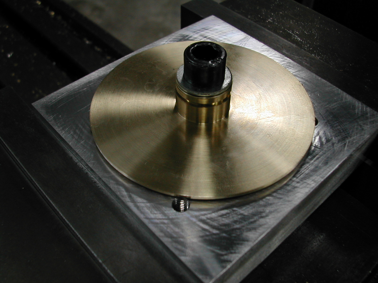
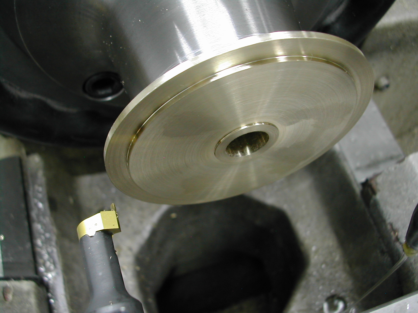 The complete front side of the rear bearing is then finish machined including the flange and the 3.374″ O.D. in one chucking to insure concentricity with the bore.
 A sharp tool and slow speeds were needed to prevent this thin part from chattering.
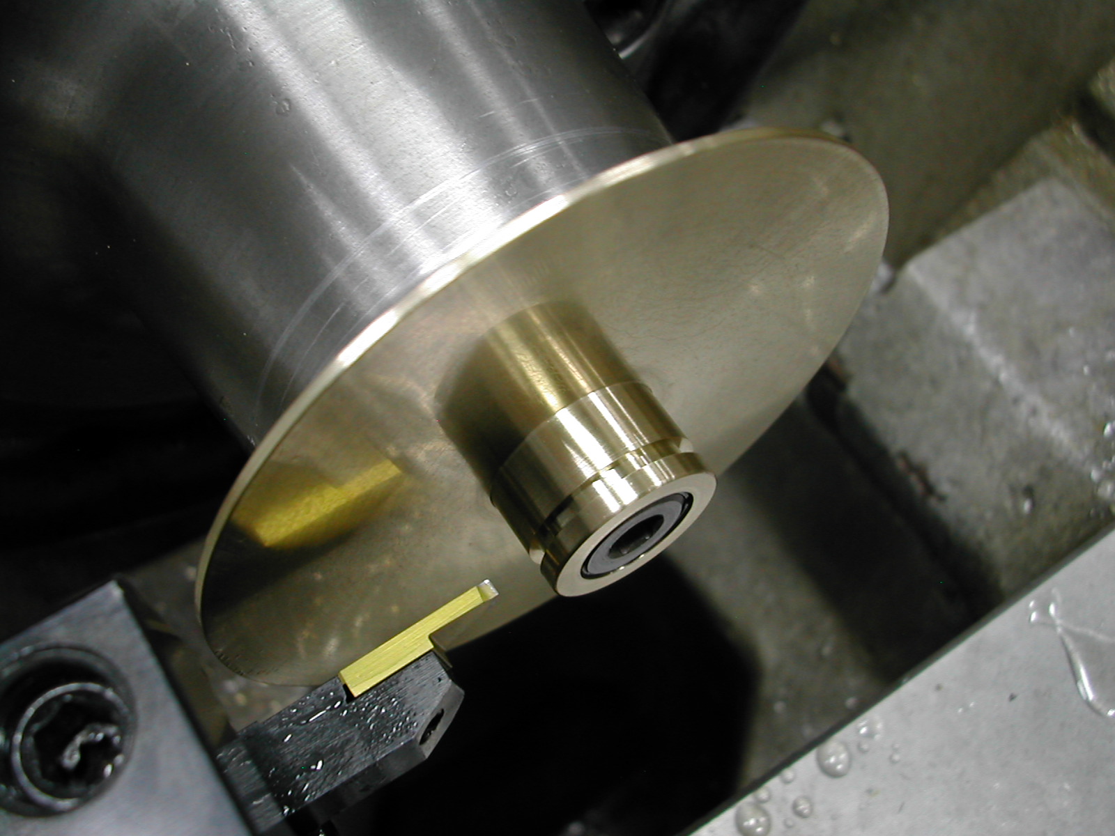
 A 0.562″ spud arbor was turned in-situ. This arbor was then tapped for a 1/8″ pipe plug and split with a hacksaw without removing it from the collet.
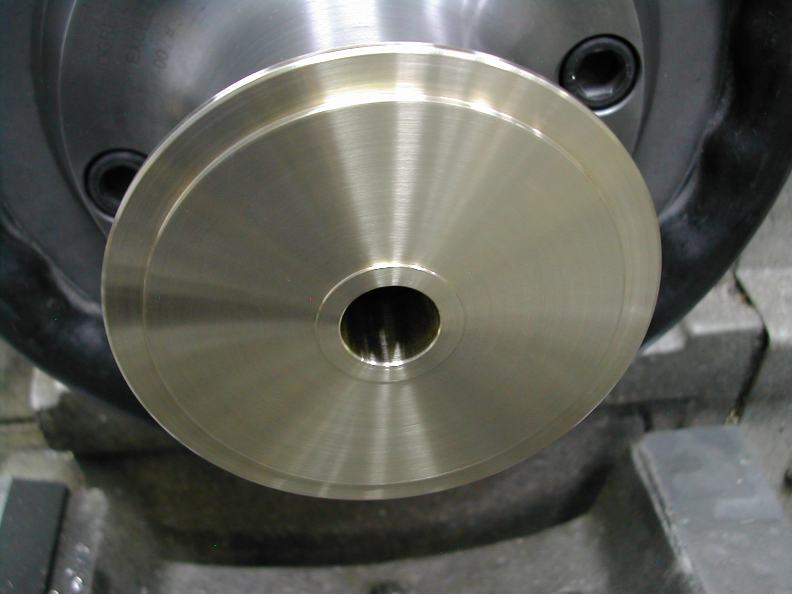
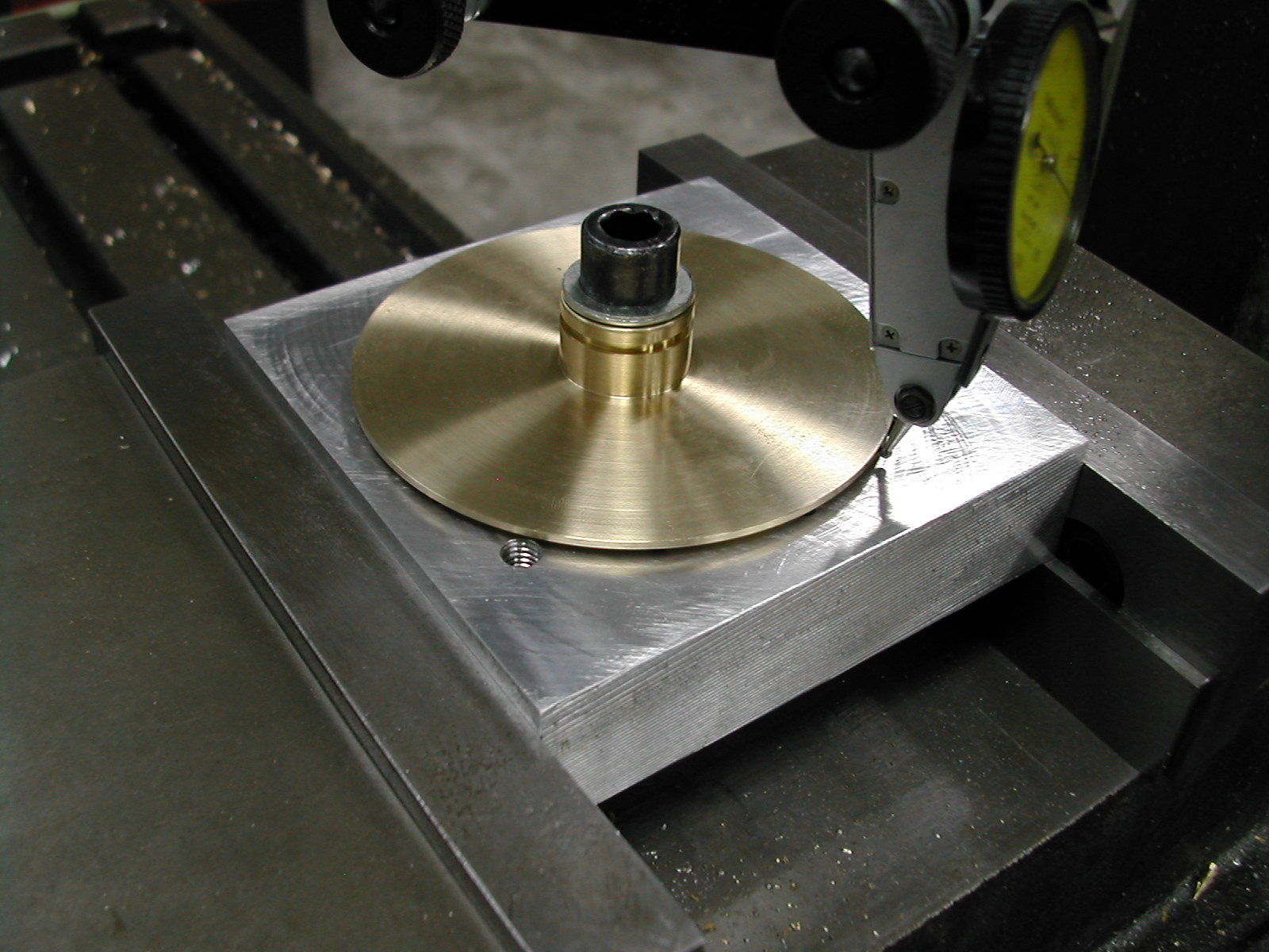
The part was then mounted on the arbor and the runout of the O.D. and the 0.062″ step previously turned on the backside was checked. Runout in both cases was less than 6µm.\
 With the part running true, the oilpump boss O.D. and the aft face were finish turned. An 0.080″ wide by 0.055″ deep O-ring groove was added 0.1″ from the end of the boss for an AS568A-017 O-ring.
One final step before removing the part from the lathe was to lap the face of the bearing with some 800 grit wet-or-dry sandpaper backed by a ground steel parallel to insure a flat face and a good seal with the oilpump housing.
Before proceeding on to hole drilling, you should have completed the oil pump housing up to the point of drilling the gear shaft holes so that they can be align reamed in both the bearing and pump housing.
You should also consider completing the turning operations on the front bearing so that can be drilled in the same mill setup.
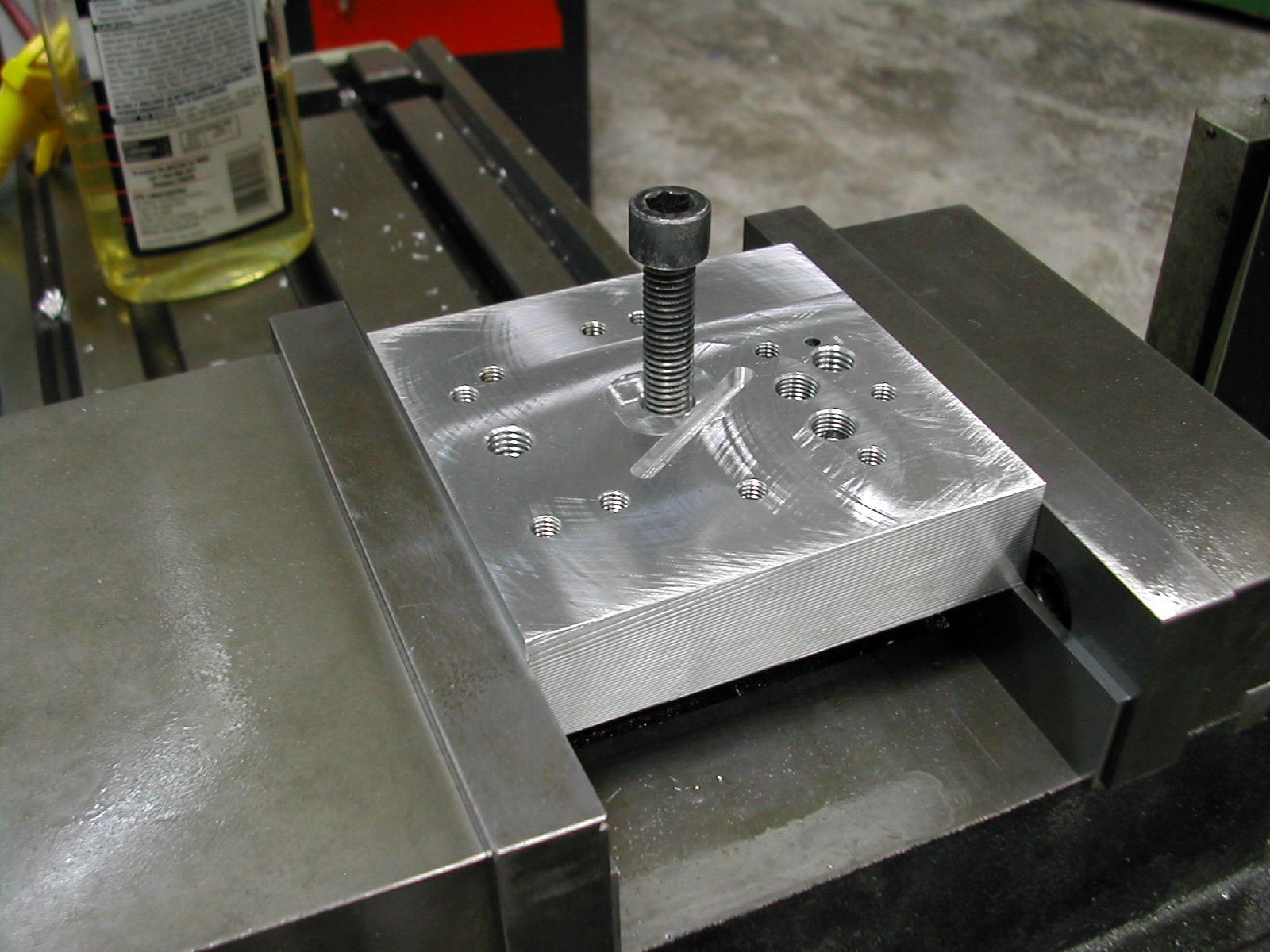 A simple drilling fixture for the bearing was made from a scrap of aluminum. The scrap was faced after clamping in the vise to be sure it was perpendicular to the mill spindle and a M10 hole was tapped near the center.
A 0.020″ recess was milled around the tapped hole to clear the boss on the backside of the bearing so that the majority of the bearing would be in contact with the tooling plate.
 The rear bearing was then clamped to the tooling plate with a M10 SHCS and washer.
 Now is a good time to verify that the oil pump housing can be fit to the rear bearing without loosening the mounting bolt.
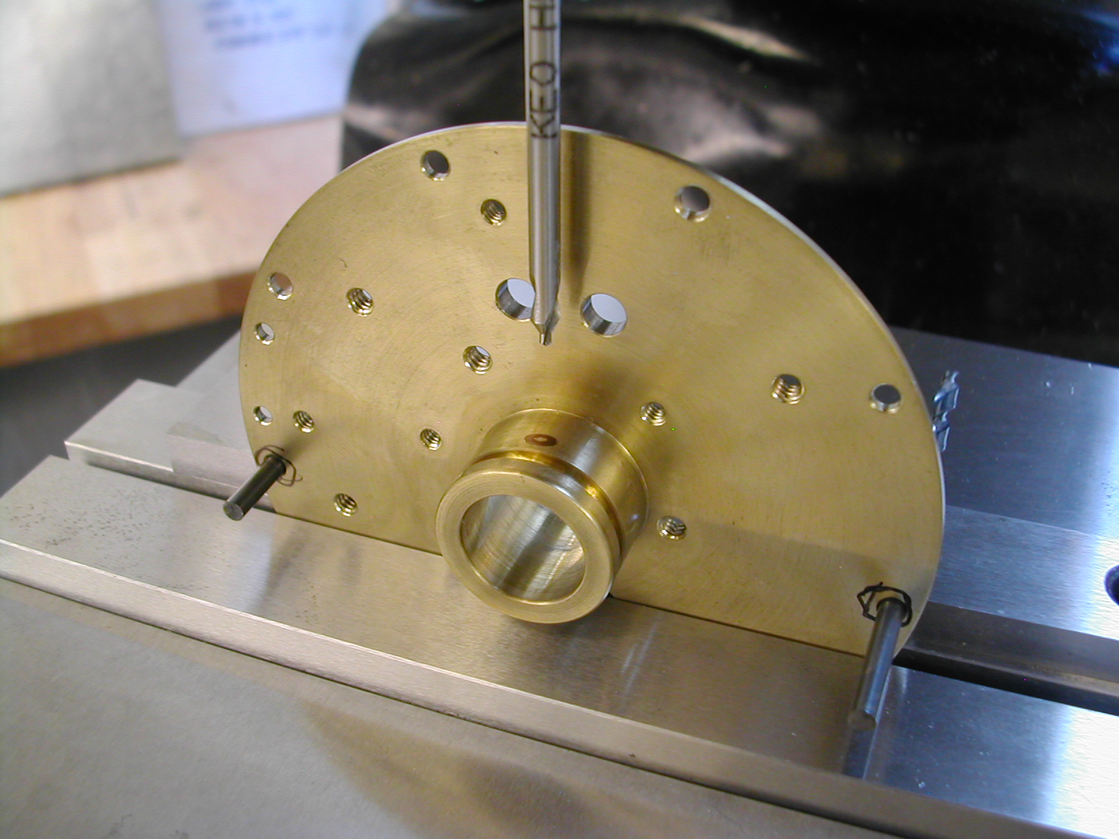
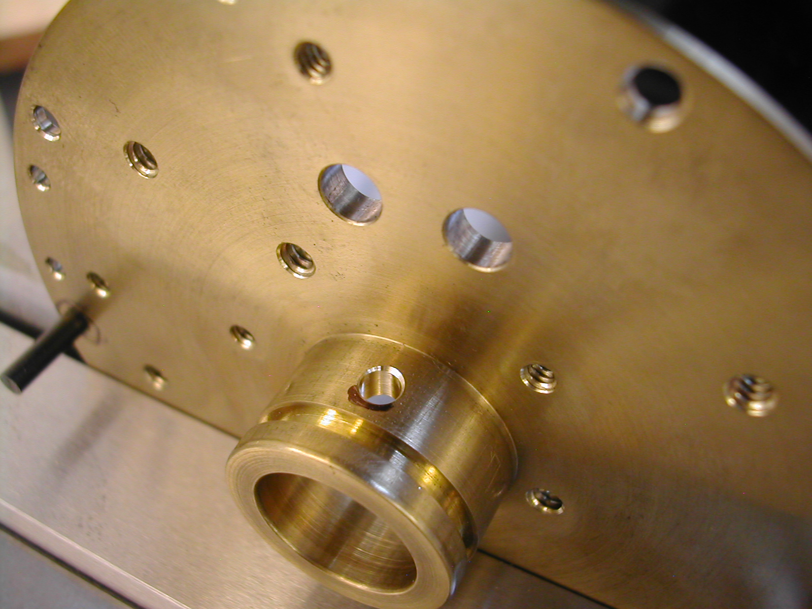
 The center of the bearing is then located by indicating the bearing O.D.
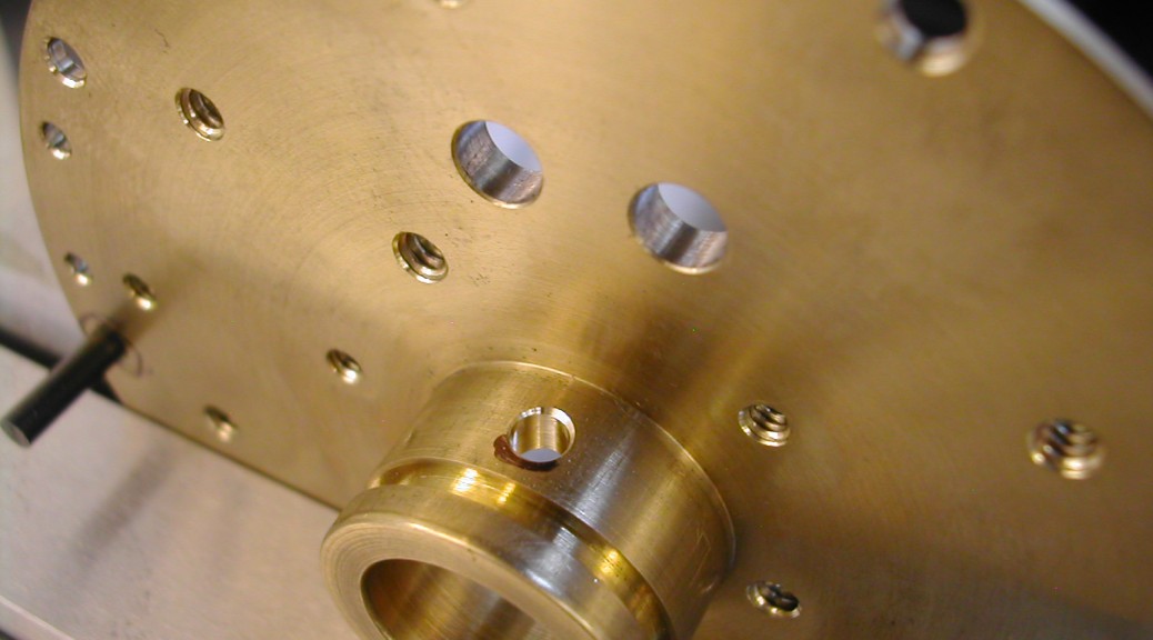
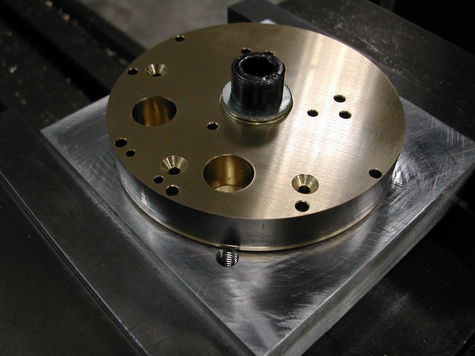
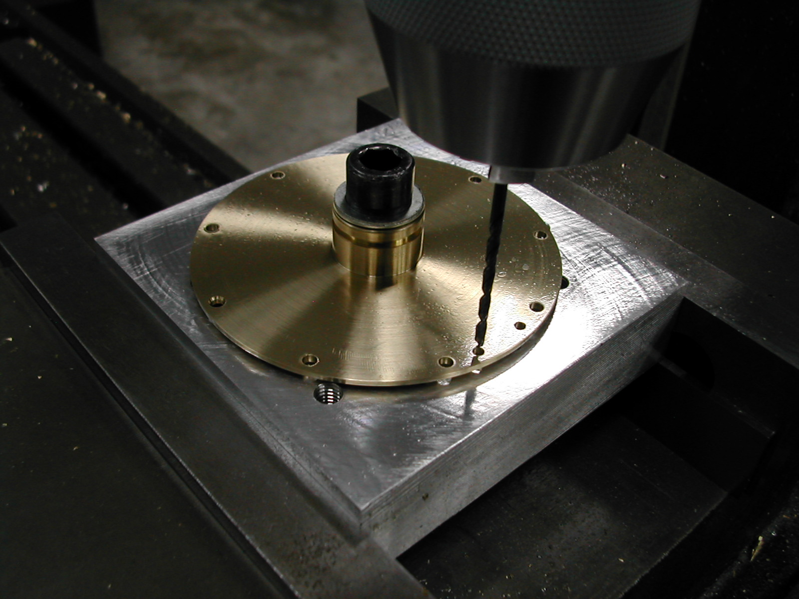 All of the #4 clearance holes in the flange are drilled including the two 0.093″ oil drain holes.
I had previously drilled the oil pump housing on this fixture so I’ve rotated all the hole positions 90° so that (hopefully) I will not hit a previously drilled hole in the tooling plate and knock my drill bit off-course.
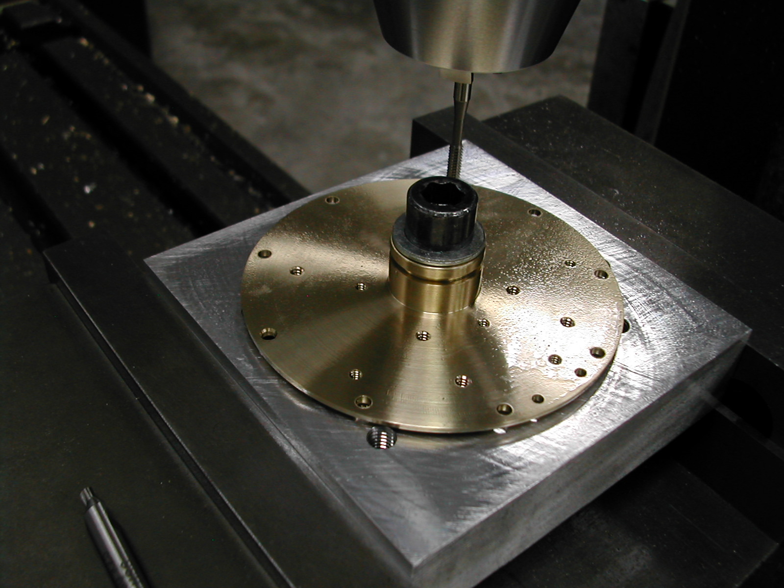 Here, all of the #4-40 and #6-32 holes have been drilled and tapped. I’ve added an extra #4 screw to the sump tube arm of the oil pump, so there’s and extra #4-40 tapped hole here as well.
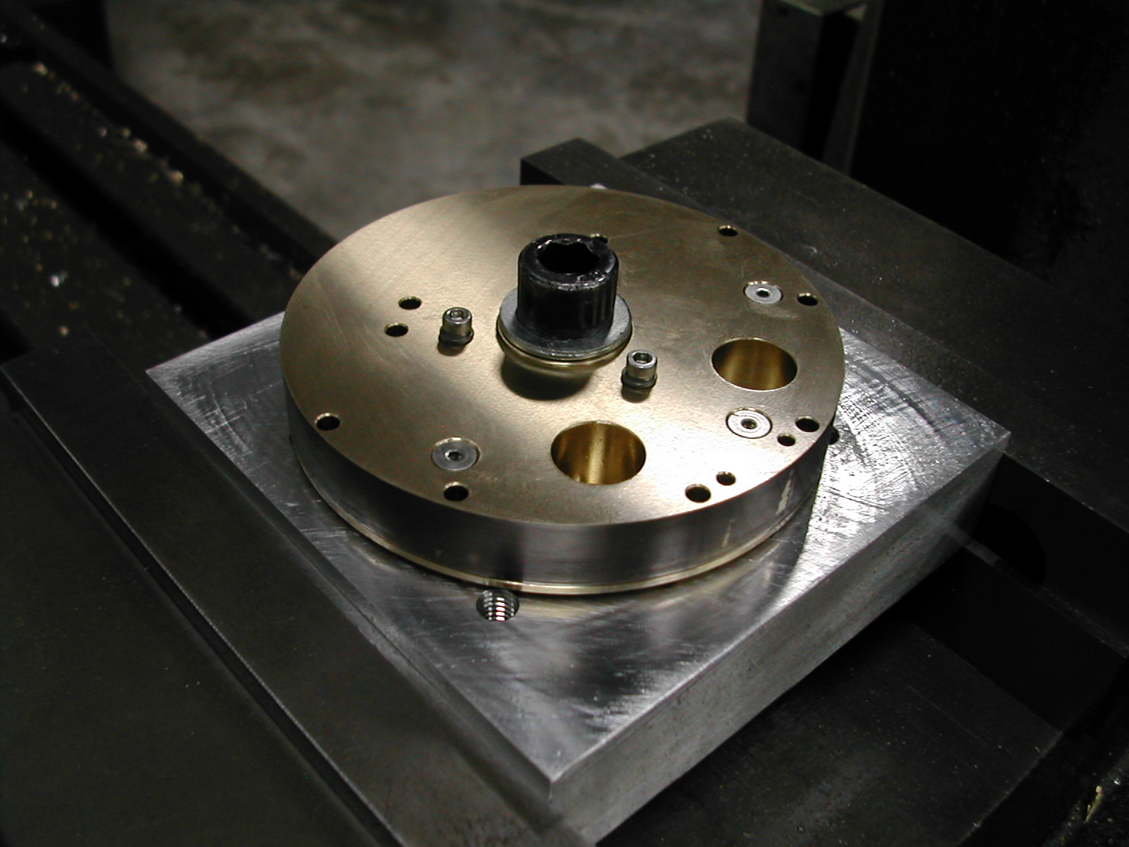 Without removing the rear bearing from the fixture and loosing the location, the oil pump housing is attached. Here you can clearly see the extra #4 flat head screw on the bottom of the oil pump housing.
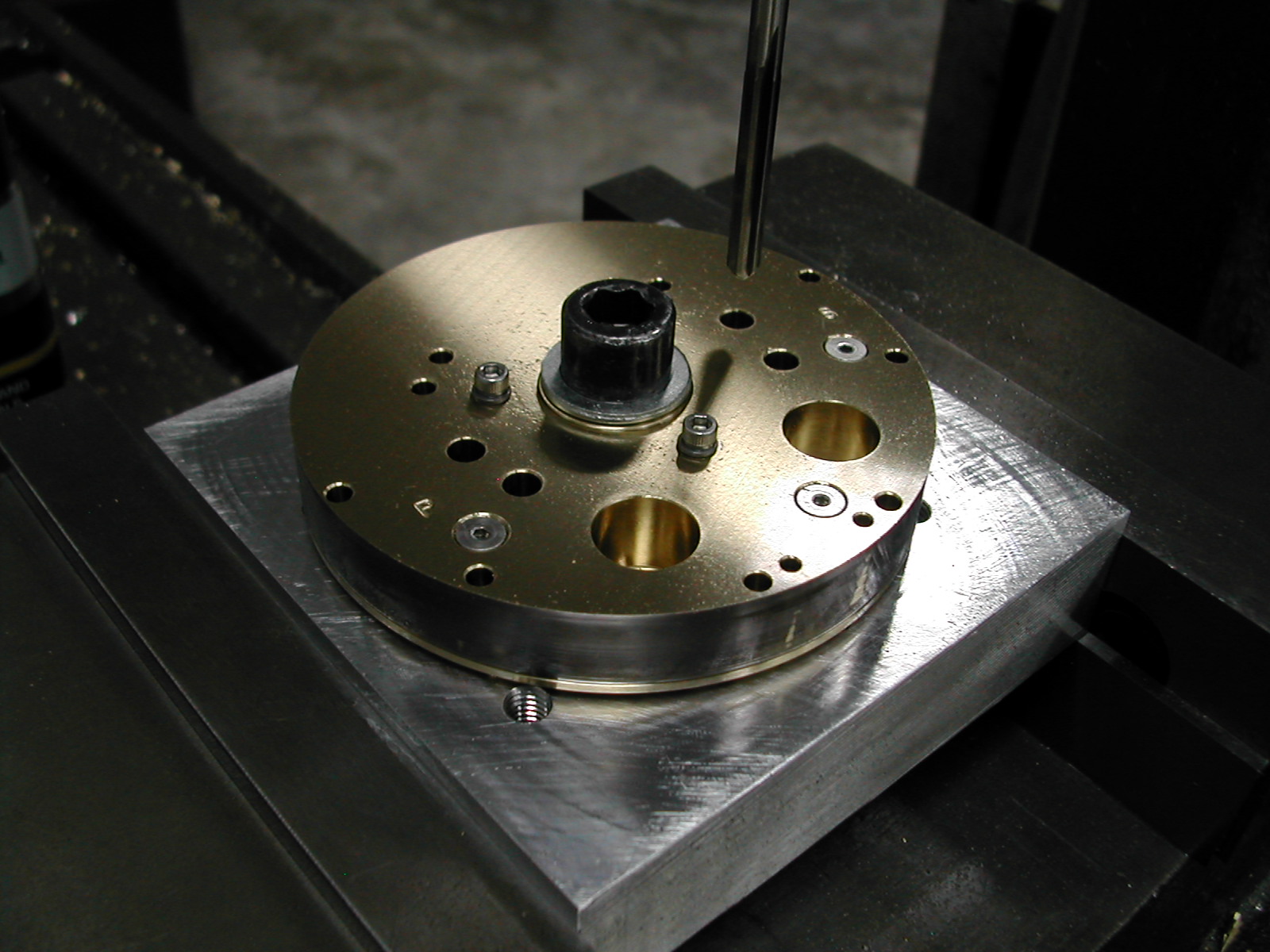 The last machining operation while mounted on the tooling plate is the four 0.188″ reamed holes for the pump gear shafts.
 To put in the crankshaft oil passage 10° off the horizontal, I’m using a couple of #31 drills, in appropriate perimeter mounting holes drilled previously, resting on a parallel to lift the bearing boss clear of the front vise jaw.
I then indicated the center of the bearing, and offset the 0.170″ dimension from the face of the boss.
 A long center drill will deburr the outside of the oil passage and a 1/4″ ball rotary burr used very carefully cleans up the inside.
Here is the finished rear main bearing ready for installation.
Disclaimer and License
All material, including the CAD drawings, relating to the construction of the Hodgson Radial presented on this site is free to use any way you see fit. However, no guarantees are made regarding the accuracy or correctness of the material presented here.
Links Used On This Page