
- Hodgson Part 021, Front Bearing
- Hodgson Part 022, Rear Main Bearing
 For the front bearing, I chose C63000 nickel aluminum bronze (known as QAL9-4 bronze here in China). This material has high strength because of the added nickel (needed for the thin mounting flange) and good wear resistance. The downside is this material is very “grabby” and tends to warp if you get it hot. Therefore, I’m going to machine it in two phases with a stress relieving operation in-between.
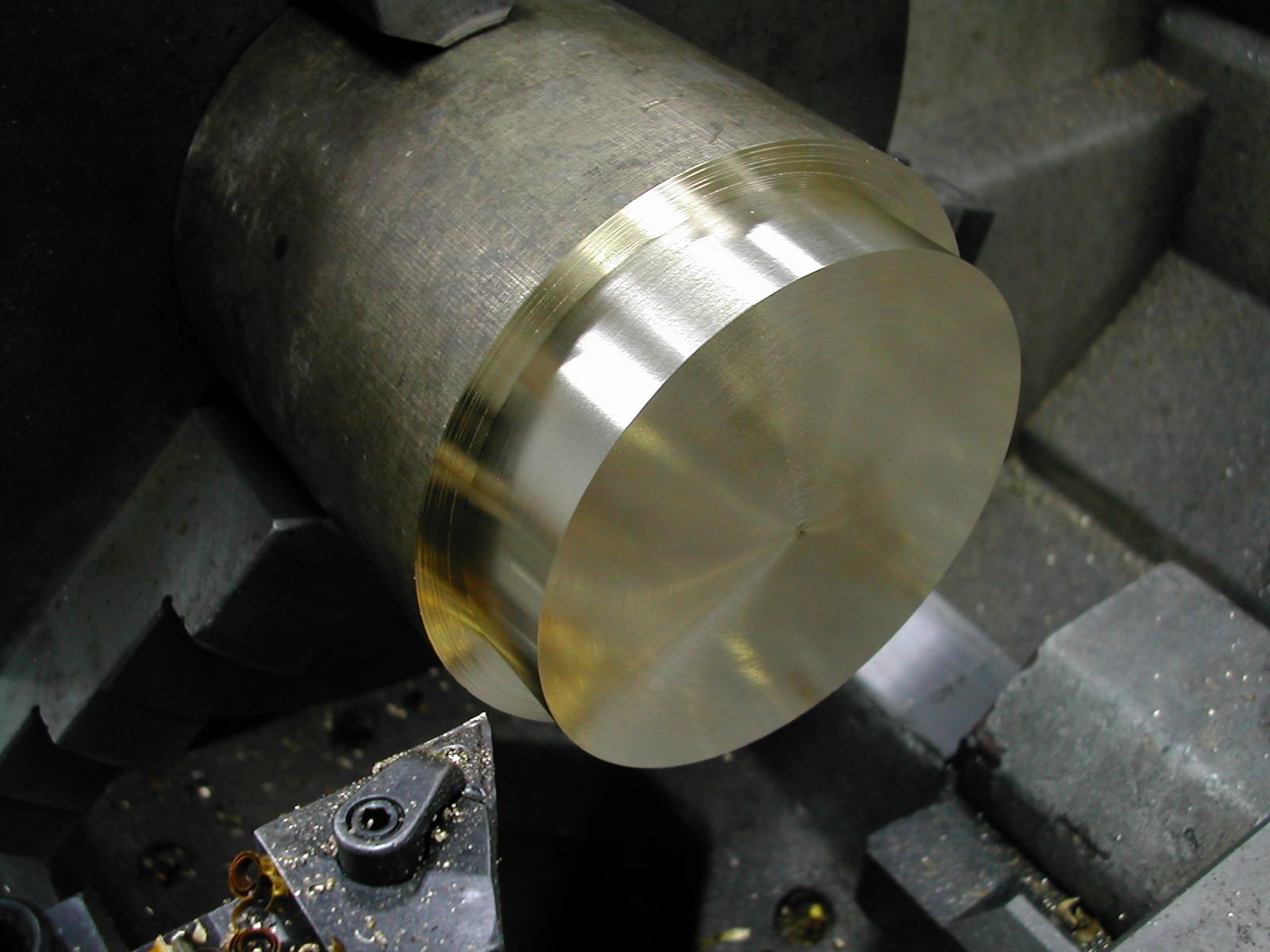 First I began by facing the end of the stock and rough turning the O.D. For these roughing operations, I’m leaving about 0.025″ on all surfaces to clean up after stress relieving the part.
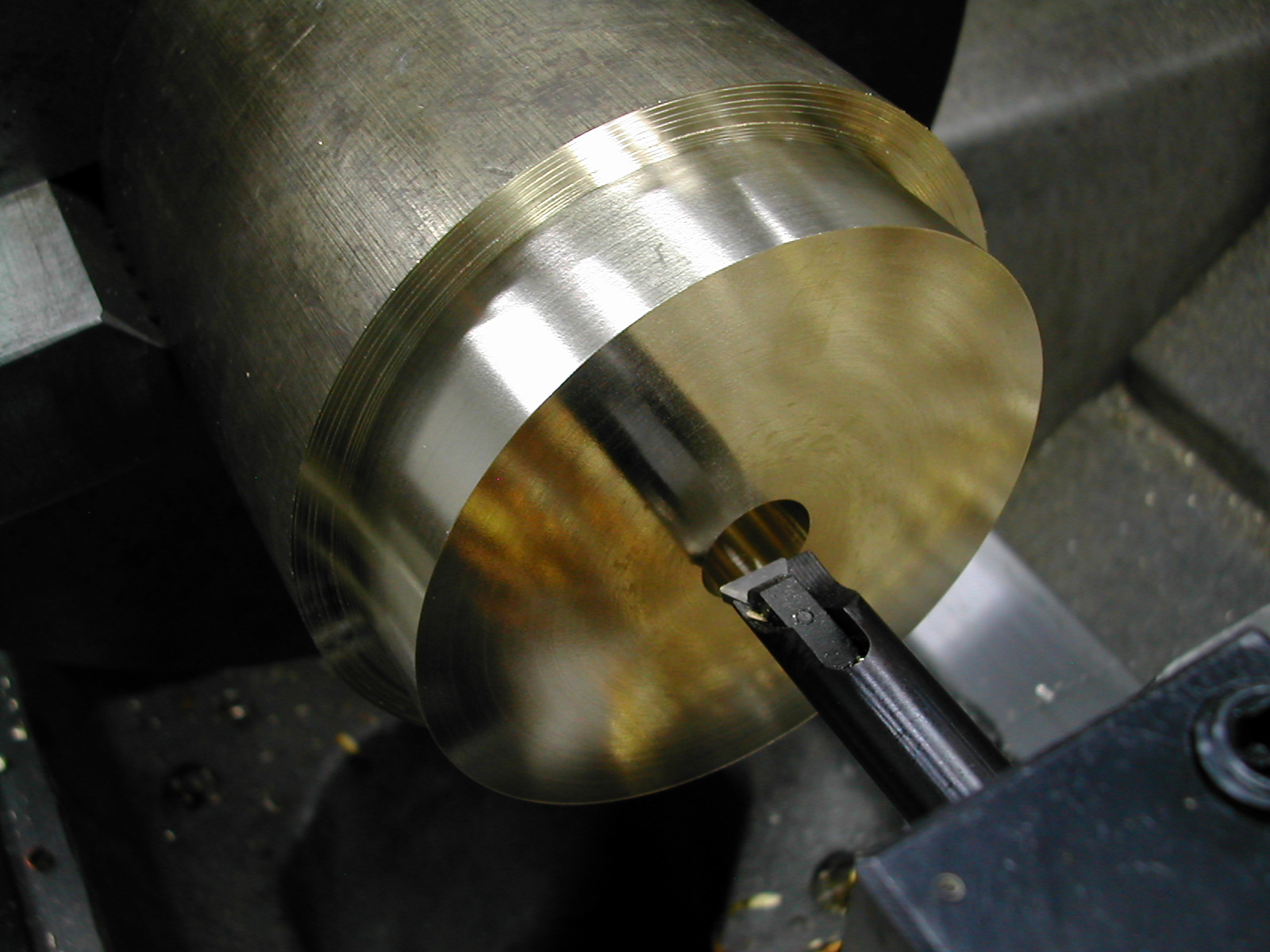 The rough bore is added next.
 Then the front side is blocked out.
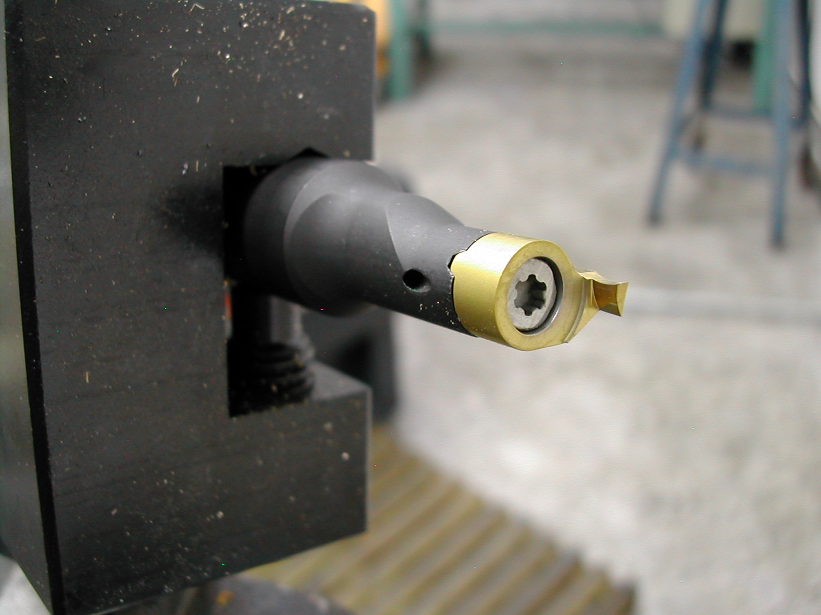
This is a great little Sandvik face grooving tool (insert MB-09FA150-02-14R). I didn’t have a left-handed version, so I’m going to mount the tool upside-down and run the lathe in reverse so I can rough the ridges on the face of the bearing.
 While I’m leaving stock on all surfaces for finishing after stress relieving, I turned the center boss to a known dimension; 23.5mm in this case since I have a collet that size. I’ll be chucking on this to do the first part of the finish machining.
Note the upside down tool mentioned above.
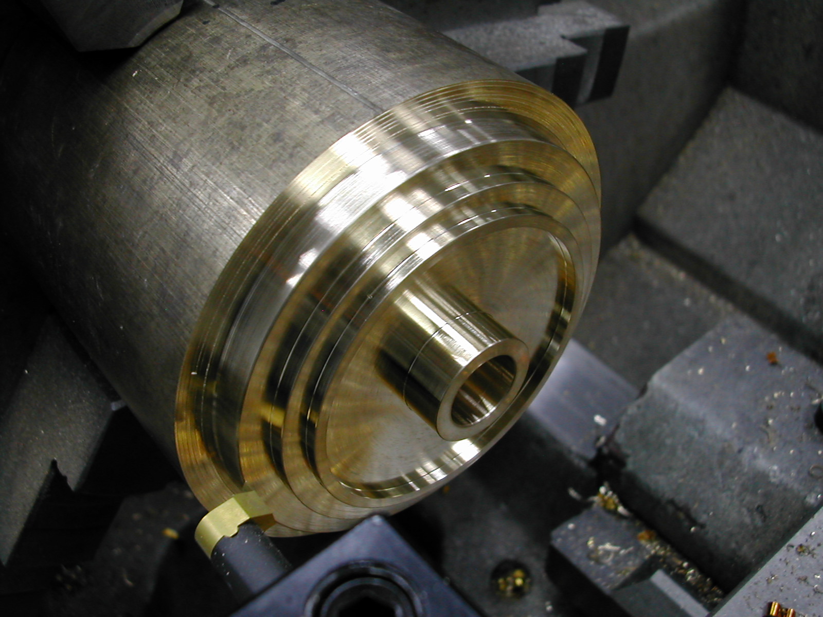
 Next the blank is parted-off from the stock. This is a potential problem area where a lot of heat and warpage can be created. Be sure to use a sharp tool and lots of coolant.
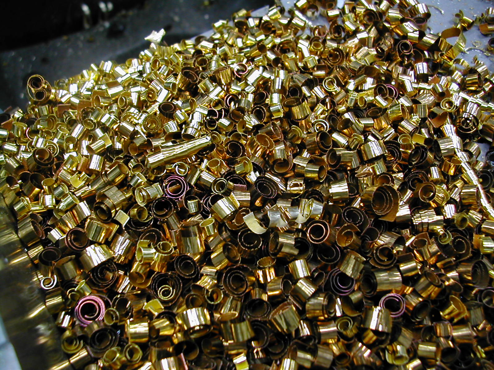 There are almost enough chips here to make another bearing!
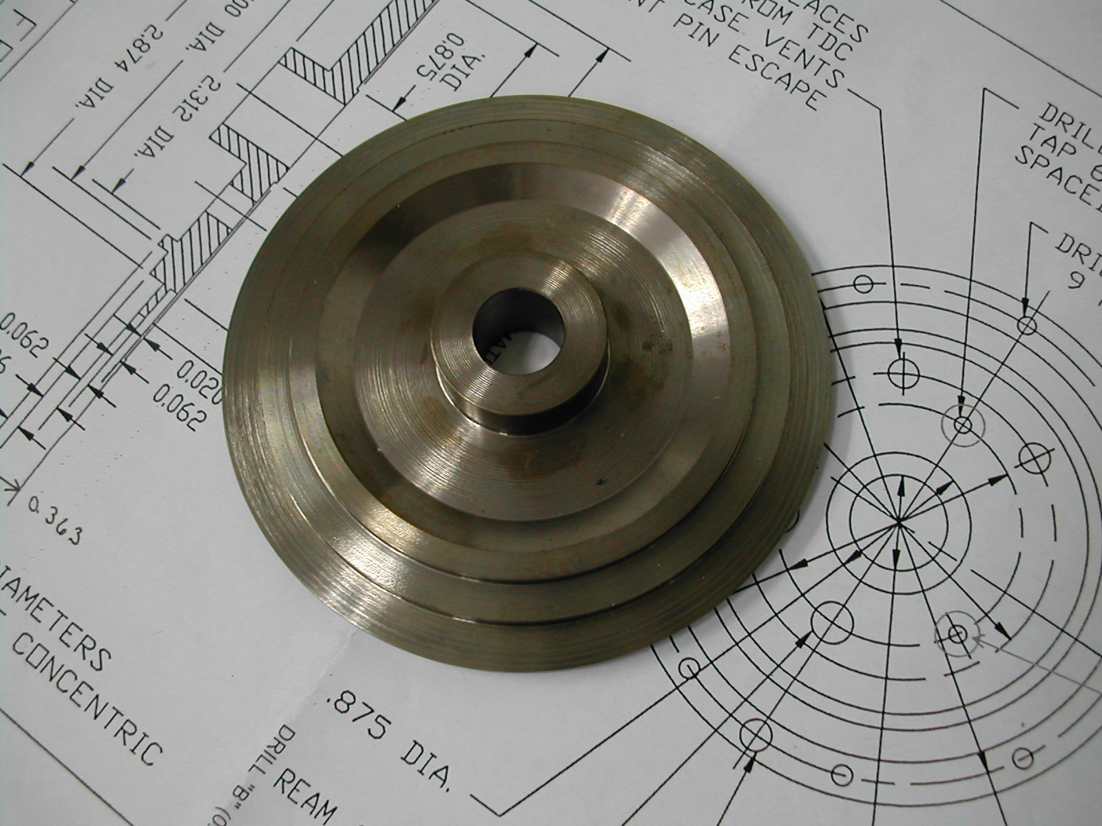 Here is the rough part after 2 hours at 400°C. This stress relieving operation should prevent any warpage of the thin sections during final machining.
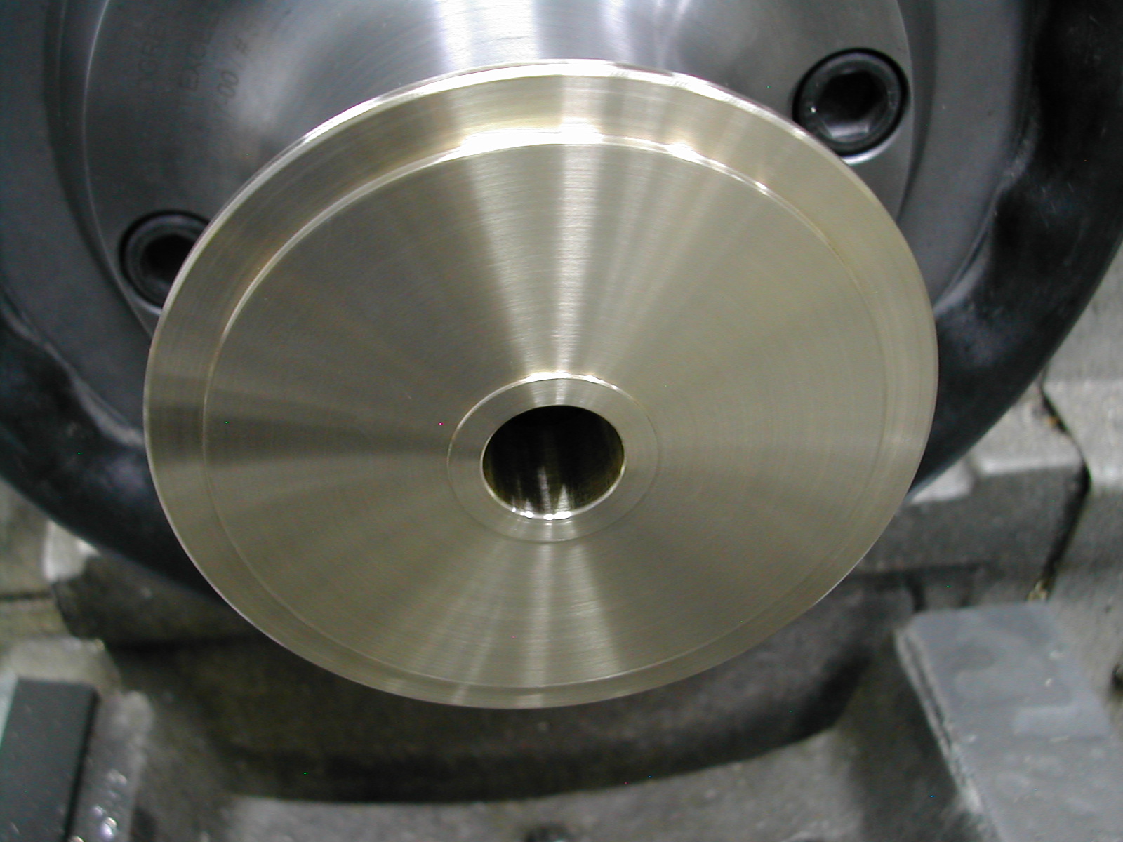 With the 23.5mm boss chucked in a collet, the entire back-side is machined – including the 3.374″ O.D. and the bore. The bore was checked with a 0.594″ and a 0.595″ pin gage. The 0.594″ gage passed and spun freely while the 0.595″ gage did not enter.
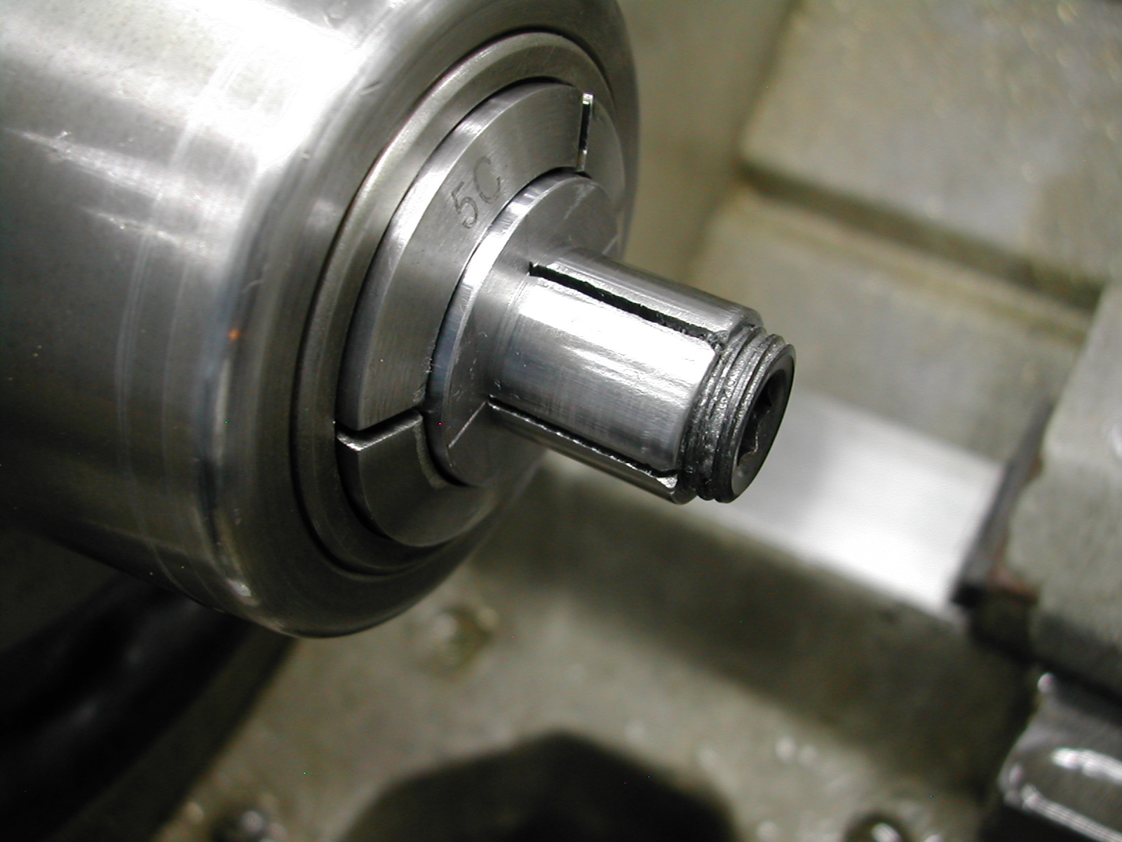 A 0.594″ spud arbor was turned in-situ. This arbor was then tapped for a 1/8″ pipe plug and split with a hacksaw without removing it from the collet.
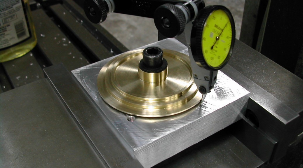
 The part was then mounted on the arbor and the runout of the O.D. and the 0.062″ step previously turned on the backside was checked. Runout in both cases was less than 6µm.
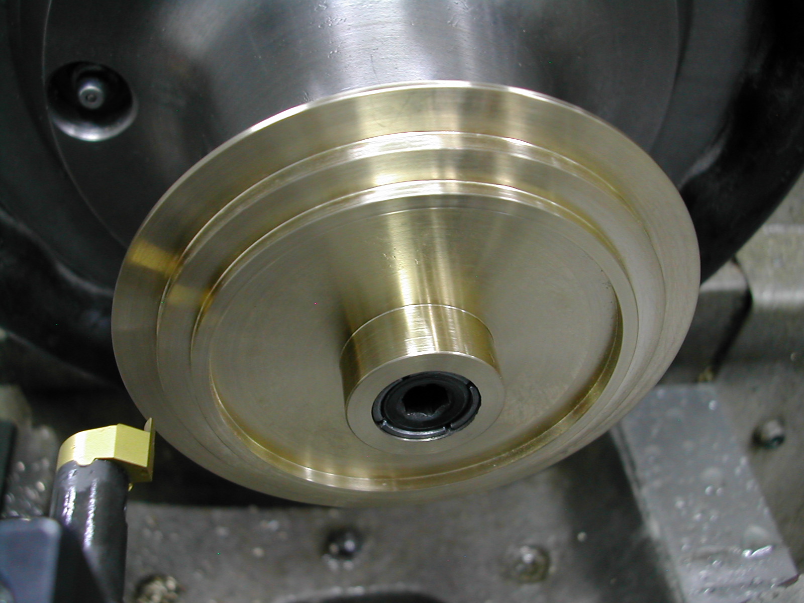
With the part running true, the same face grooving tool as before was used to finish turn the complete face.
Before proceeding on to hole drilling, you should have completed the cam retaining plate and the retaining plate spacers so that the jackshaft holes can be align reamed in both the plate and bearing.
You should also consider completing the turning operations on the rear bearing and oil pump housing so those can be drilled in the same mill setup.
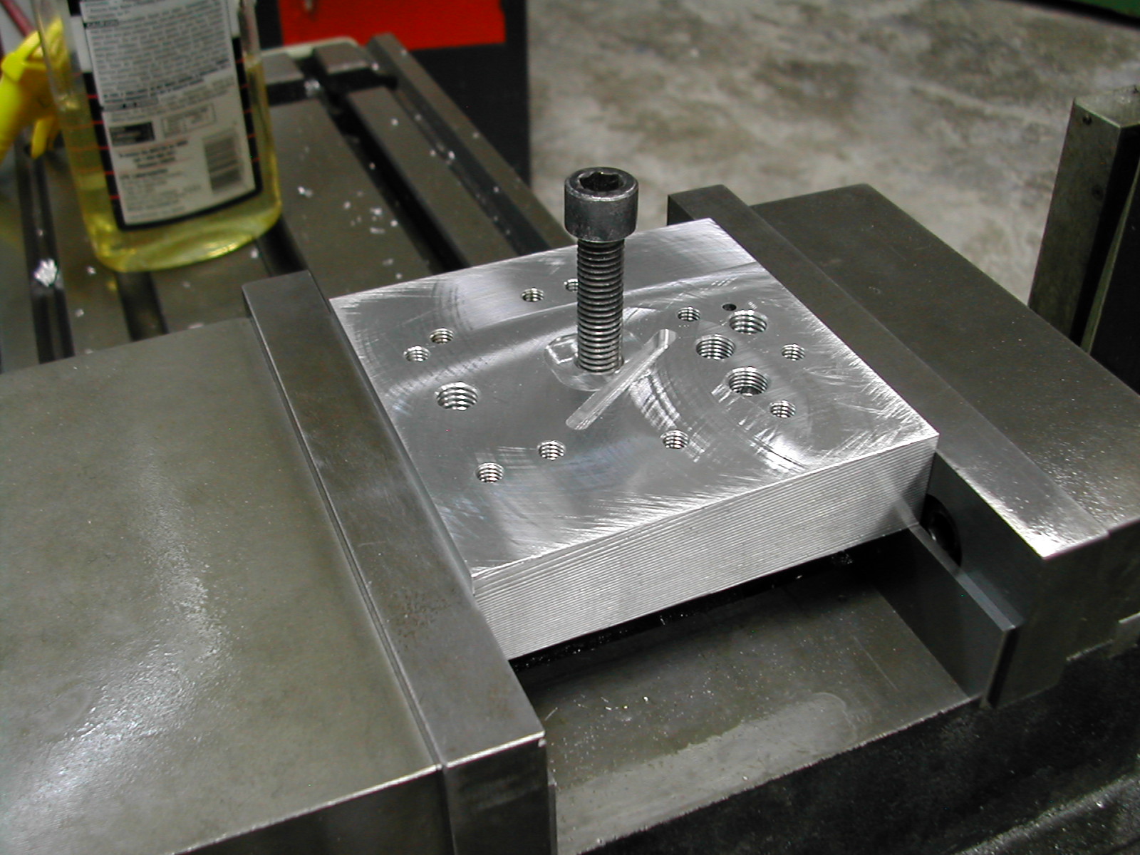 A simple drilling fixture for the bearing was made from a scrap of aluminum. The scrap was faced after clamping in the vise to be sure it was perpendicular to the mill spindle and a M10 hole was tapped near the center.
A 0.020″ recess was milled around the tapped hole to clear the boss on the backside of the bearing so that the majority of the bearing would be in contact with the tooling plate.
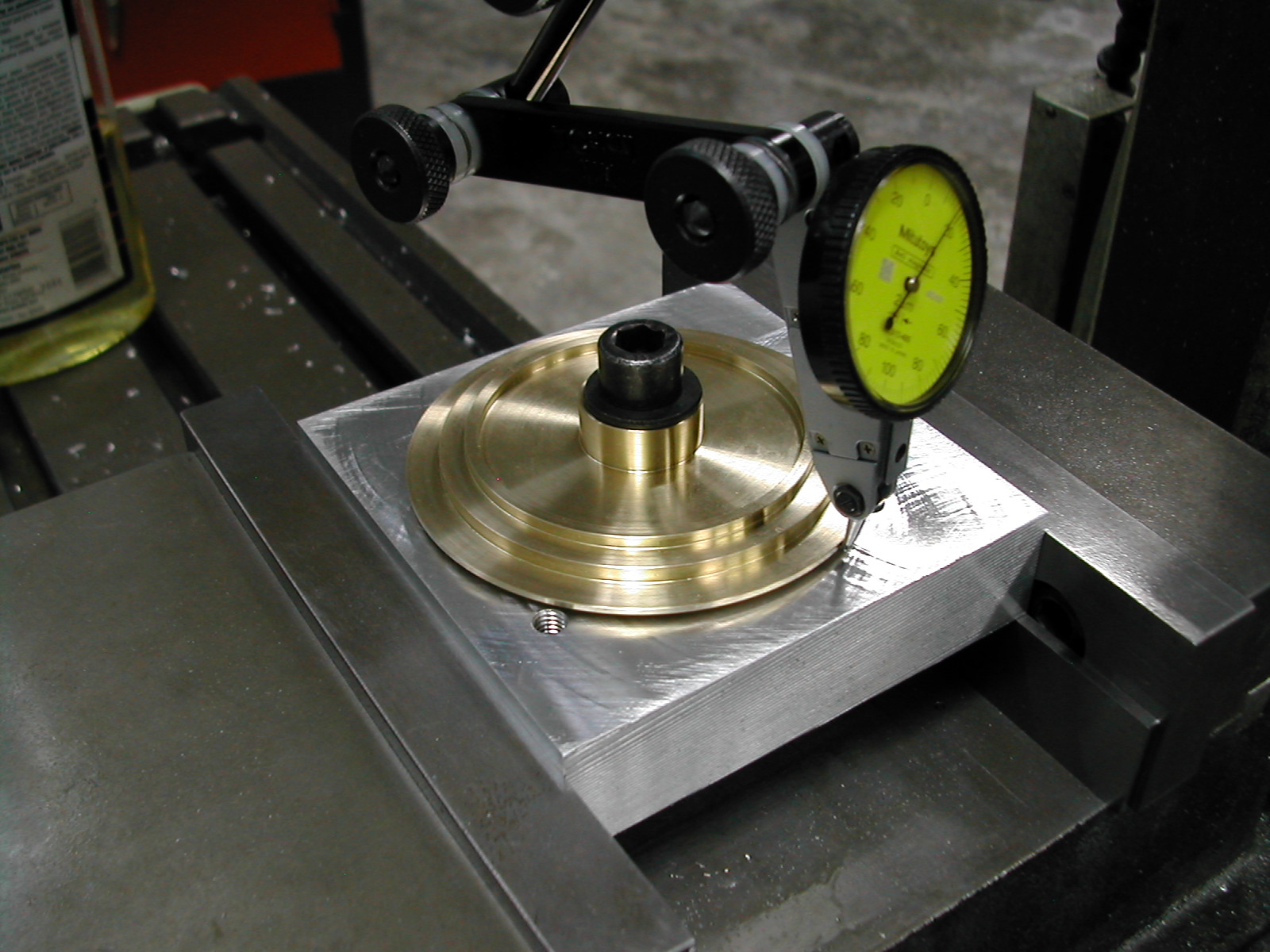 The front bearing was then clamped to the tooling plate with a M10 SHCS and washer. The center of the bearing was then located by indicating the bearing O.D.
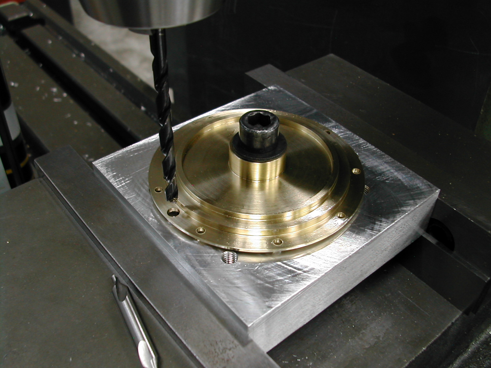 Here the #4 clearance holes around the flange have been drilled and the central oil drain hole at the bottom has been added.
 The two alignment pin escape holes have been drilled and the three #6-32 holes tapped for the cam retaining plate fasteners.
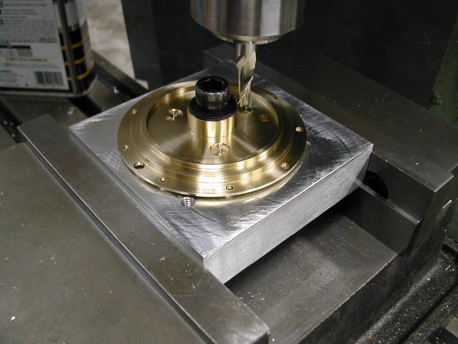 This step is a modification I made to both the front bearing and the cam retaining plate. I don’t like using fastener clearance holes for part locating so I added shallow counterbores to both the bearing and the retaining plate to register the O.D. of the spacers.
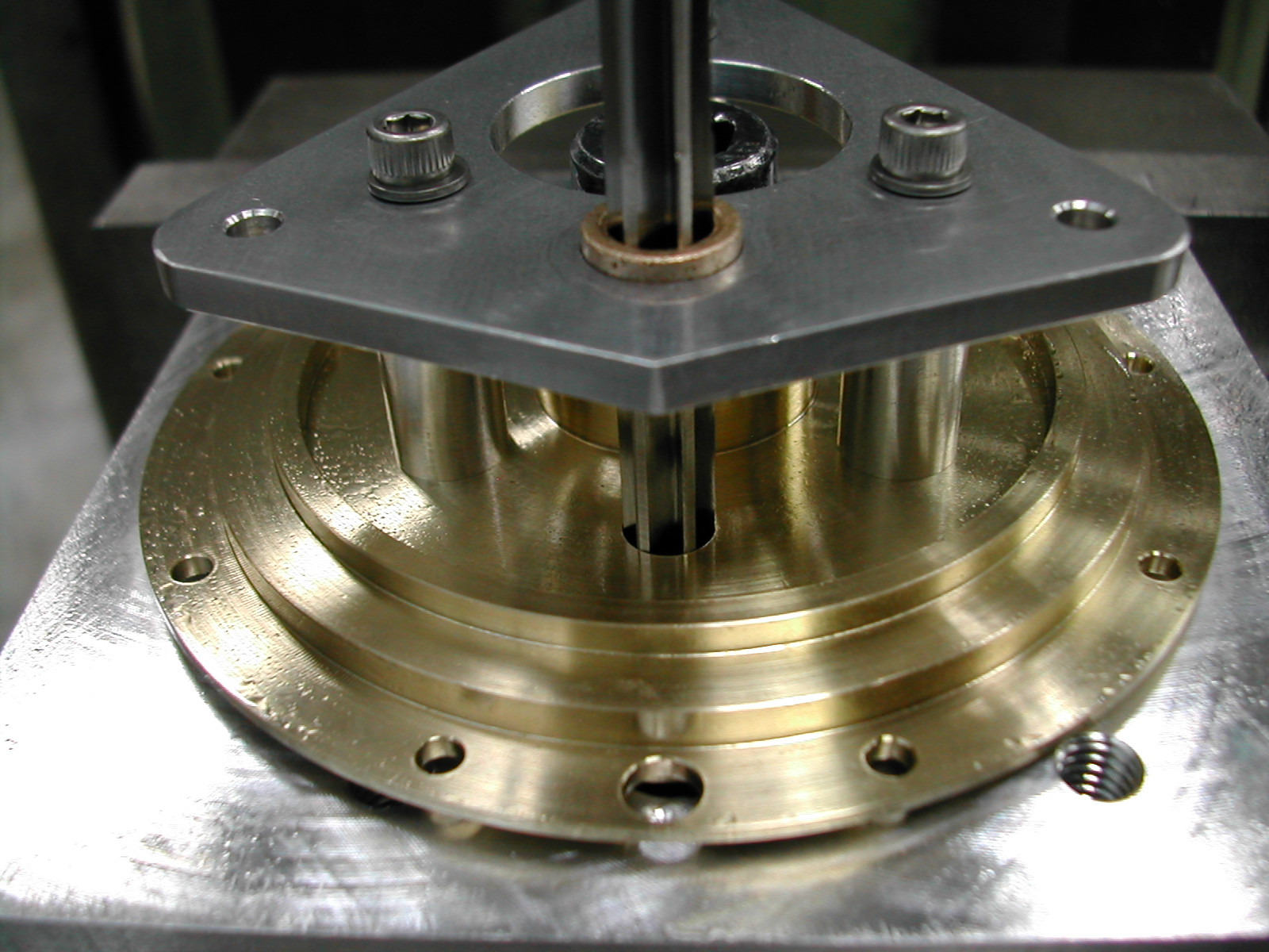
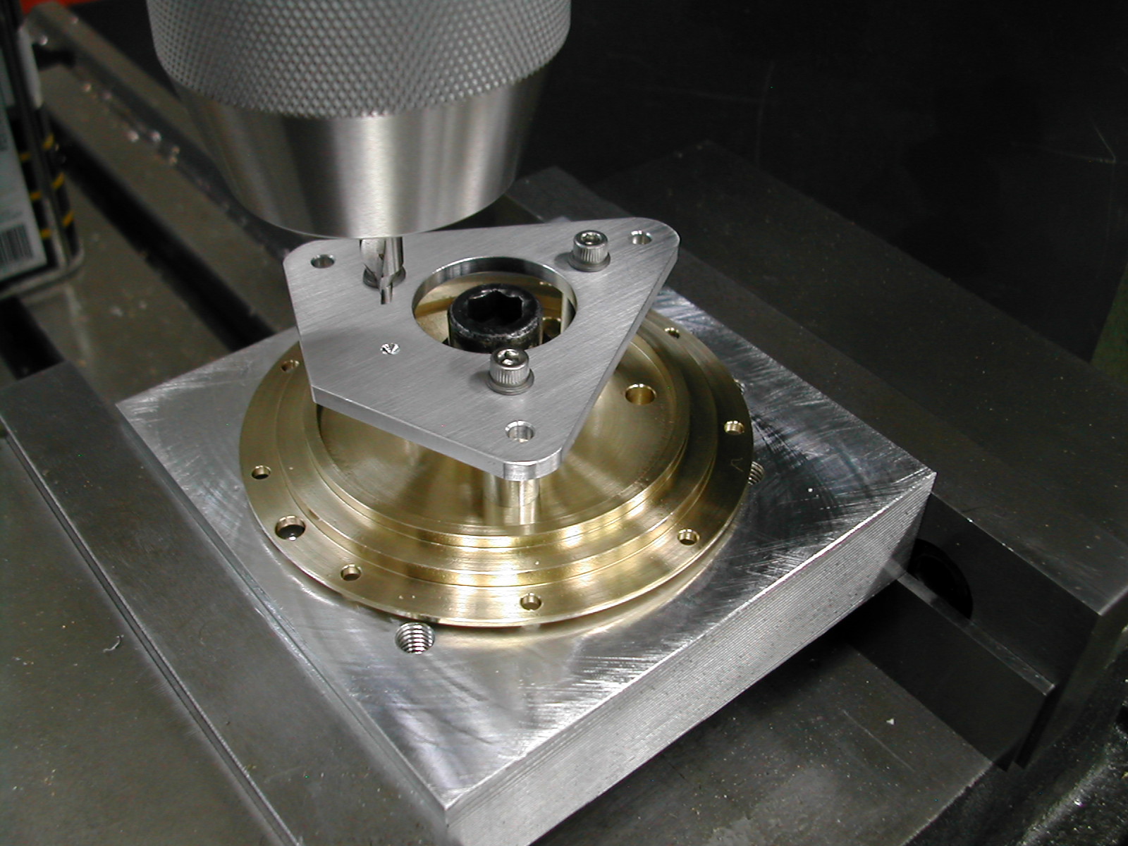 The last hole in the front bearing is the 1/4″ jackshaft hole. The cam retaining plate needs to be attached to the front bearing before this hole can be added. The plate is attached without removing the front bearing from the fixture.
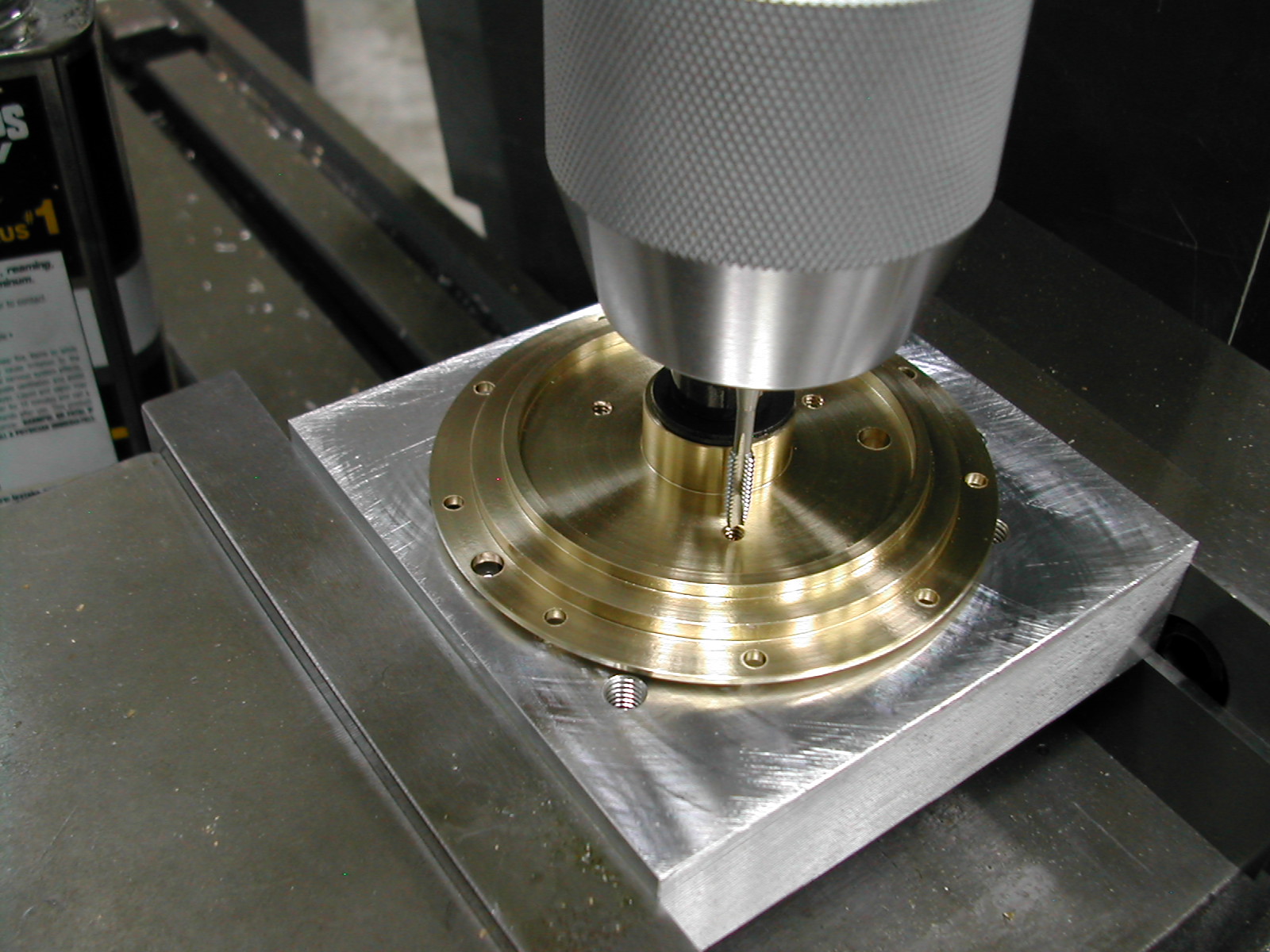
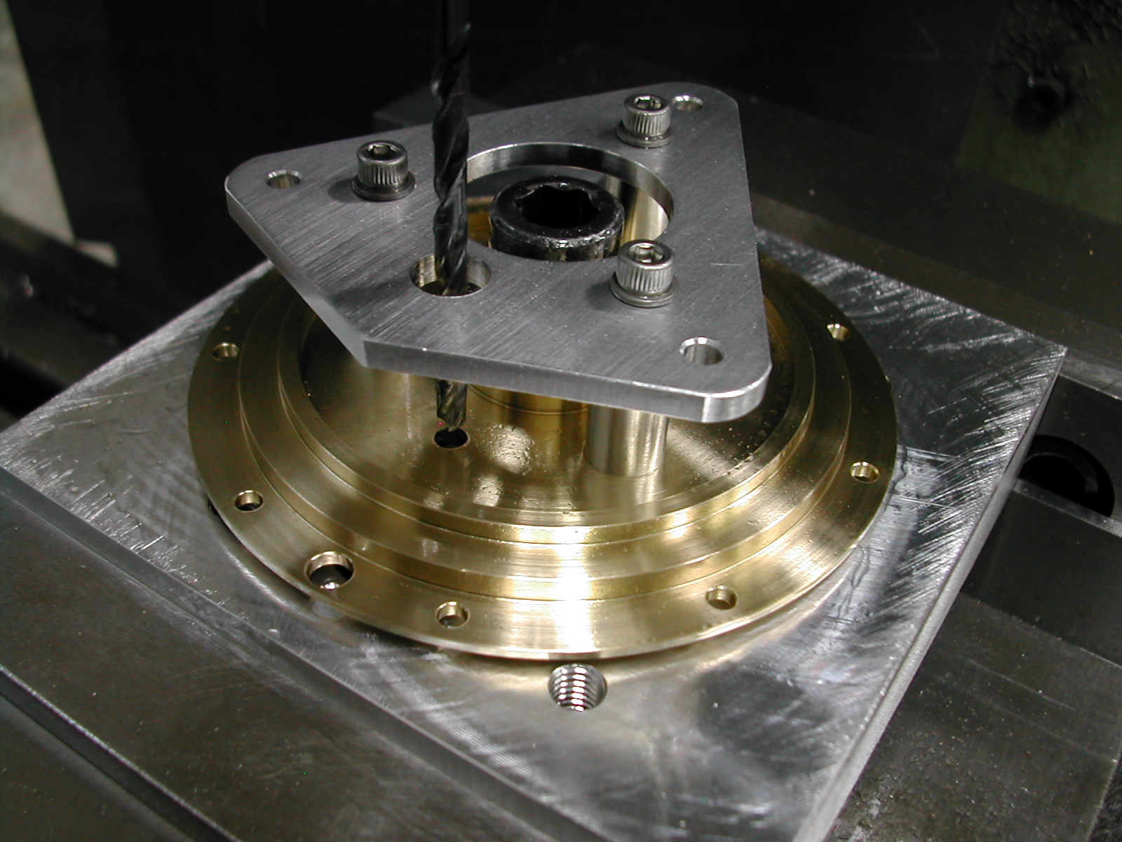 I’ve roughed out the hole for the bronze bushing and now I’m rough drilling the jackshaft hole in the front bearing plate.
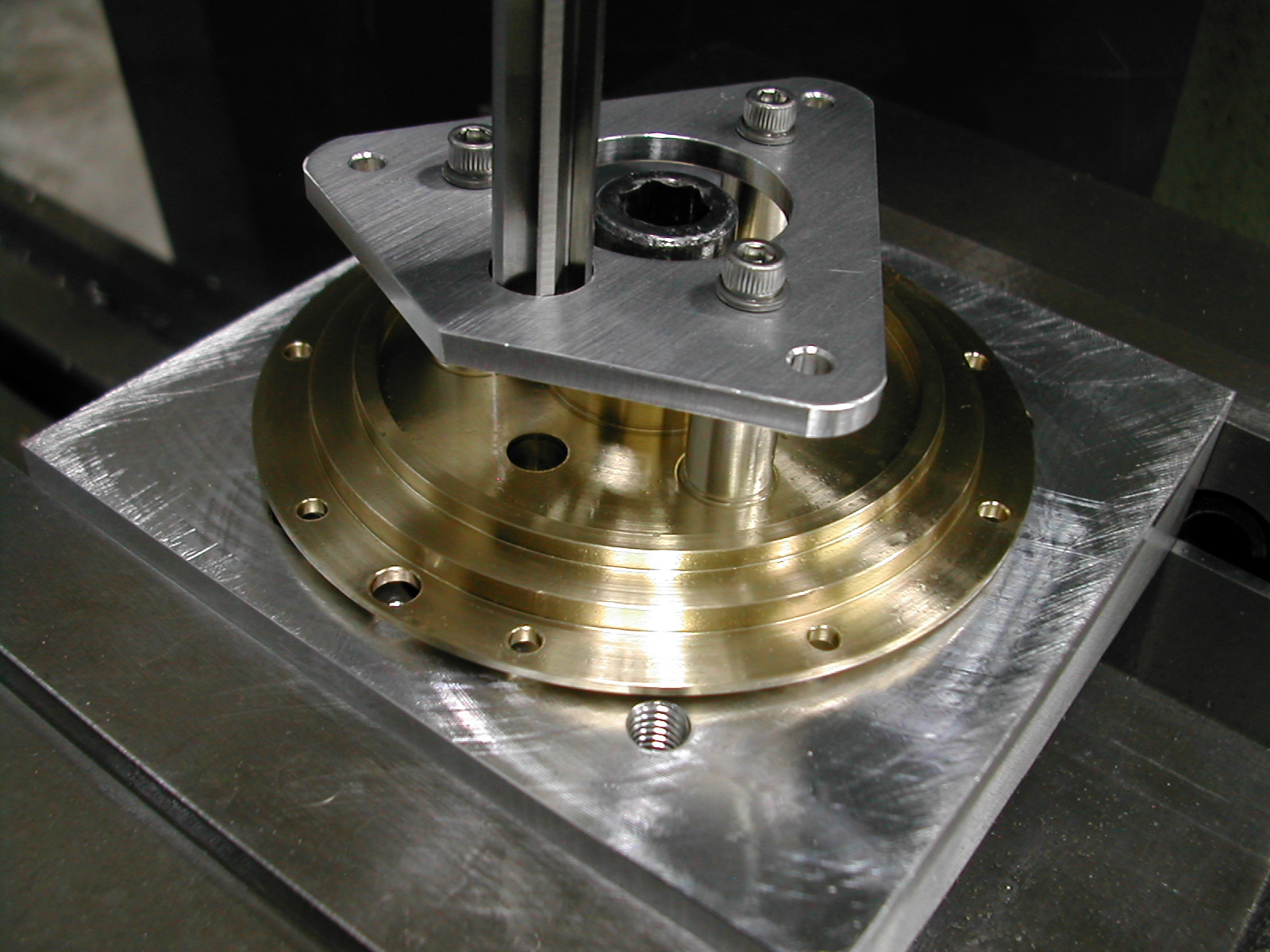 A 0.375″ reamer prepares the cam retainer plate to receive the bronze bushing. The Oilite bushing was a McMaster-Carr part, #6338K411.
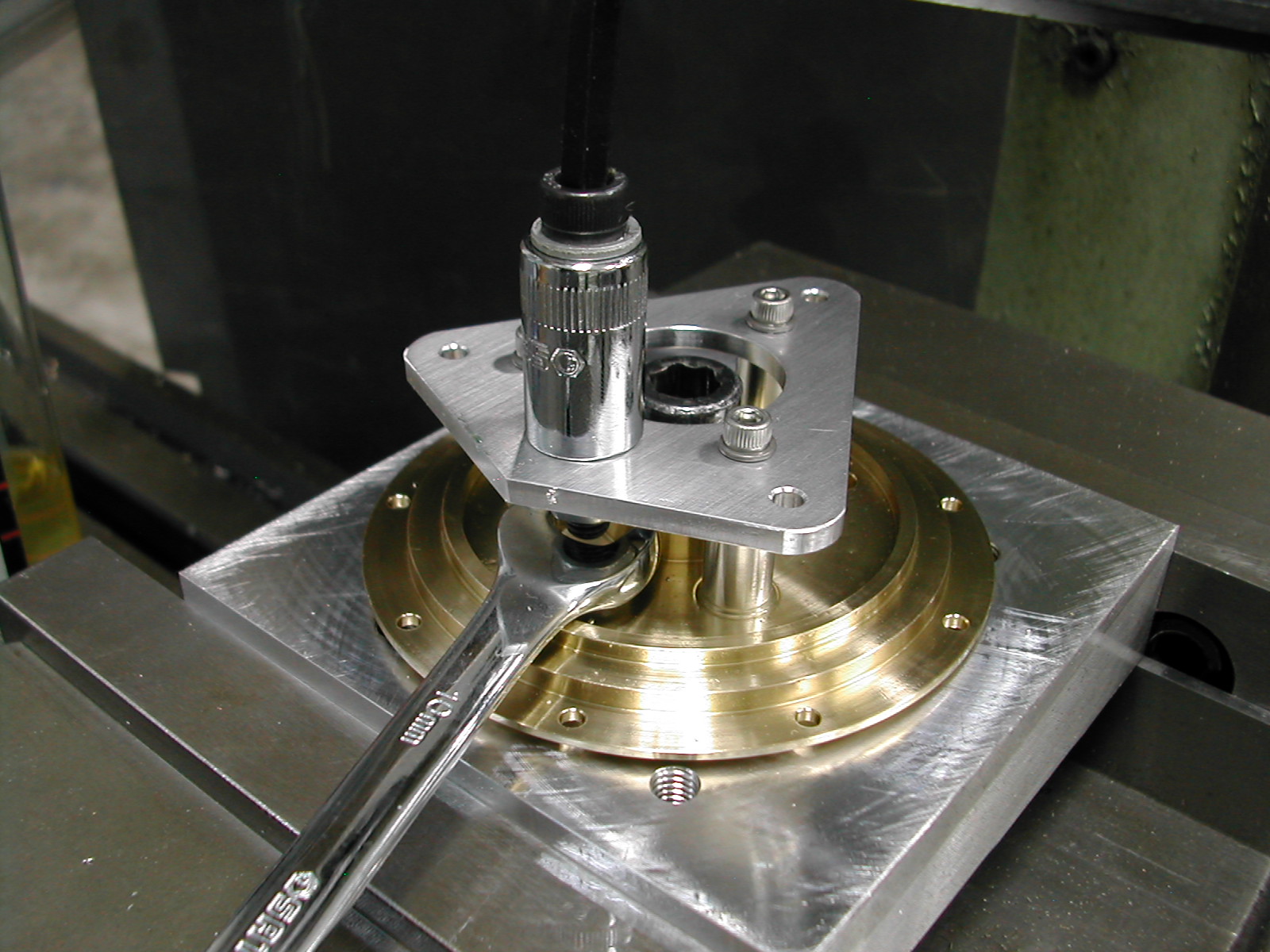 The bushing was coated with Loctite RC680 retaining compound and a draw-bolt was used to pull it into place without removing the plate from the bearing.
 After the Loctite had time to cure, a 0.251″ reamer was run through both the bushing and the front bearing at the same time.
I used a 0.251″ reamer instead of the 0.250″ specified in the plans because I wanted to be sure the bronze bushing cleaned up. I’ll just need to make sure the jackshaft is sized accordingly.
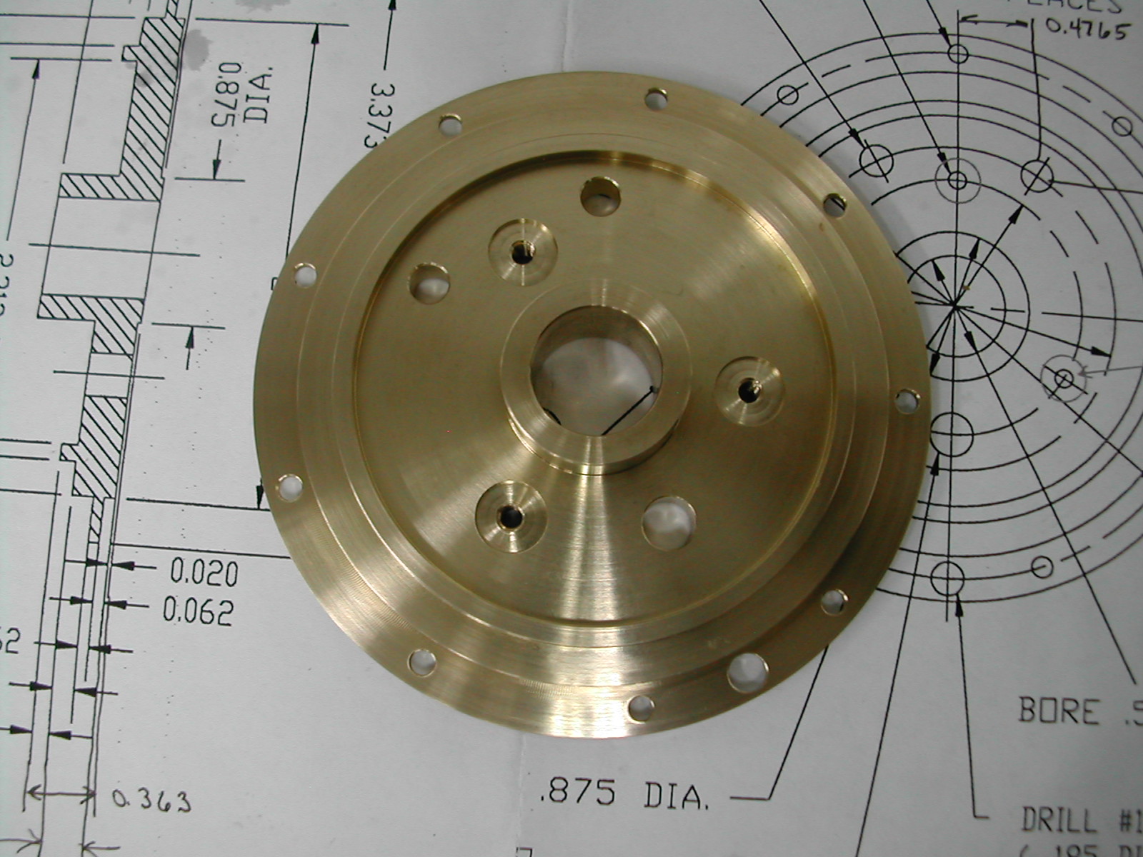
Here’s the completed front bearing.
Disclaimer and License
All material, including the CAD drawings, relating to the construction of the Hodgson Radial presented on this site is free to use any way you see fit. However, no guarantees are made regarding the accuracy or correctness of the material presented here.
Links Used On This Page