
- Hodgson Part 018, Cam Ring
- Hodgson Part 019, Cam Gear & Assembly
 The stock for the cam ring was a piece of heavy-wall 4142 tubing, 3.25″ x 2.0″ in the annealed condition. You can used pre-hardened material, but if you do, you’ll need to anneal it before re-hardening and tempering.
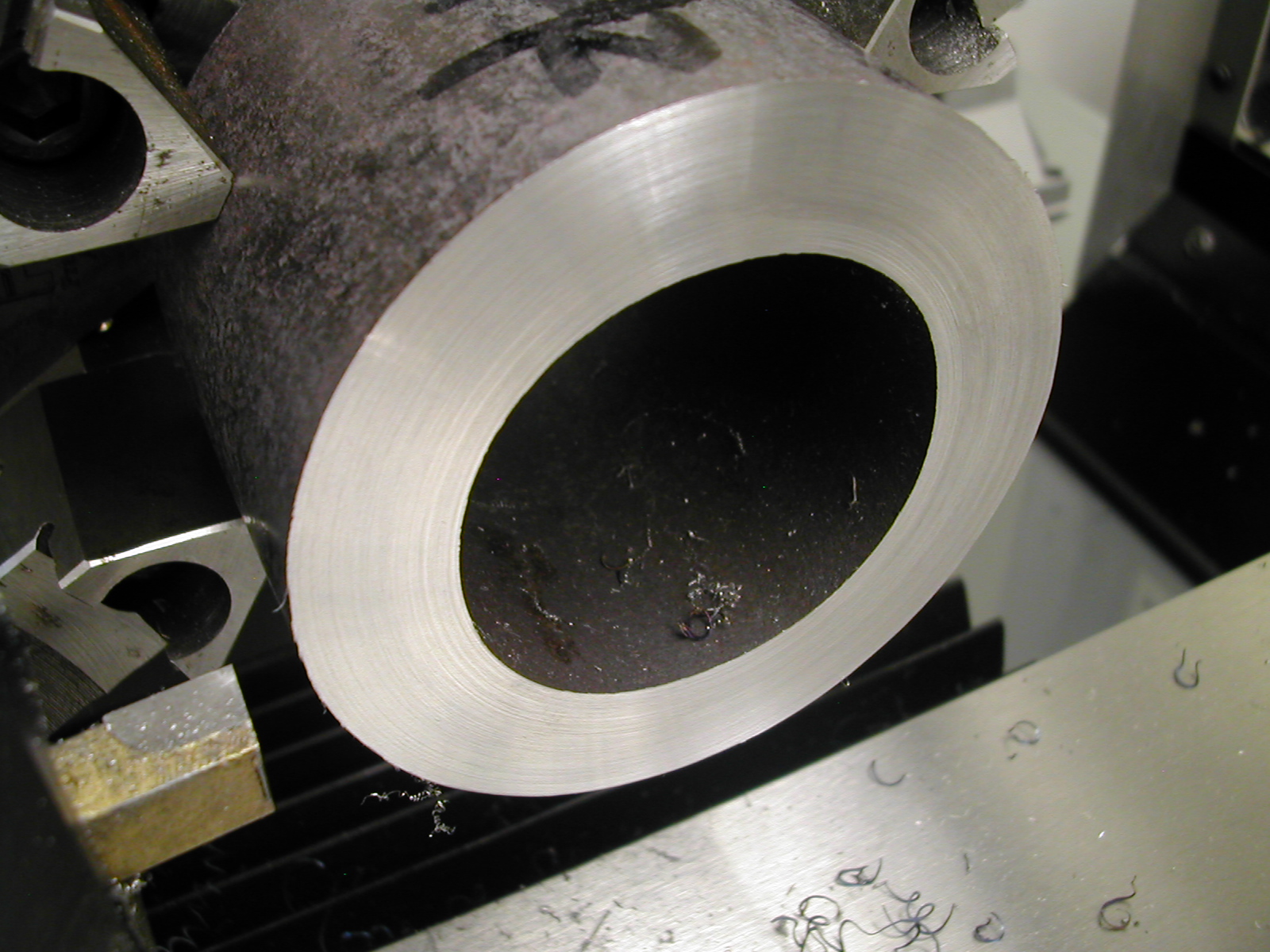
 After facing off the end, the internal work was completed next. First the 2.187″ ID was bored, then the 2.502″ step was turned. It would be good to have already completed your front bearing so that you can check this step for a good running fit on the raised ring of the bearing.
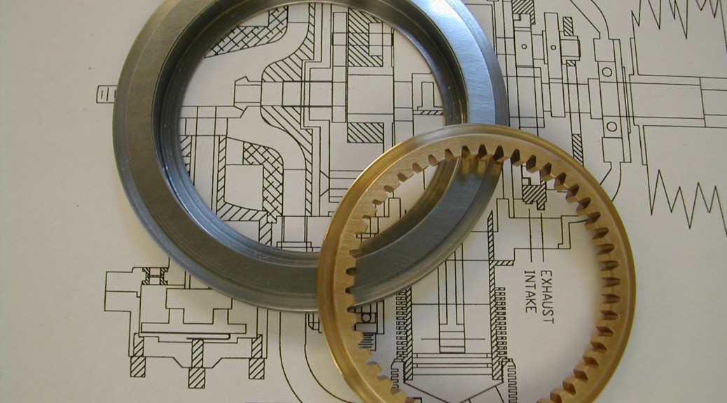
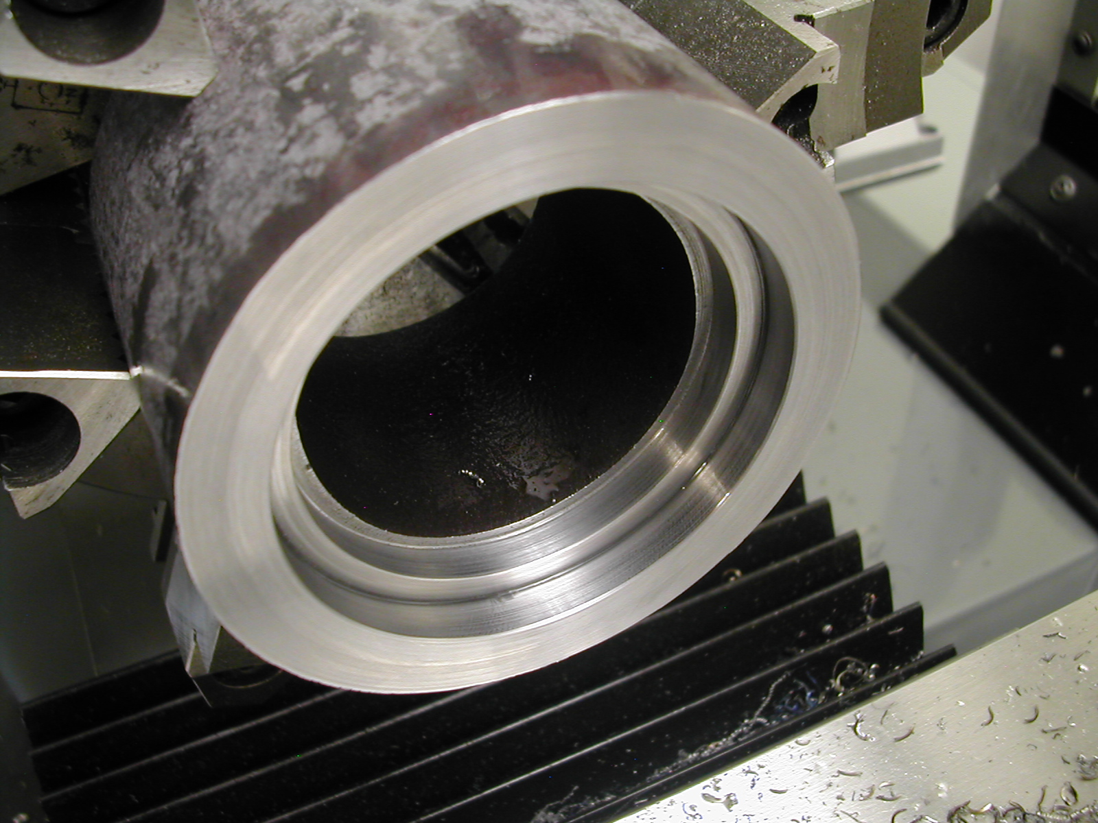
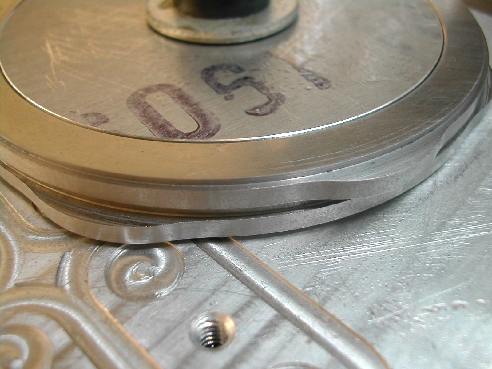
 With the ID work completed, the next step was to turn the OD to 3.175″ and then use a grooving tool to create the intake and exhaust cam rings. Here I’ve switched to a part-off tool and have started separating the cam from the stock. I’ve left the front and back surfaces 0.002″ heavy for lapping to size.
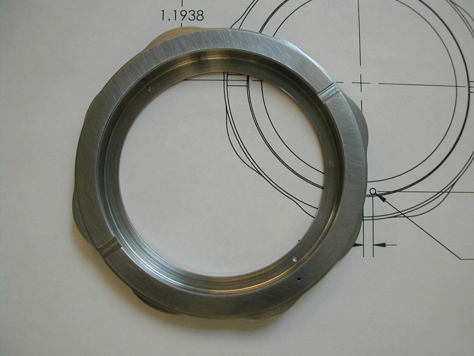
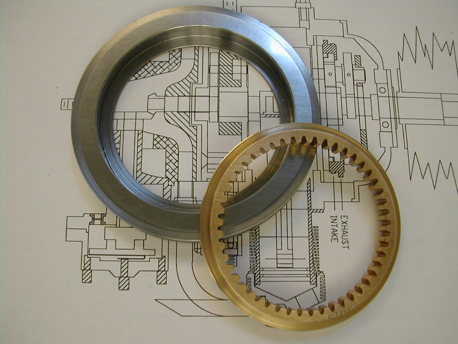 This is the completed cam blank with the front and rear faces lapped. At this point, there is still 0.0005″ excess on the front and back combined for a final lap after nitriding.
I’m going to have my cam Ion Nitrided instead of heat-treated for two reasons: First, nitriding will result in a case hardness around 54Rc with the interior material still soft and ductile, and second with Ion Nitriding, there is no chance of warpage.
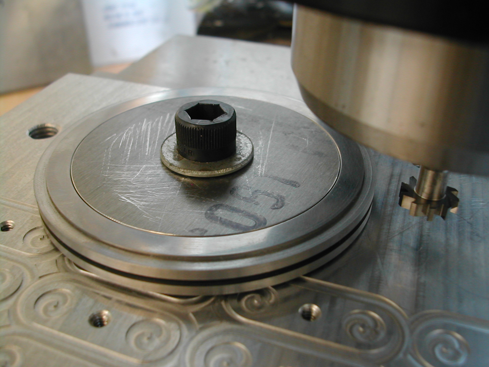
 The mill setup for machining the cam lobes starts with creating an aluminum washer to clamp the cam ring to a tooling plate. Here I have a rough-cut 1/4″ thick piece of aluminum fastened to my tooling plate with a washer spacing it up off the plate so I can machine the OD to 2.501″.
 The cam ring has been clamped to the tooling plate and the center indicated in. A couple of notes here if you are going to CNC machine your cam lobes. First, the diameter tolerance on Woodruff keyseat cutters is +0.010″ to +0.015″ so be sure to measure your cutter. A #404 cutter is not 1/2″ in diameter. It is at least 0.510″ if not more. Second, you’ll get a much better cut surface if you convert the point data provided in the plans into arcs. CamProfiles.pdf contains the converted geometry that I used.
 By converting the geometry to arcs, the cams are machined using arc moves (G03/04) instead of point-to-point linear moves resulting in almost no faceting and therefore no filing and sanding needed on the cam. For what it’s worth, the CNC code I used is available in the donwload links at the end of the page.
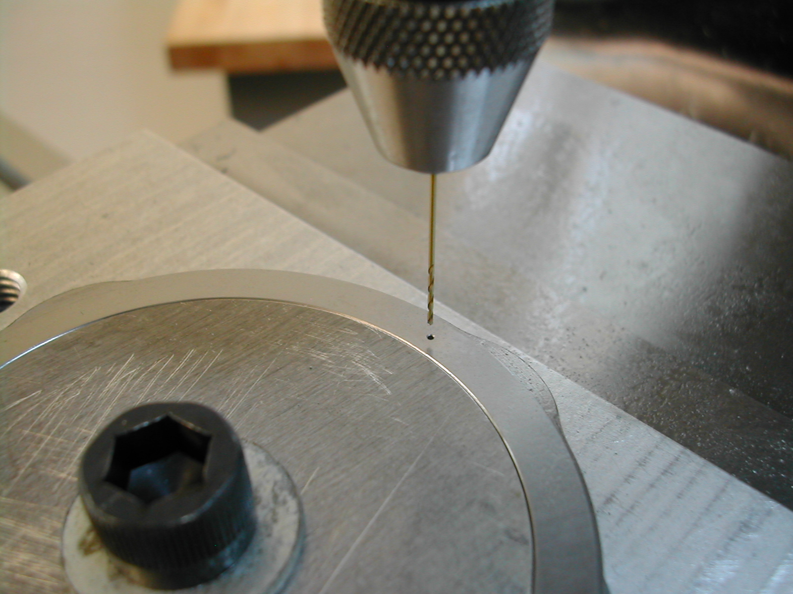 Since I clamped the cam blank to the tooling plate with the front bearing surface up, there was no way to put the 0° witness mark on the back. Instead, I drilled a 0.025″ hole all the way through at TDC.
 Next I added the 1/16 pin holes needed for the cam gear. In my 3D model, I positioned all of the valve train gears in known positions and worked back to the position of the ring gear and determined it should be rotated clockwise 5.1° and centered on a gear tooth. Hopefully this will make timing the cam very easy at assembly.
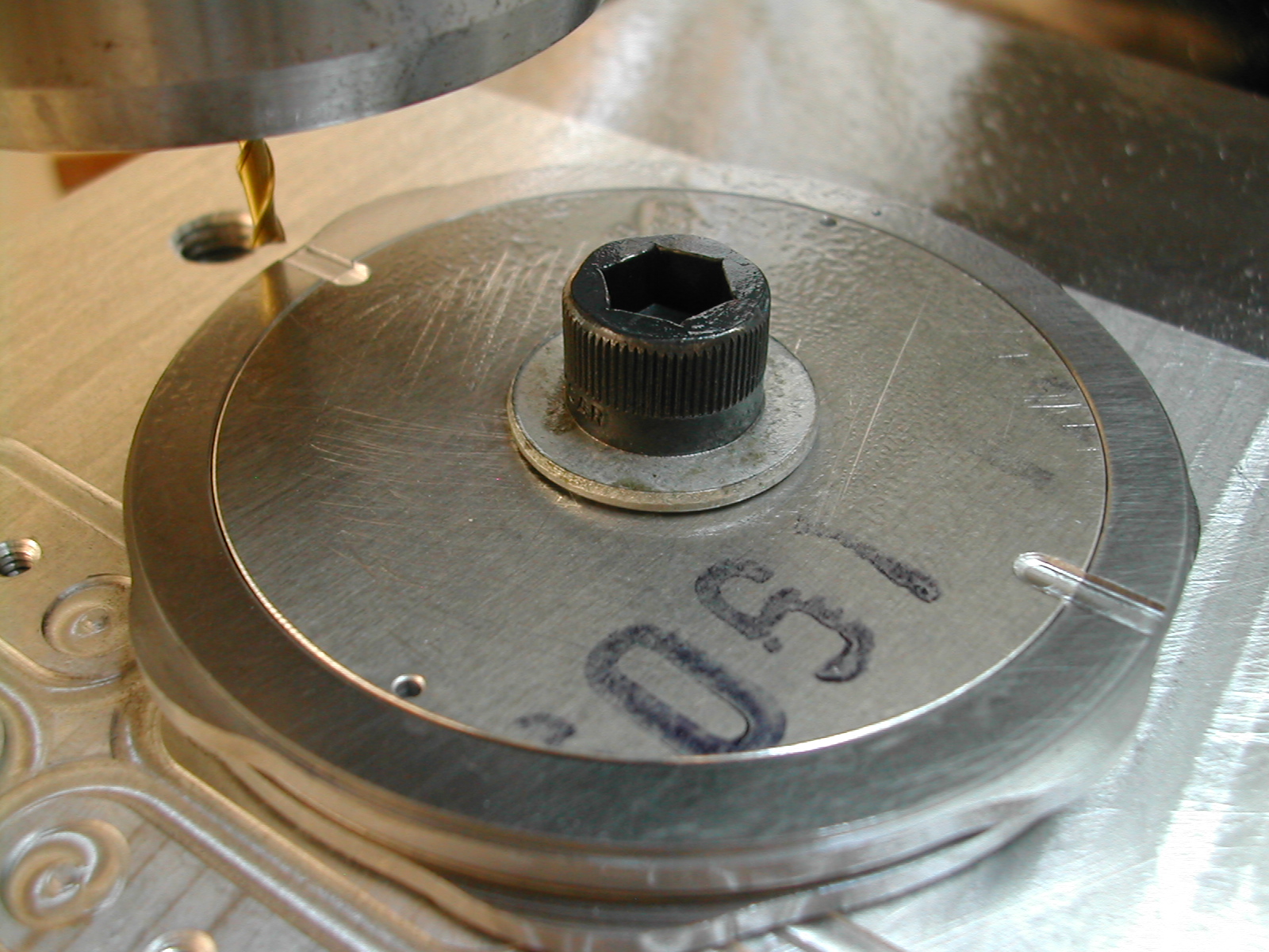 The last part of the mill work was the addition of the 0.015″ deep oil slots.
 The cam ring is now complete and ready for Ion Nitriding.
TO DO
- Nitriding
- Final Lapping
Disclaimer and License
All material, including the CAD drawings, relating to the construction of the Hodgson Radial presented on this site is free to use any way you see fit. However, no guarantees are made regarding the accuracy or correctness of the material presented here.
Links Used On This Page
(CAD drawings are in AutoCAD 2010 Format)