
- Design a Custom AC Timer
- Building the Timer
A fun little project to turn the AC unit on in my office before I get to work in the morning.
Overview
 Here in China there is no central air, so my office is heated/cooled by a room air conditioner. Because of this, it’s cold when I arrive at work in the winter, and hot in the summer, and it takes until about noon for the little room a/c unit to get the room to a remotely comfortable temperature. So an idea was born to create a small, battery powered, IR emitter that would issue the same “ON” command the AC’s remote control does, but does it an hour or so before I get to work in the morning. The end result should be a nice warm office in the winter and a cool one in the summer!
 I originally envisioned this as having an elaborate real time clock and entering the current time and a turn-on time via a serial interface. I finally decided just to turn the unit on at 5:00pm before going home and have it just count 14.5 hours to start up at 7:30am. I’ll have it re-issue the start command every 10 minutes or so between 7:30 and my arrival at 8:30 just in case someone sees the AC running in an unoccupied office and turns the AC unit off.
Discovery
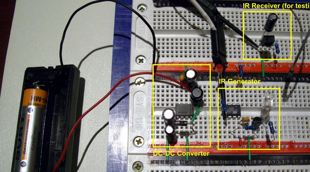
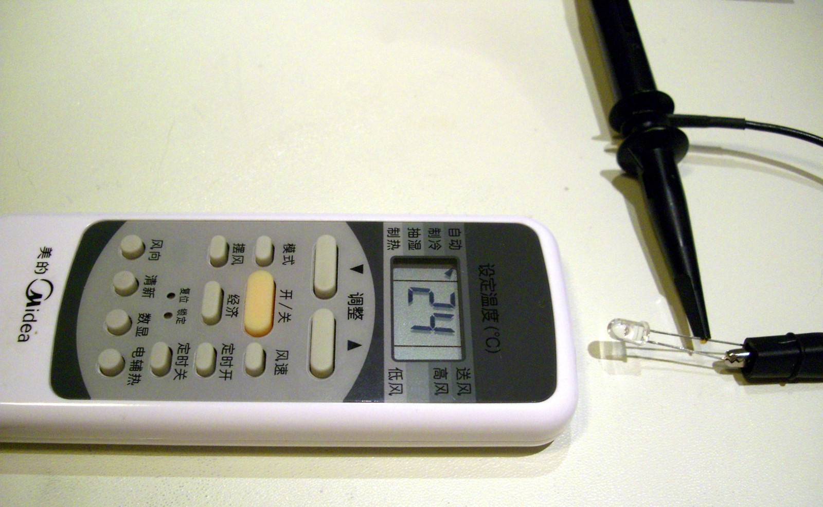
 To determine the carrier frequency of the remote control, I used an IR LED as a photodiode. I hooked the diode up to my oscilloscope and transmitted the start code from the AC remote to determine the pulse timing and carrier frequency.
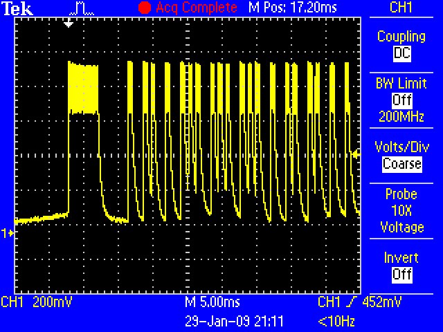
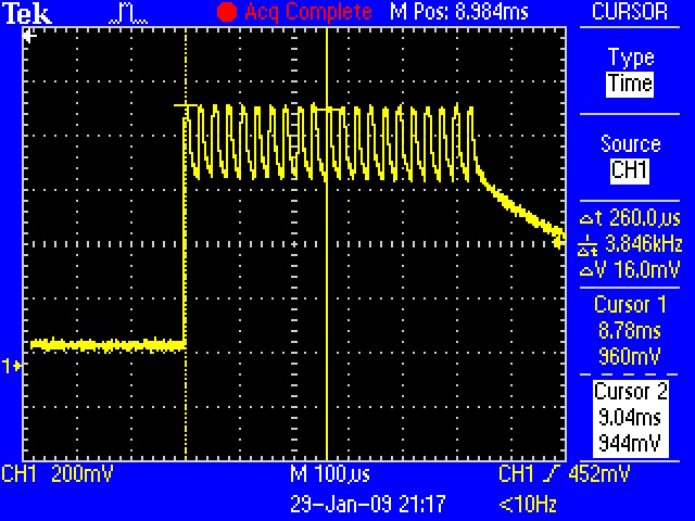 The Midea IR signal uses pulse distance encoding. Each pulse (one “time” unit or 1T) is 21 cycles of a 38KHz carrier burst (about 550µs long). A logic “1” is a 1T pulse followed by a 3T space and takes 2.25ms to transmit. A logic “0” is a 1T pulse followed by a 1T space and takes 1.125ms. The AGC burst consists of a 4.5ms burst followed by 4.5ms space (8T pulse + 8T space). This is very close to the RCA infrared standard.
I then hooked up a IR receiver module of the correct carrier frequency to a logic analyzer to determine the actual data transmitted by pressing the “ON” button. The Midea remote command signal consists of 3 bytes of information.
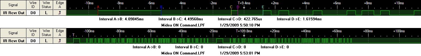 Each byte was first transmitted normal and then inverted for a total of 48 bits of data. This was followed by what appeared to be a single “0” stop bit followed by 4.5ms space (8T). This entire command including the AGC pulse and stop pulse was then immediately transmitted again.
Here’s the Midea remote control output partially deciphered:
 It was observed that Byte 1 appears to be a constant and does not change with any control inputs. The actual determination of what each bit does is left as a exercise for the reader. It was enough for me to just record the code and regurgitate it.
Theory of Operation
Timing will be handled by using the watchdog interrupt. The watchdog will fire every 8 seconds (450 ticks per hour). If we set up a 24 hour counter, then the counter should roll over every 10,800 ticks. If we start our IR emitter at 5:00pm we should initialize the timer counter to 7,650. We want the IR emitter to send the “ON” command to the AC unit at 7:30am (3,375 ticks), then again every 10 minutes (75 ticks) until 8:30am (3,825 ticks).
The internal RC clock is not very accurate. We can minimize the error from this by turning the unit off and back on every day at 5:00pm to reset it. We can also measure the actual length of our 8 second timer tick at the µC/temperature/supply voltage/clock frequency we will operate at and adjust the target tick points accordingly. The IR carrier frequency we generate is also dependent on the internal RC clock so we will also need to measure the actual carrier frequency generated and adjust it as well.
The device needs to transmit one command for heating during the winter, and a different command for cooling during the summer. To keep from having to reprogram the chip for each season, and to minimize the user interface on the device, a simple season select is implemented using the power switch.
Seasons are denoted by the color of the heartbeat LED. Red for winter (heating mode) and green for Summer (cooling). If the device is switched off during the first 8 seconds, it will start back up in the next “season”. If the startup season is correct and the device is allowed to run longer than 8 seconds, then the next startup will be the same as the current season.
Season information is stored in non-volatile EEPROM. Assuming the device is started twice per day (worst case when changing seasons), then four EEPROM writes occur per day. With a life of 100,000 write/erase cycles, that gives us a 70 year life span for the EEPROM memory.
Season mode changing is a little tricky because of sleeping in power-down mode. The processor is using very little power so there is enough power stored in the filter capacitors to execute a few cycles after waking even if the power was switched off long ago. Therefore, when changing modes, be sure to leave the power off at least 8 seconds (1 timer tick). That way, the processor will awaken and then attempt to flash the heartbeat LED effectively draining the stored energy, and preventing the mode toggle from executing unexpectedly. Be sure to enable Brown Out Detection in the fuses to get reliable shutdowns.
Much more in the source code comments!
Applicability
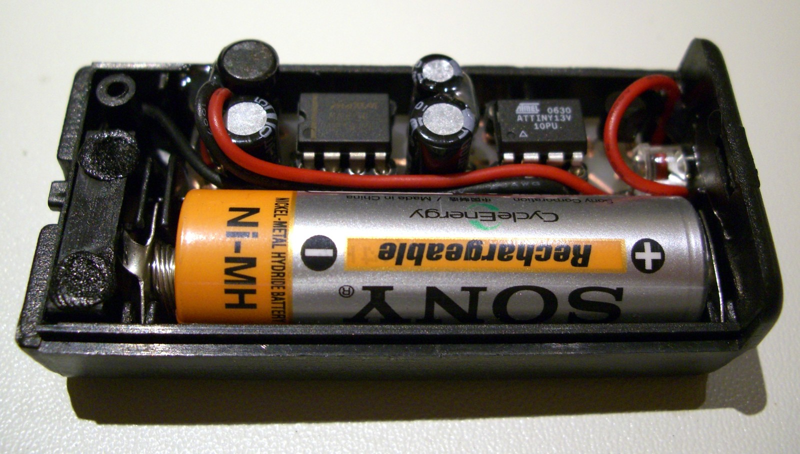
Unless you have a Midea air conditioner in your office, this project will probably not help you very much. However, there are a few building blocks here that can be re-purposed to do many useful things. The DC-DC voltage converter can be used to drive many 3.3V or 5V low power devices from a single 1.2V rechargeable AA cell. The packaging in a 2-AA cell battery case might give you some ideas for your own projects. The ATTiny13 controlled IR emitter circuit might be used to control many other IR devices, and the well-commented source code is a great learning tool in and of itself.
Next post: Building the unit.