
- Design a Custom AC Timer
- Building the Timer
 Here I finish up my project to turn the AC unit on in my office before I get to work in the morning by building the timer unit.
The Finished Product
Project Sources
Construction
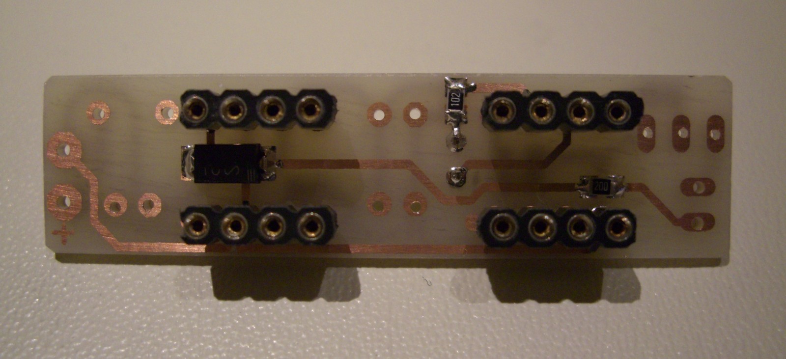
The circuit consists of two parts; the DC-DC converter and the IR signal generator and emitter. The Maxim MAX756 DC-DC Converter is supplied with a single AA battery. You can use either a 1.2V rechargeable, or a regular 1.5V Alkaline cell. The ‘756 converts this to 3.3V to supply the Atmel ATTiny13A which handles the control logic and signal generation.
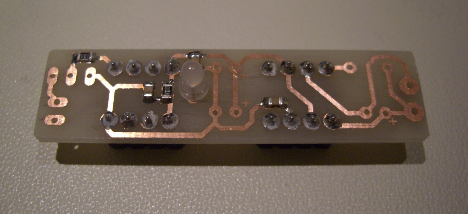
 The µController portion is very simple. A bypass cap and weak pullup are attached to the chip reset line to prevent inadvertent resets from occurring. The IR LED operates at 100ma – too high to run directly from one of the Tiny’s output pins, so we use a common 2N2222 transistor to buffer the current. The “heartbeat” LED is a 3mm bi-color 2-lead red/green LED. If we pull I/O pin PB1 low, and set PB2 high, we get green light. Pulling PB2 low and setting PB1 high generates red light. That’s it for the hardware, other than a two cell AA battery case with an integral on-off switch which we house everything in.
The circuit was breadboarded to work out the bugs and create the software before the layout and creation of a printed circuit board. You could probably wire this up “dead-bug” point-to-point style, but as easy as PCBs are to create using the toner-transfer method, it almost as fast and far more professional just to go ahead and make one.
It’s a little bit more trouble to make a double-sided PCB using toner-transfer, but certainly doable. Briefly, here’s how: Clean one side of the board, iron on the image. Apply clear packing tape to the other side to protect it in the etch tank and go ahead and etch the first side. After etching, remove the packing tape then pre-drill two of the holes in the board slightly larger than a straight pin. Clean the other side of the board, and using pins to align the artwork, iron-on the second side. Apply tape to cover the already etched first side, and then etch the second side. Remove the tape after etching, then drill and trim the board.

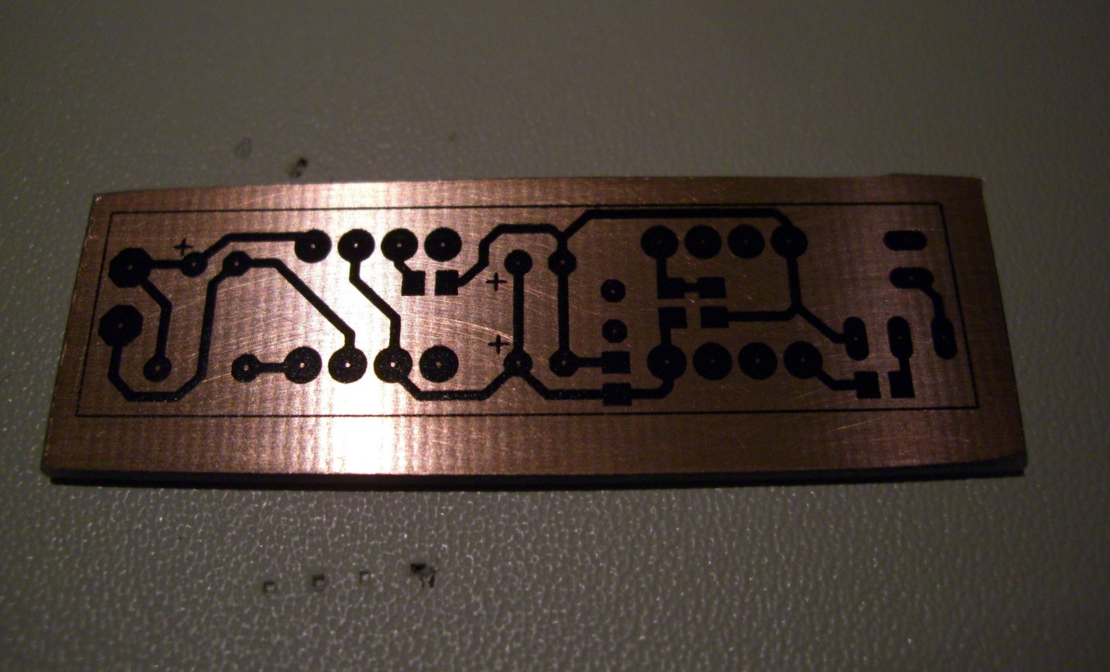

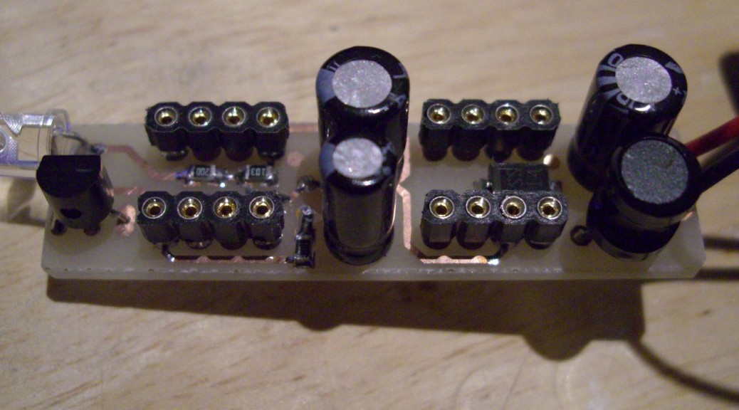
Laying out a double-sided board for making at home is a little more involved since you don’t have plated-through holes. It helps to use a mixture of through-hole and SMD components to reduce the number of vias required. You also need to remember that not all through-hole components can be soldered on both sides (i.e. electrolytic caps, LEDs, etc.). I decided to socket the µC and DC-DC converter so it would be easy to salvage the chips later. I like to use turned pin sockets for this since both sides can be easily soldered. Using these techniques, this board was made without any vias.

Start by installing the lowest components first, usually the SMD devices. Then work your way up to the tallest items. Think about what needs to be soldered on each part, especially on the top of the board, to make sure you don’t put something in the way of soldering a connection later. I like to clean the flux of the board a couple of times as I go since the top gets pretty hard to clean as the taller components start going on.
The Finished Product
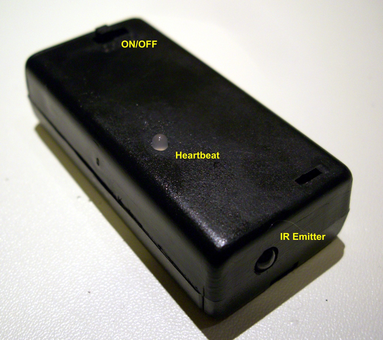 And here’s the completed device. Before I leave work for the day, I switch it on, make sure it’s in the right mode, and set it on my desk pointing at the AC unit. Next morning I arrive to a wonderfully comfortable office!
Disclaimer and License
It worked for me so it should work for you, but no guarantees. Feel free to use the schematics and information on this page as you see fit, but a little attribution would be appreciated.
Project Sources
- AVR Studio GCC Source (25K .zip)
- Cadsoft Eagle Files (71K .zip)