
- Ball Turner Design
- Ball Turner Manufacture
Starting Work in the Shop
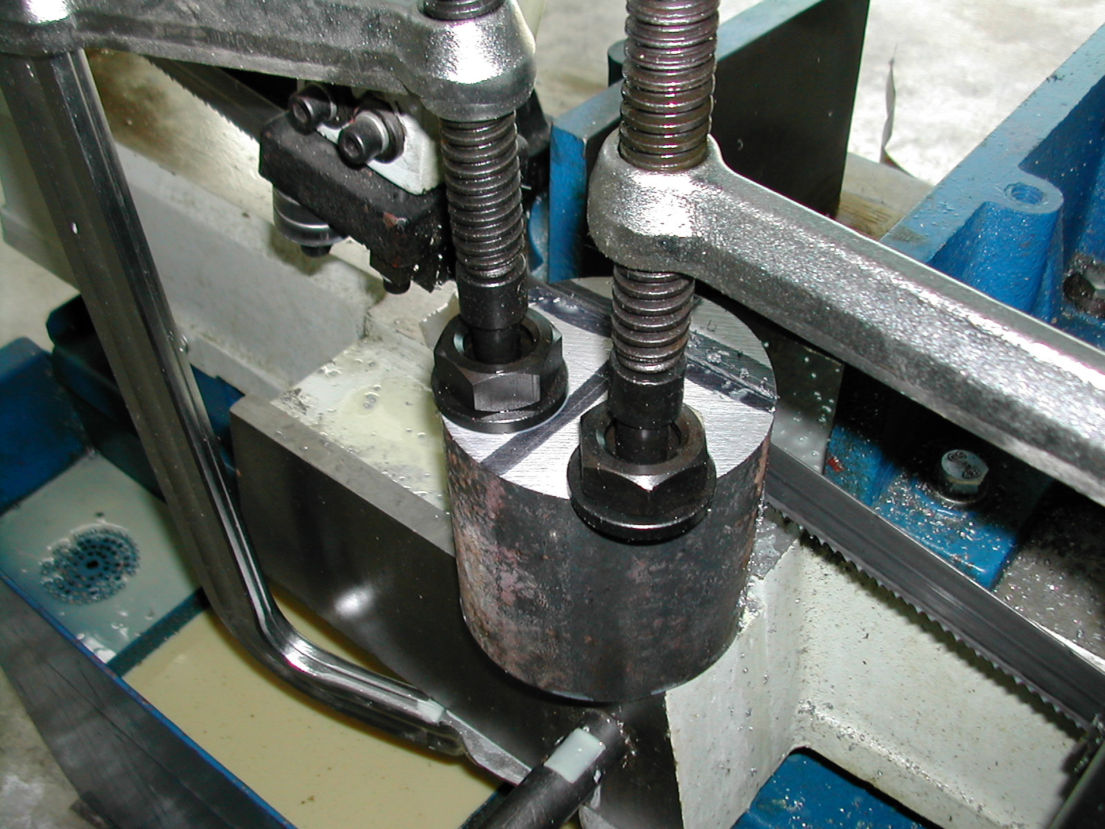 The first stop in the machine shop for all projects is cutting the stock. Here I’m squaring up a piece of hot-rolled mild-steel round stock in the band saw to make the ball turner body. The cant being removed in this photo will be further sawn to make the rotation stops.
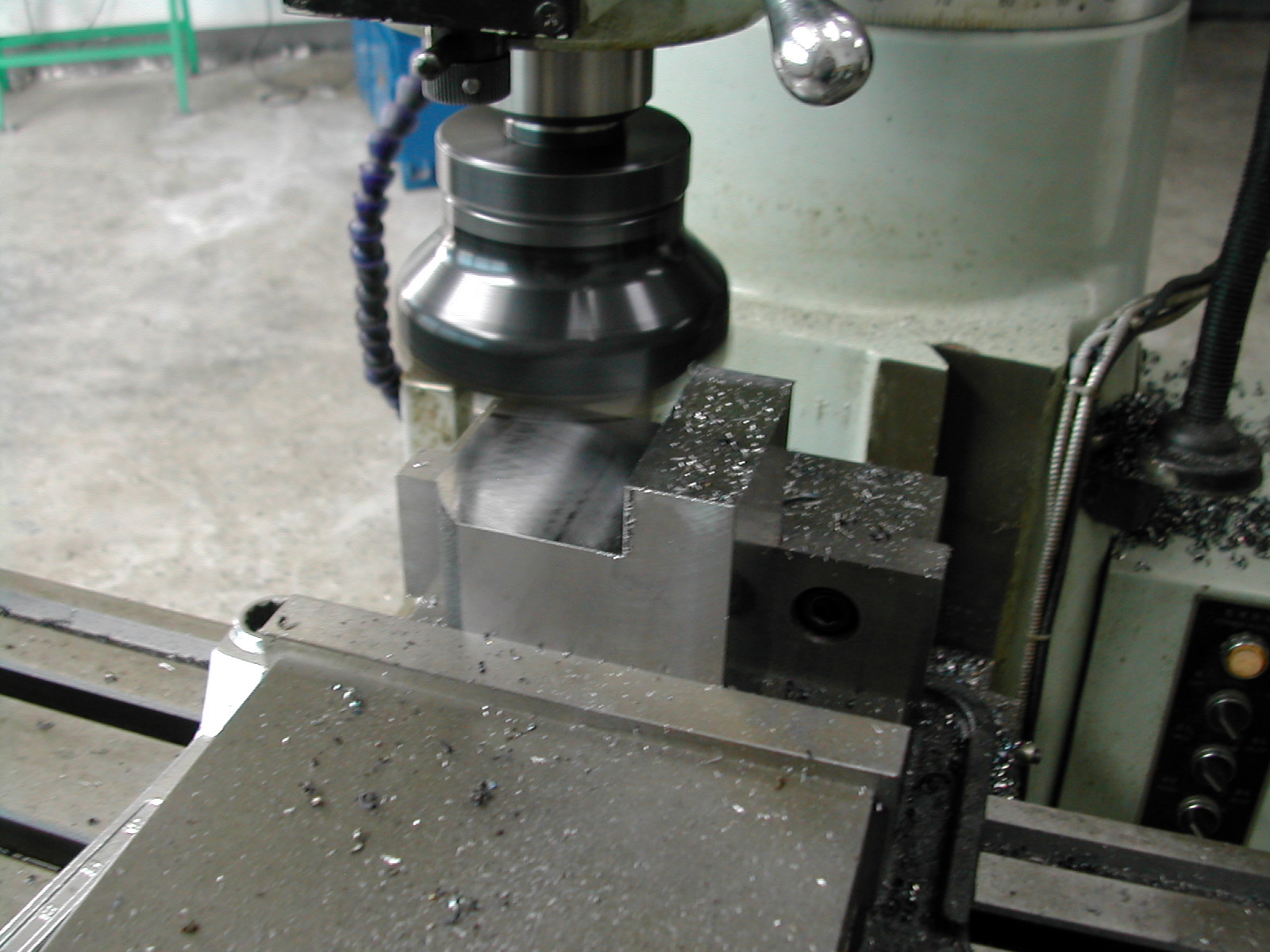 Once everything is rough sawn, we start on the mill squaring everything up and milling it to finish size. Here, I’m using a nice insert face mill to rough out the recess for the boring head.
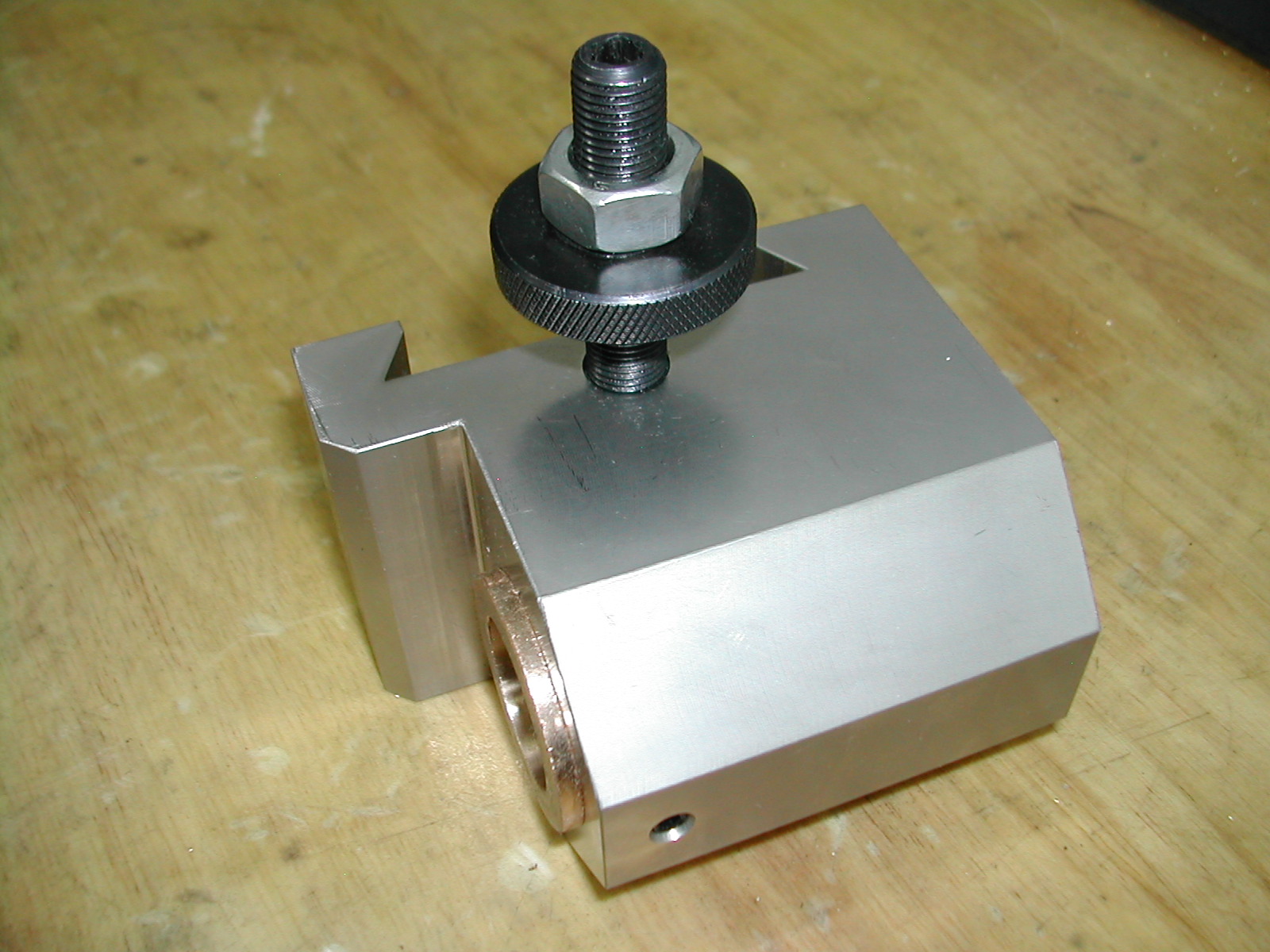
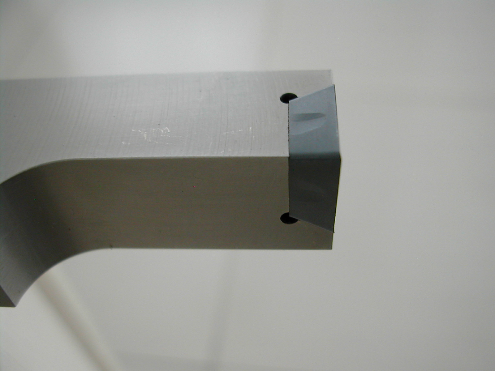
 The body is finished. The bushing bore is finished, excess weight has been knocked off the unneeded corners, and it’s been drilled and tapped for the height adjusting screw. You can just see the stop pin hole on the lower left.
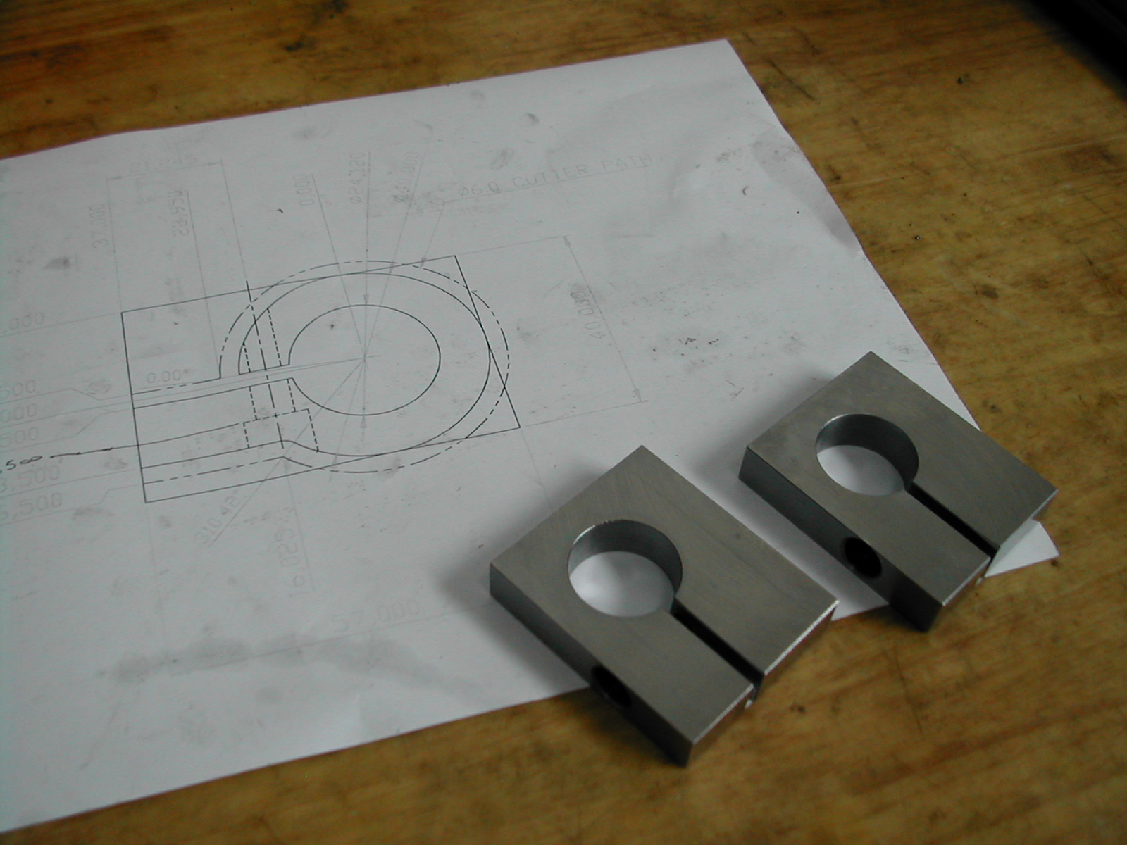 Here the two stops have been squared up out of the cut-off from the body stock. I’ve bored them, drilled and tapped the clamp screw hole, and slit them with a slitting saw. the detail print they are sitting on is one of the layers in the 3D model drawing.
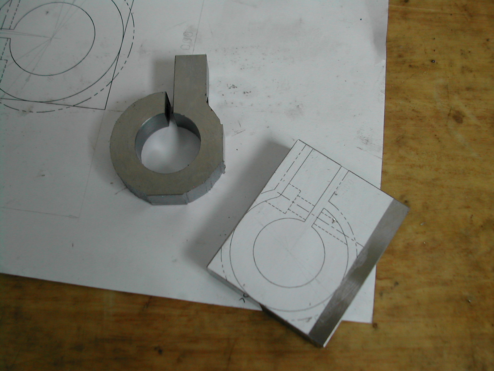 That full scale detail drawing sure comes in handy! Some quick work with a pair of scissors and a glue-stick and the parts are ready to have the waste removed on the vertical band saw.
 Now you see why I went ahead and put in the clamp screw and slit. I chucked up a piece of scrap in the rotary table, and milled a little stub arbor in-place. Then, crank the rotary table to 0°, slip one of the stops on the arbor, offset the spindle to the corner point of the stop plus one-half the tool diameter plus the machining stock amount. Then just swing the stop until it contacts the tool (with the spindle off of-course) and tighten the clamp screw securely. You can then mill the periphery of the stop.
 Here’s the finished clockwise and counter-clockwise stops. The angle and hole in the end were put in after milling the periphery.
 This is an inexpensive 2″ boring head with an R8 shank. I’ve modified the shank by turning down the taper and kissing the backside of the flange with the arbor running between centers in the lathe. A quick touch with the toolpost grinder insures a nice surface against the bronze bushing.
The actual diameter is not critical as I’ll be boring the bronze bushing to match. It just needs to be the same size or larger than the pilot diameter on the other end.
 In order to access the boring head adjusting screw when the ball turner is in operation, you need to flip the boring head slide around. Reed made a recess for the adjusting screw symmetrically on the other end of the slide. Doing it this way means that most of the time in-use the adjusting screw will be extended out of the boring head body.
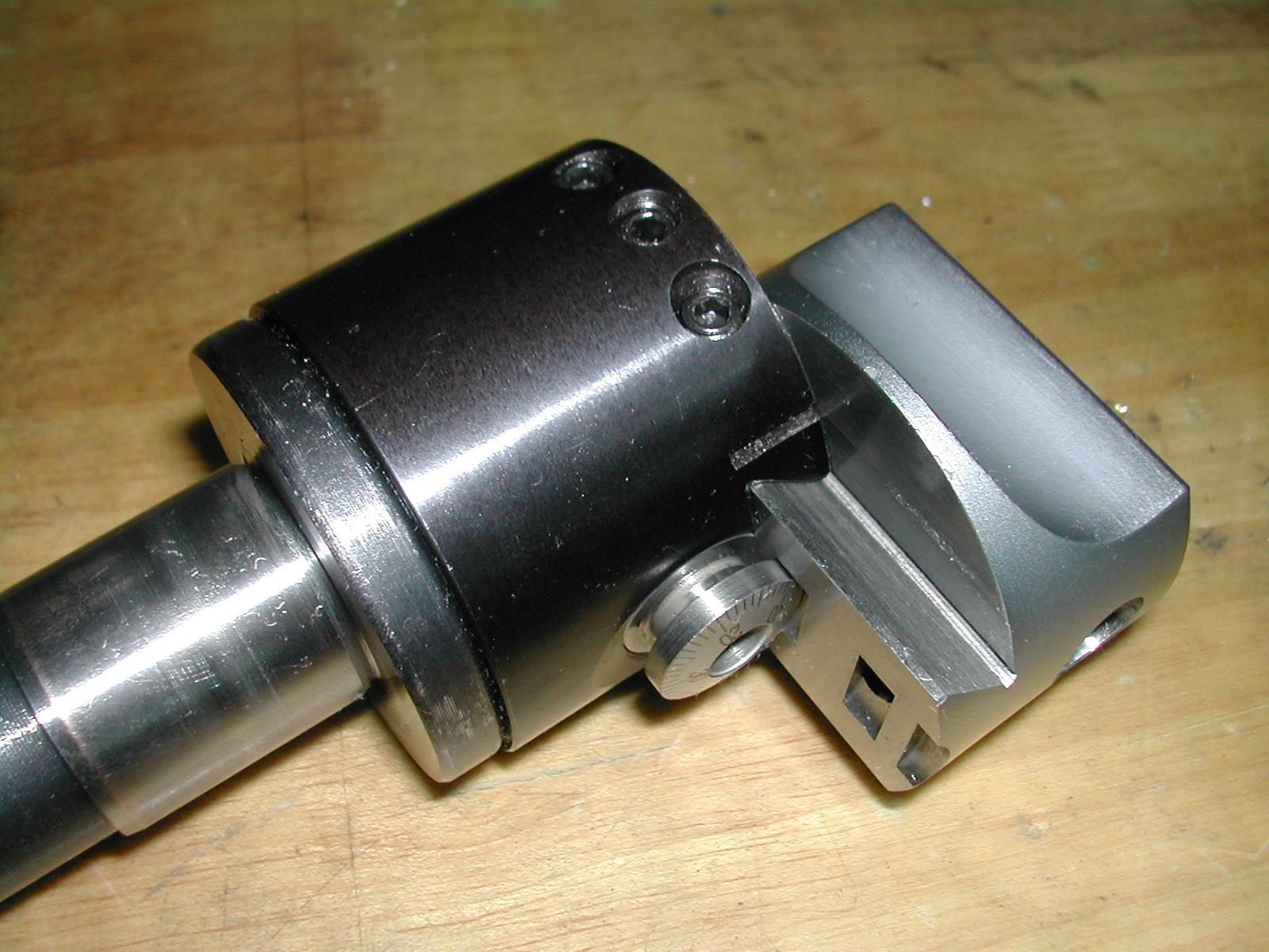
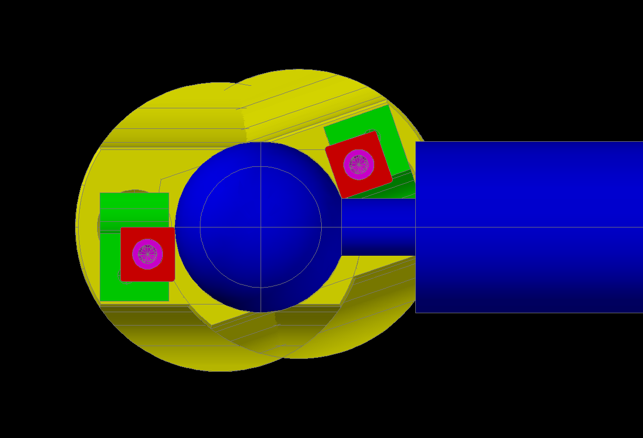
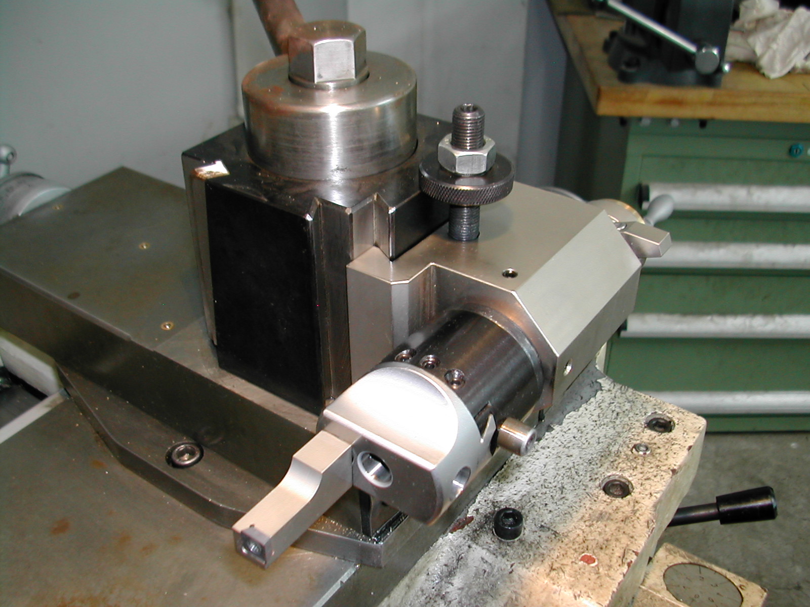
I chose cut a new recess in the center of the slide. This keeps the adjusting screw fully in the boring bar head head from the smallest ball sizes up to the capacity of the ball turner. the photo on the left shows the ball turner adjusted to it’s maximum capacity.
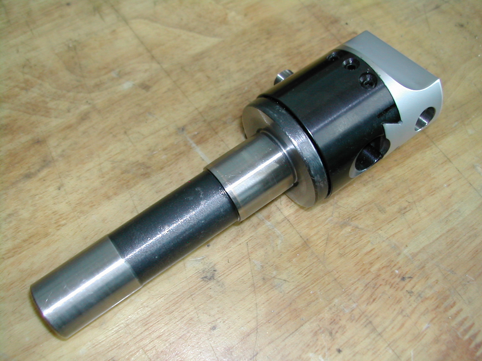
 The assembled body with the bronze bushings installed and bored to size. At the bottom of the photo you can see a threaded hole in the body. I’ve since added four of these, two on each end 90° apart, to take up any slack as the bushings wear, and to provide an adjustable resistance when rotating the ball turner.
The tapped holes are in the body only and do not go through the bushings themselves. Tightening the setscrews in these holes deforms the bushings a slight amount creating an interference fit against the ball turner shank.
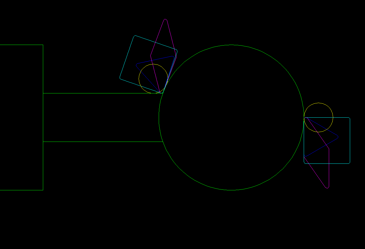 I knew I wanted to use a carbide insert on my boring bar so I modeled a few of the shapes of the smallest inserts I could find. The diamond inserts need the shortest neck to be roughed in on the part, but also have the toughest pocket to create and only two cutting edges per insert. The round inserts are the easiest to fabricate a toolholder for and have theoretically infinite cutting edges, but they leave the largest radius between the ball and shank.
 I chose the the 3/8″ square milling inserts for my first toolholder. They were easy to find both here in China and later when I get back to the States, plus they have four edges per insert, and the pocket geometry will be fairly easy to machine.
 I fabricated my toolholder out of an M24 grade 12.9 socket head cap screw. That’s the easiest way to get pre-heat-treated good quality steel here in China. I pre-drilled the three corner holes, roughed out the pocket with a 6mm end-mill, and then finished milled the angled sides with a 2mm carbide end mill running as fast as my spindle would go (3000rpm).
Light cuts and a lot of Tap-Magic produced a very nice pocket which the photo does not do justice to. I didn’t have any new inserts at the time so I used one I took out of my face mill for testing. It was coated with anti-seize, and got the new pocket all messy.
 The final step was to drill and tap the pocket for the insert screw. This hole was offset to insure that the insert was pulled tight against the pocket when tightened.
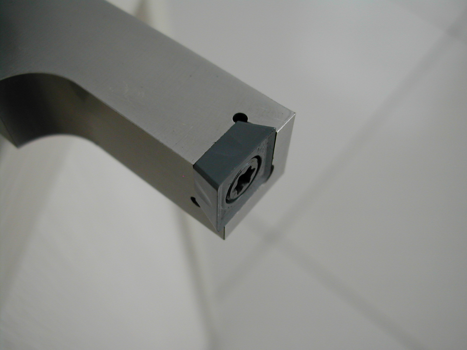
 The pocket is designed to hold the insert flush with the end of the holder and to allow the cutting edge to extend past the holder by the amount of the 7° taper.
When used as a over-the-top ball turner in the lathe, the cutting surface is the end of the boring bar, not the normal face found on regular boring bars hence the need for a special holder.
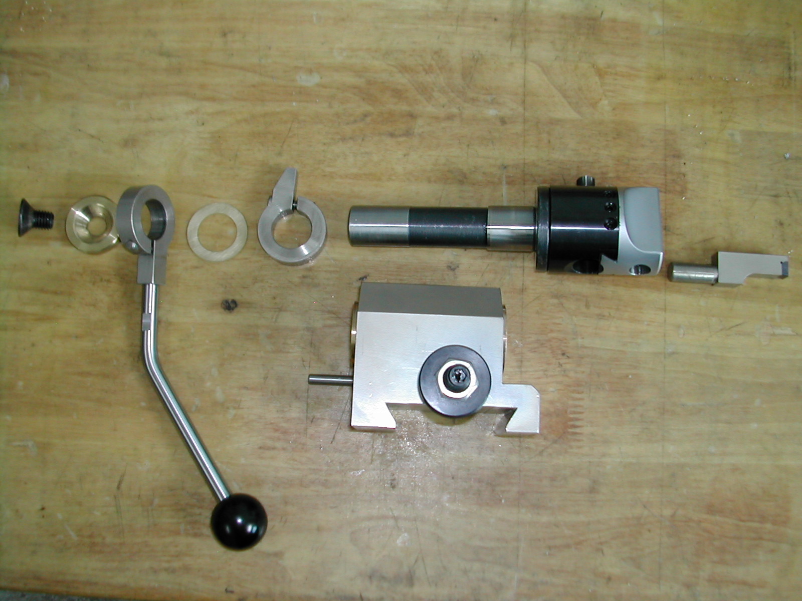 Here are all of the pieces laid out, cleaned, and ready for final assembly.
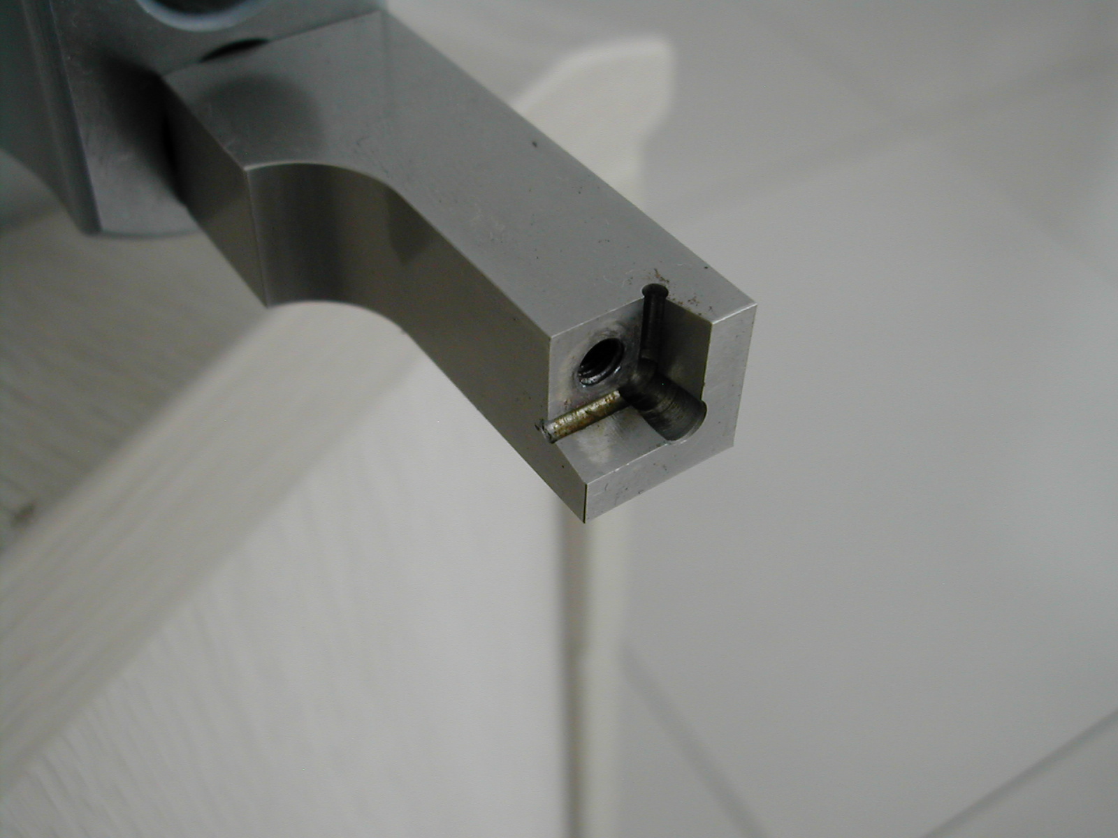
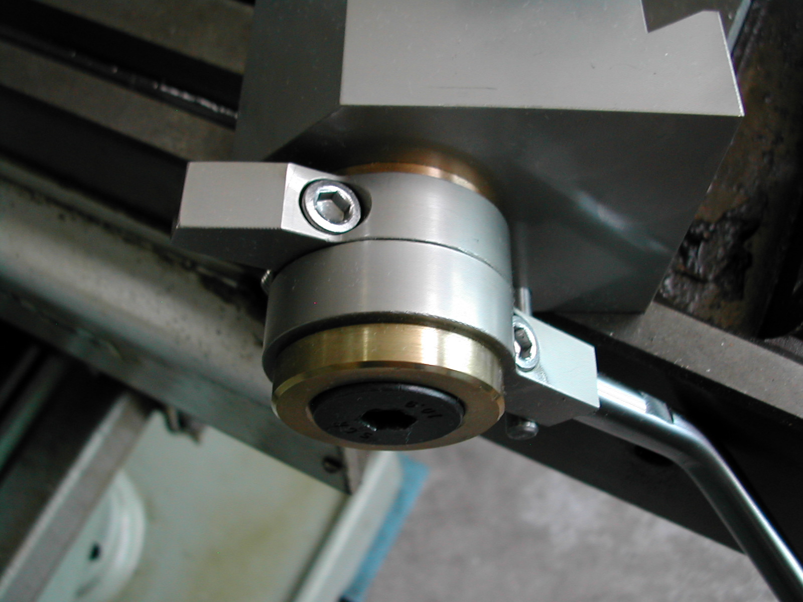
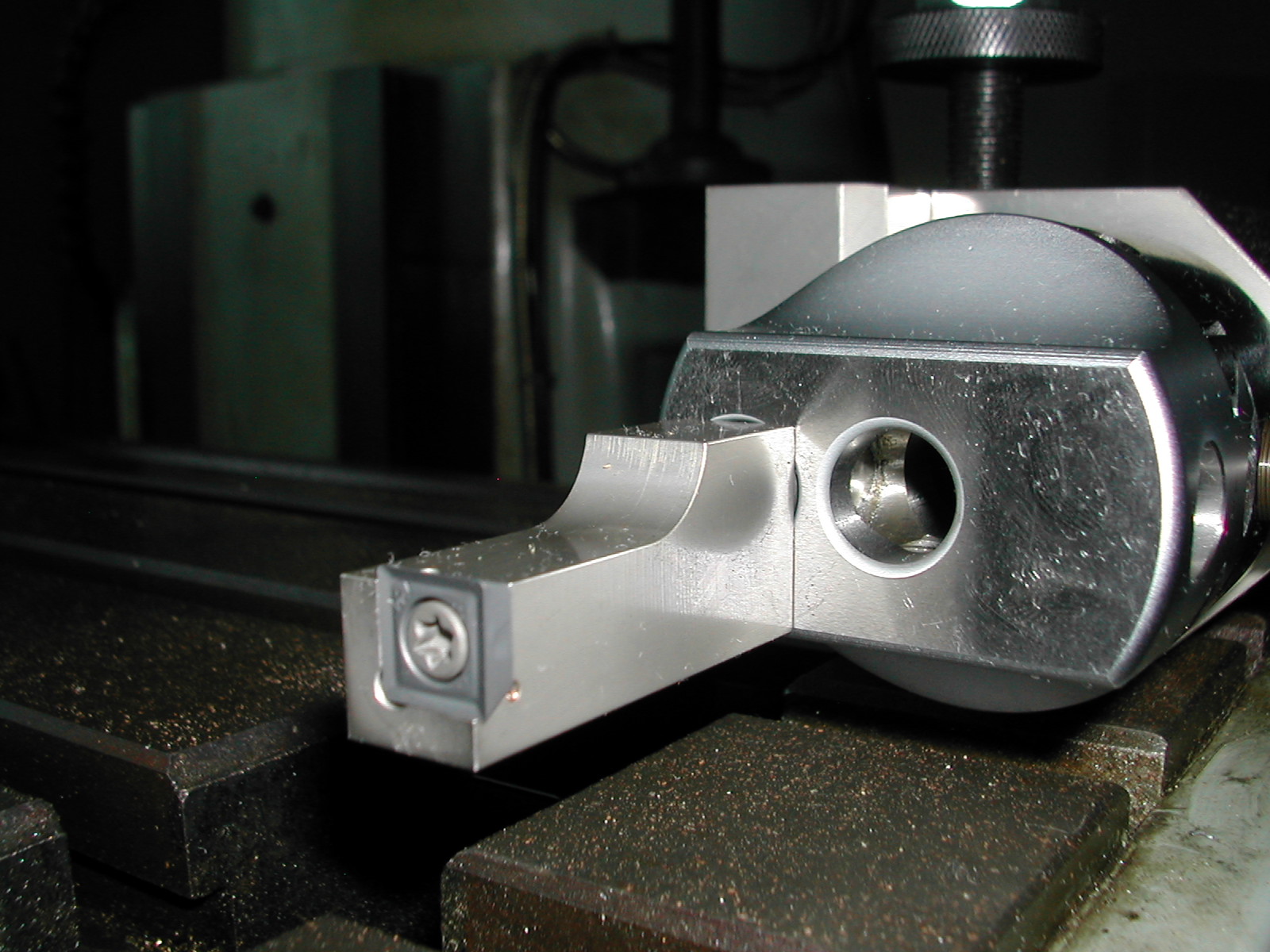 The boring bar inserted into the outboard hole for turning medium to large balls.
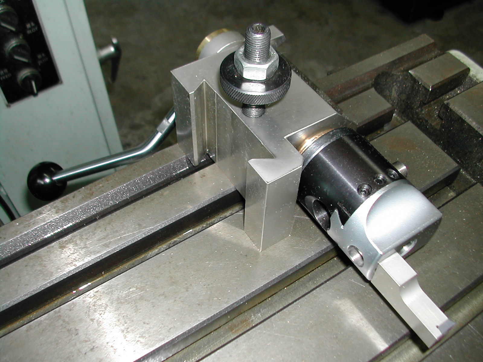 Test assembly and adjusting the brass spacer between the two stops to remove all traces of end play.
 The back end assembled with the brass spacer between the stops. I’ve since modified the counterclockwise stop with a small screw for fine adjustments to the neck diameter setting.
 Test assembly and adjusting the brass spacer between the two stops to remove all traces of end play.
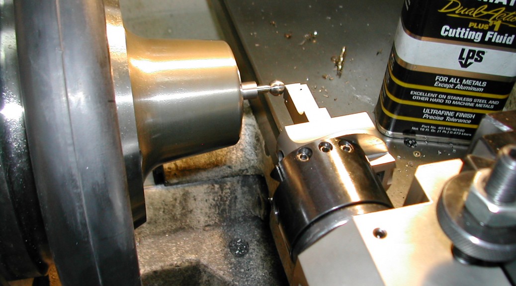
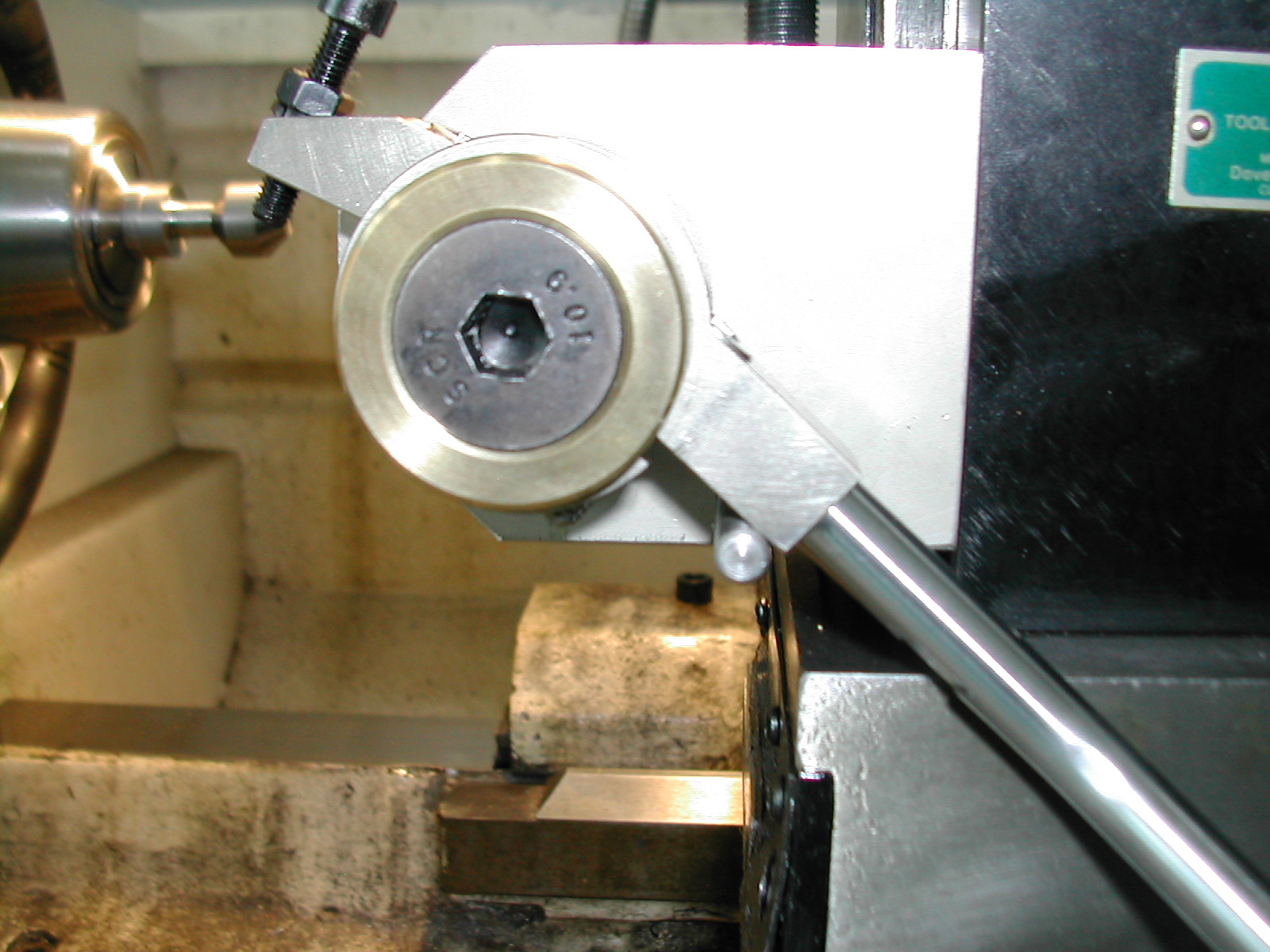
 Setting the diameter and tool height. Loosen the clockwise stop clamp screw so the boring head is allowed to turn freely to position the tool at both the top and bottom of the round bar. Using both the boring bar adjusting screw and the toolpost height adjusting screw, adjust the boring bar until the insert just touches both the top and bottom surfaces when rotated.
 Once this initial setting for the tool height is found, it should not need to be changed again for this toolpost and lathe combination. In the future, to set the tool for the ball diameter, just turn the ball turner to position the tool on the top surface, and crank the boring head adjuster until the insert touches.
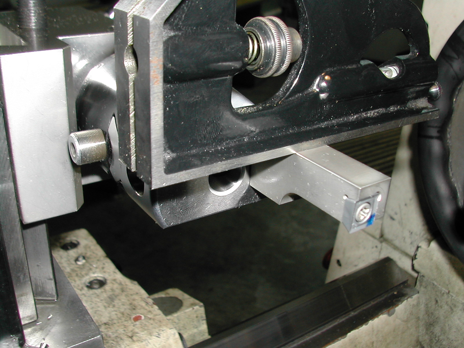
Using a level to rough set the clockwise stop. Once this setting is finalized, it should not need to be changed again either.
 Here we see the clockwise stop against the pin while we’re using the level on the other end to set the tool position. With the stop against the pin, the boring head is rotated until the boring bar is level then the stop’s clamp screw is tightened.
This photo also shows the subsequent modification of the counter-clockwise stop to add a fine adjustment to control the neck diameter setting.
 In use, the ball turner is set up by first setting the boring head diameter until the insert just touches the top surface of a pin that is the finished ball diameter. The the ball turner is rotated against the clockwise stop, some light facing cuts are taken on the stock to determine the X-axis center location and this cross slide reading is recorded.
The lathe carriage is locked in place at the last facing cut location, and the cross-slide backed out. Balls can now be turned by advancing the cross-slide a small amount, rotating the ball turner from the clockwise stop to the counter-clockwise stop and back cutting a small amount of material off the ball. These two steps are repeated until the cross slide is advanced to the X-axis center position.
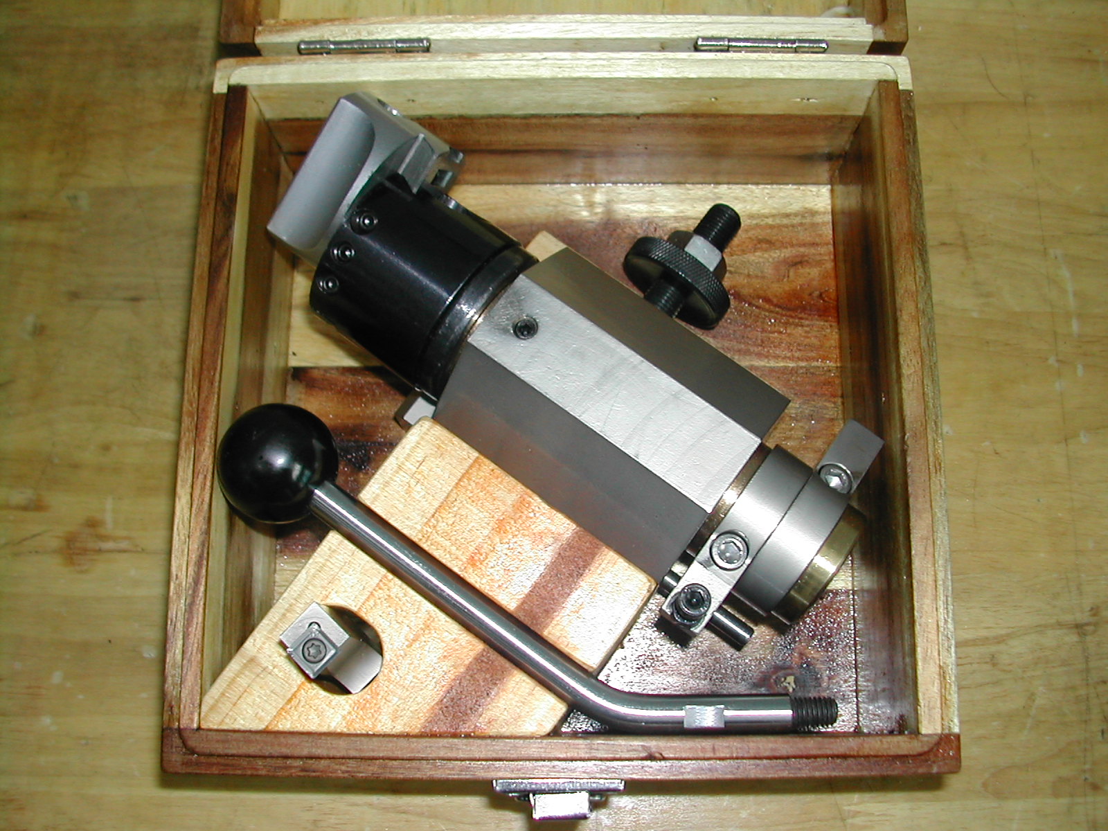 Finally, every nice piece of tooling deserves its own fitted storage box. There’s some blocking inside the dovetail area on the bottom of the box to hold the turner in place and some more blocking on the lid to securely hold the three items down when the lid is closed.
Since making this ball turner, I’ve used it for making my Quorn ball handles and for radiusing the wrist pins for my Hodgson Radial. I couldn’t be happier with its performance and accuracy.
Disclaimer and License
All material, including the CAD drawings, relating to the construction of the Ball Turner presented on this site is free to use any way you see fit. However, no guarantees are made regarding the accuracy or correctness of the material presented here.
CAD Files Used On This Page (AutoCAD 2008 Format)
Ball Turner (1.5M .zip)