
- Ball Turner Design
- Ball Turner Manufacture
There are times in the machine shop when you need to make a spherical ball out of metal. You can form grind a tool and plunge the sphere on the lathe, or like Reed Streifthau of the Quorn Owners Yahoo Group, you could use an inexpensive import boring head to make a ball turner. Starting from Reed’s design, this page attempts to document what I came up with.
I wanted a more rigid mount, so I decided to incorporate the Aloris CA size quick change holder into the ball turner itself. I also wanted to use an indexable carbide insert for the actual cutting edge because of the ability to swap in a new cutting edge without having to re-adjust all the settings. I did use the same 2″ cheap import boring head (well, in my case, it was a domestic boring head since I’m living in China right now), but I modified it slightly differently than Reed. Hopefully, these changes will become clearer as you read down the page. Enjoy!
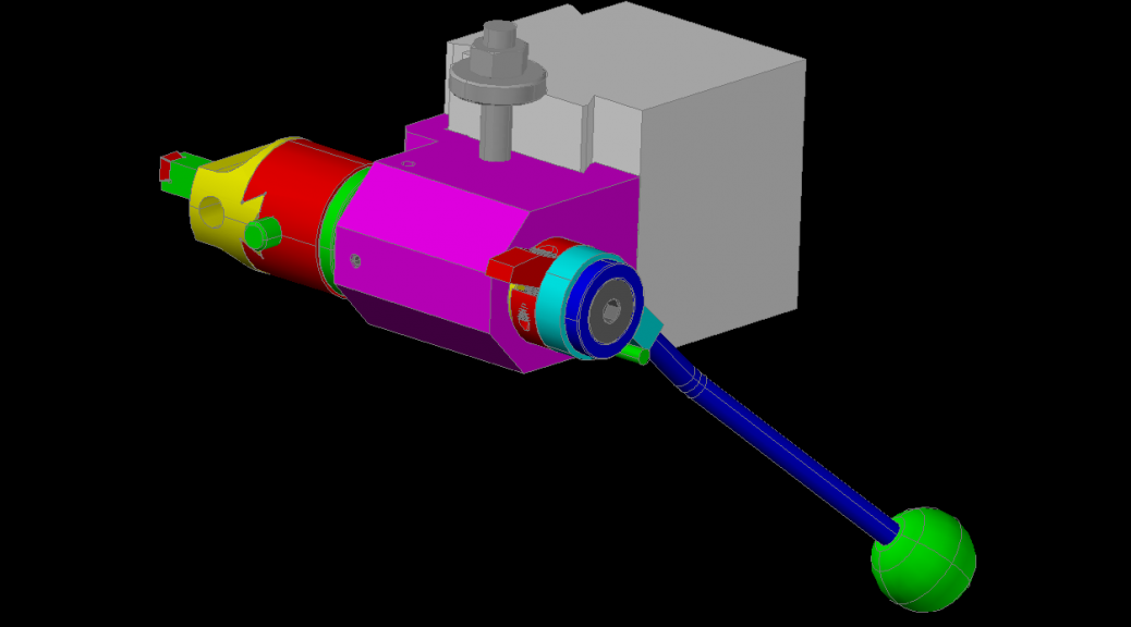
 As always, I start with a full CAD solid model of what I’m attempting. This allows me to work out in my head how all the parts will fit together as well as the sequence of operations I’ll need to follow once I get in the machine shop and start cutting metal. It’s no fun to finish one operation like milling a surface, then realize that you no longer have a way to hold the part for drilling the next hole.
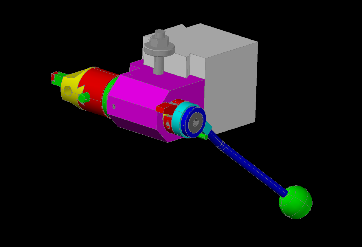
 Most of the operations for creating solid models are boolean operations like adding and subtracting one solid from another. For the most part, this is directly analogous to machining operations. Thinking out how to build the solid model get’s you 90% of the way to building the part in metal!
Next: building the tool