
- Hodgson Part 091, Rear Cover Casting
- Hodgson Part 092, Air Guide
- Hodgson Part 095/096, Carburetor Mount & Lock Cylinder
 The carburetor mount was made from a 0.75″ x 1.3″ x 2.4″ piece of Aluminum 7075-T6, while the lock cylinder was made from Ø5/16″ yellow brass. I change the lock cylinder to a full split cotter, adjusted the outside perimeter of the carb mount to better match my rear cover casting, and reduced the size of the mounting studs to #10 to better fit the overall scale of the carb mount.
 You might want to refer to the rear cover build log and start the carb mount before doing the rear cover to save yourself a little time.
You’ll need to make the split cotter lock cylinder first so that the cove cut can be made when the bore is machined in the aluminum mount. To start the lock, I faced off a piece of the rod to 0.810″ and drilled and tapped it #6-32 through. My tap wasn’t long enought to tap all the way through, so I tapped about 3/4 of the way from one side and 1/4 from the other.
The side where I went in 3/4 of the way will end up as the tapped half of the cotter and is marked black for my reference.
 I squared up my block of 3/4″ aluminum and drilled and reamed the Ø0.3135″ hole for the split cotter through the long dimension.
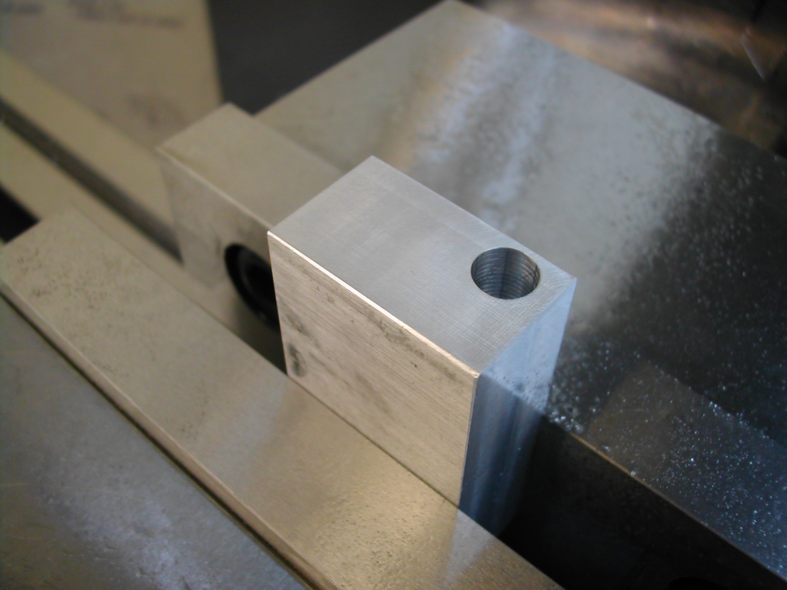
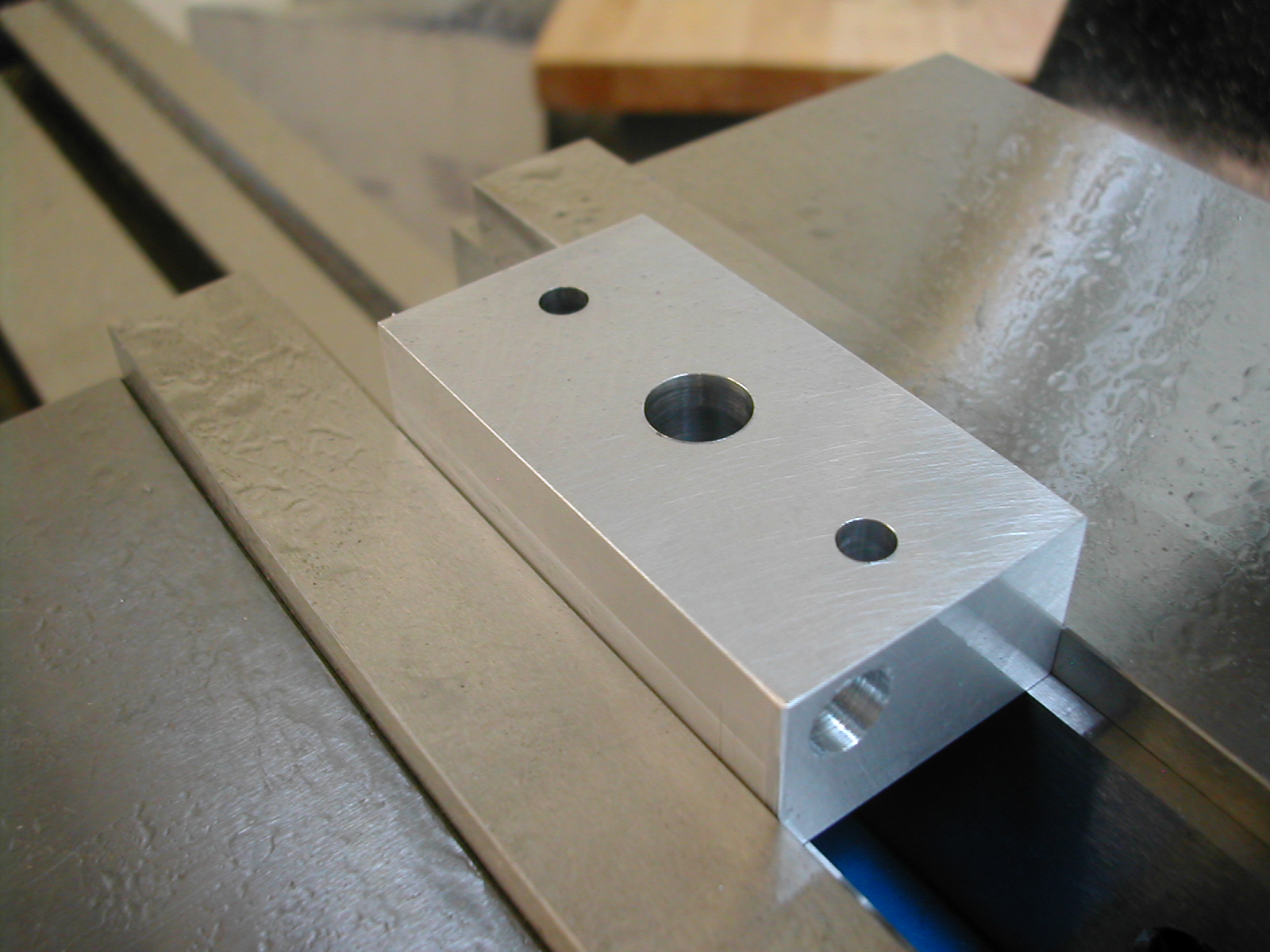 Since the block is 1/8″ oversize in thickness, I’m clamping on a little less than 1/4″ so I can profile the mount boss in the next operation. With the block clamped, I drilled for the #10 mounting studs, and roughly drilled the center bore to 7/16″.
 The mount boss was then profiled to the finished width of 0.812″ and the lock cylinder installed with a #6-32 screw and washer from each side of the boss to hold it securely in place for machining at the same time as the carburetor bore.
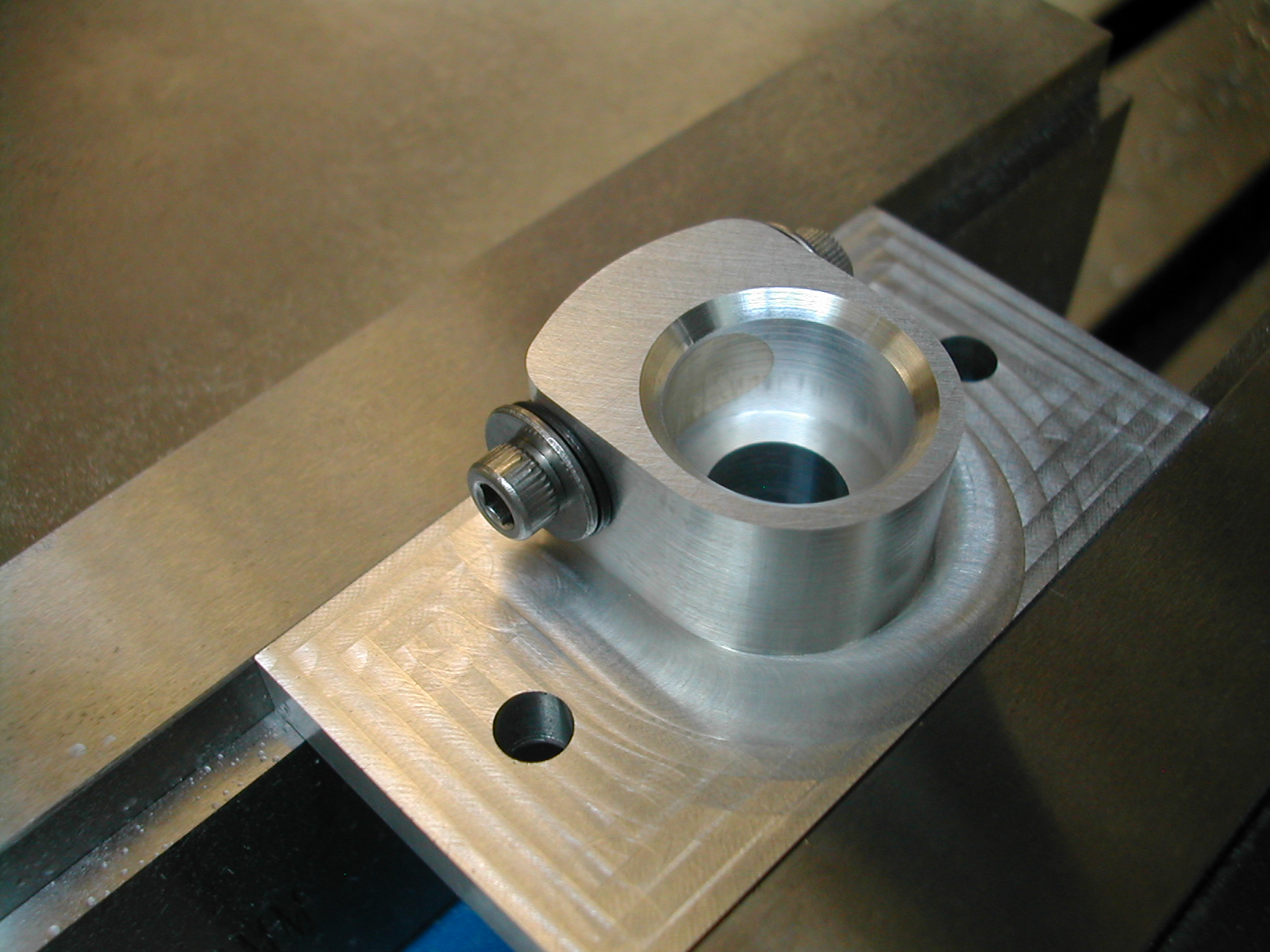 Here is the finished Ø0.590″ carburetor bore (I did verify that this diameter and depth was correct for the O.S. 60KC carb I am using), and you can clearly see how well the lock cylinder machined.
I have also added a 0.052″x45° chamfer for a 1x15mm o-ring to seal the carb body to the mount.
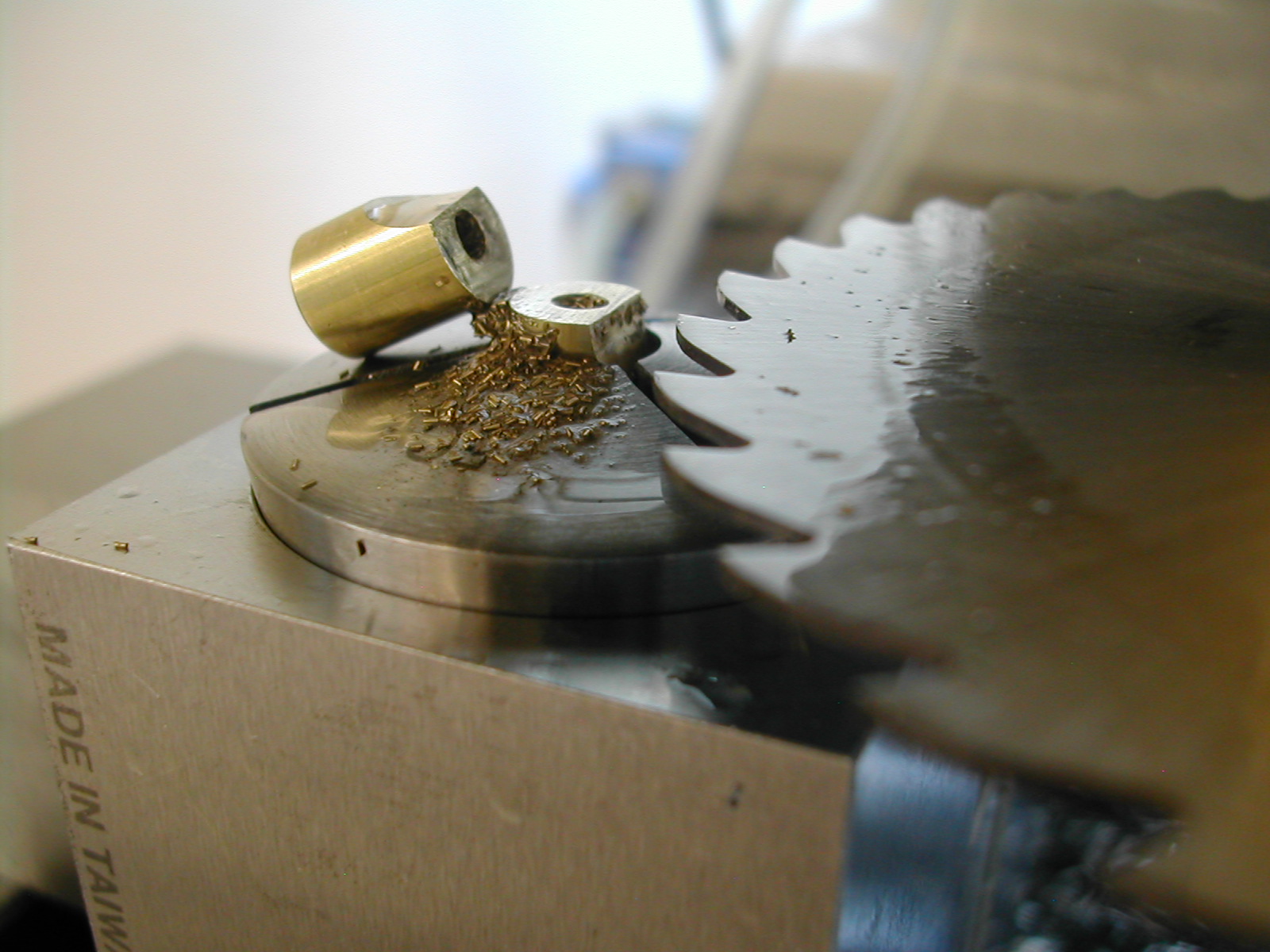 To finish the lock cylinder, I cut it in half with a 0.040″ slitting saw and drilled one half (the half with the imperfect threads) with a #28 drill.
 Next, the back was milled to the finish flange thickness. I chose to do this in the mill instead of the lathe as I thought it would be more secure and less prone to chatter.
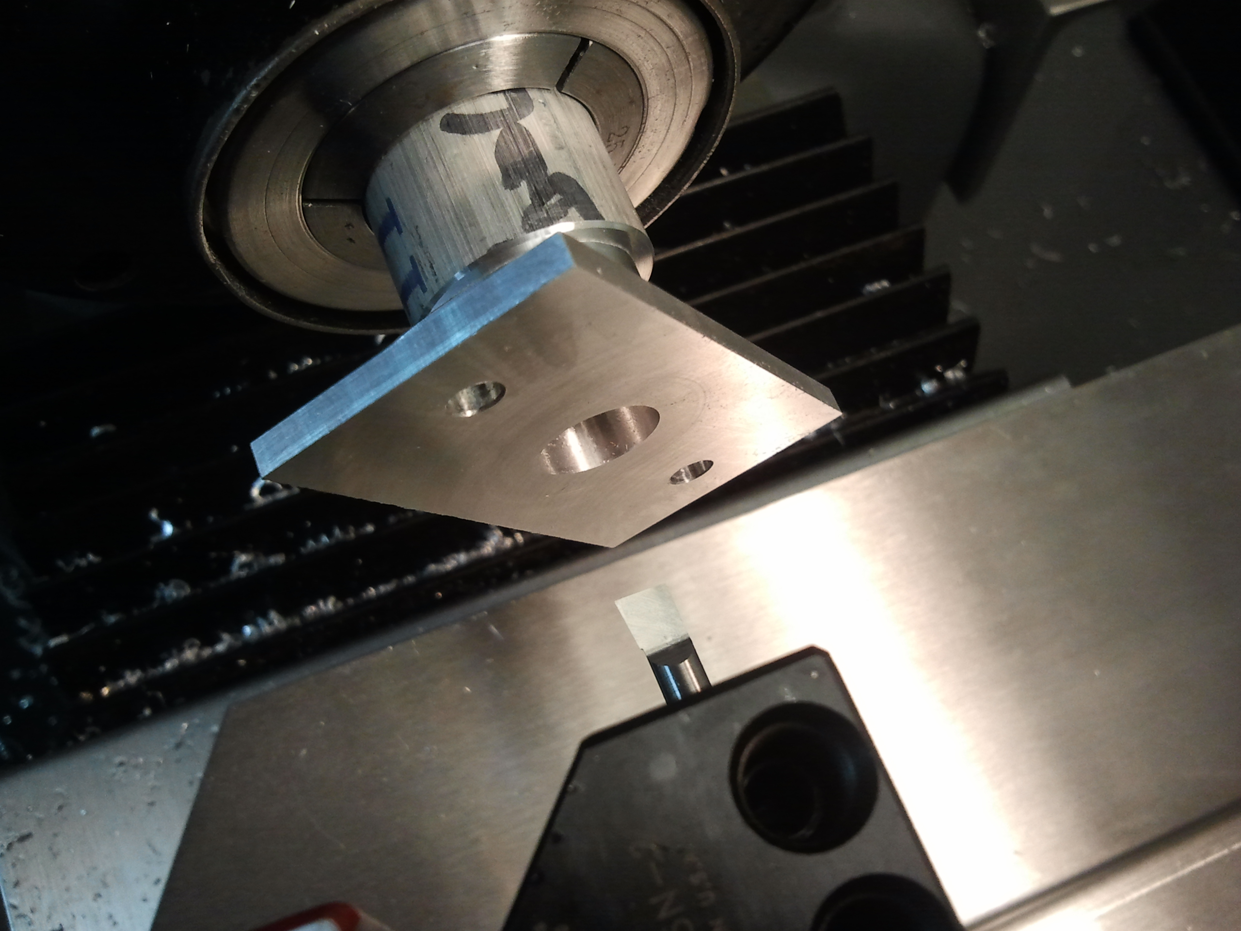
 A stub arbor is turned on the lathe to stand in for the carburetor so we can attach the carburetor mount using the split cotter to turn the blend taper and add an o-ring groove to the back side.
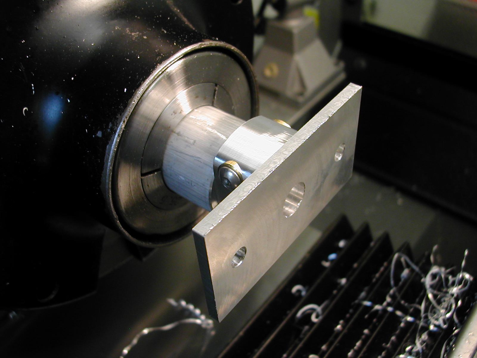 Here the carb mount is affixed to the stub arbor and secured using the split cotter.
 Here I’m machining the transition taper to match my Ø0.488″ carb outlet to the Ø0.500″ air horn starting diameter. This equates to approximately 1.47° per side for my O.S. 60KC carb.
 Another modification I made was to add an o-ring groove to fit a 1x15mm o-ring to the back of the carb mount to seal agaist the end of the air horn.
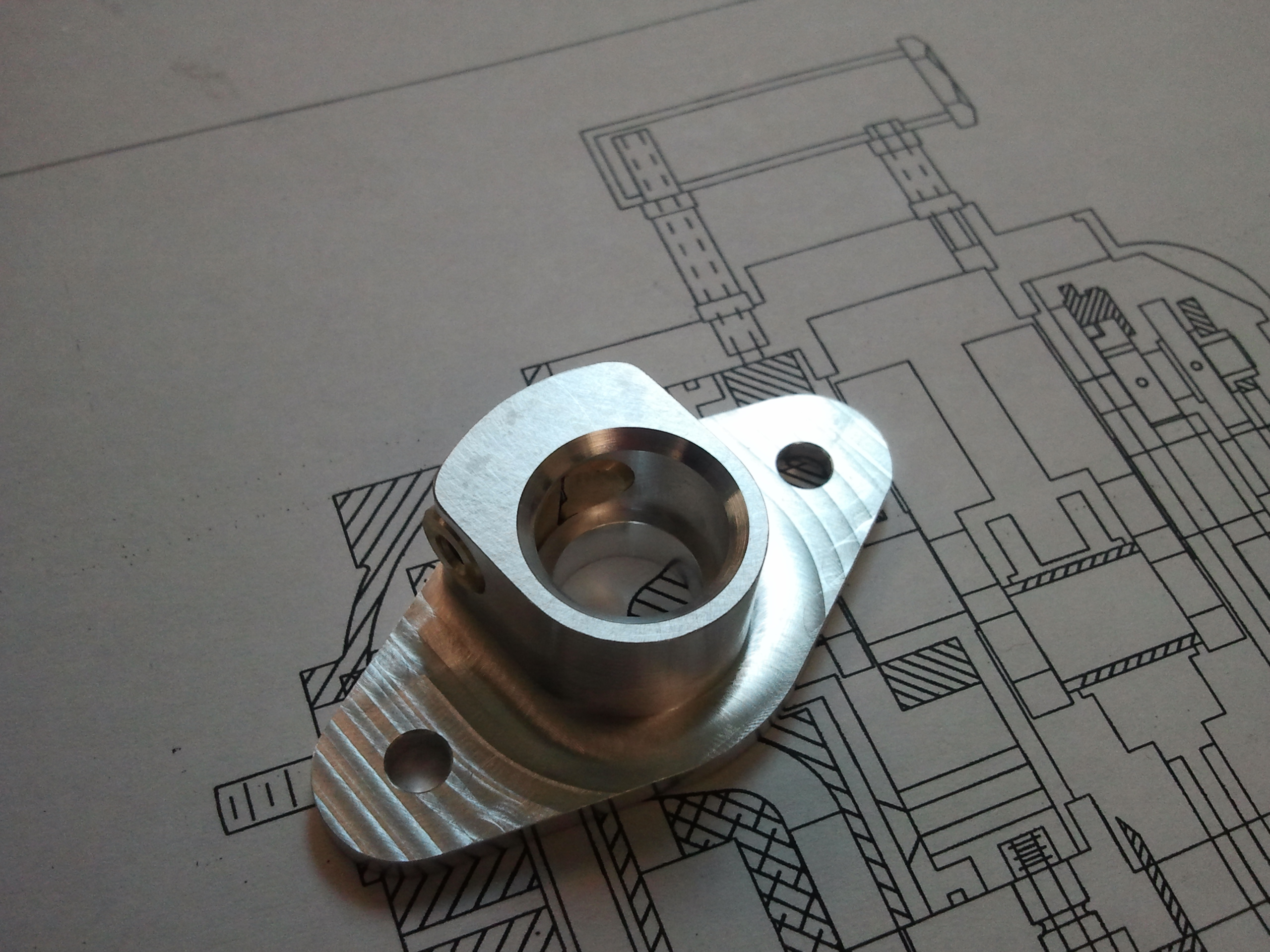
 Here I’ve mounted my rear cover casting to a tooling plate using the #6 perimeter screws and attached the carb mount using the #10-32 studs and nuts.
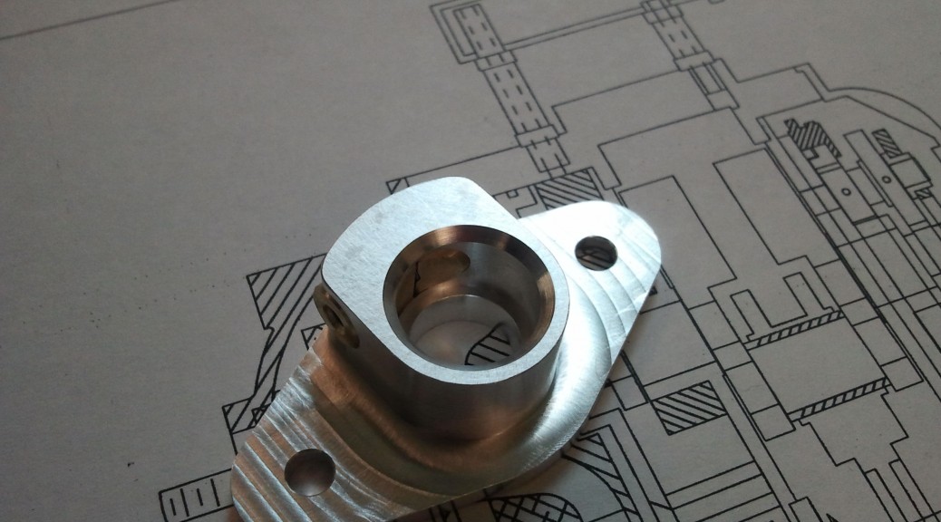
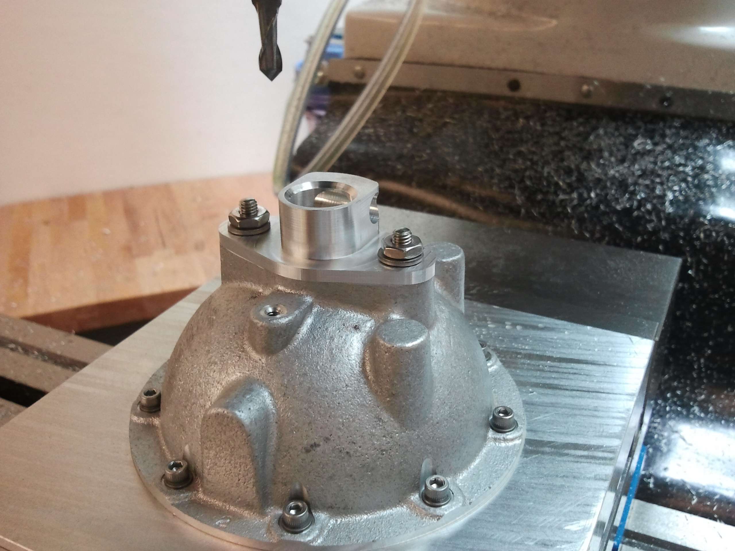 Using a 1/4″ chamfer mill, I’m profiling the carb mount with the straight side of the cutter and using the tip to machine a chamfer wherever the carb boss on the rear cover doesn’t exactly match the profile. You can just see a little bit of the chamfer cut on the left side.
And here is the finished carb mount. If I do this again, I’ll use a bullnose cutter to cut the boss so there will be a nice chamfer between the boss and the flange.
Disclaimer and License
All material, including the CAD drawings, relating to the construction of the Hodgson Radial presented on this site is free to use any way you see fit. However, no guarantees are made regarding the accuracy or correctness of the material presented here.
Links Used On This Page