
- Hodgson Part 077, Oil Pump Housing
- Hodgson Parts 079-083, Oil Pump Gears & Shafts
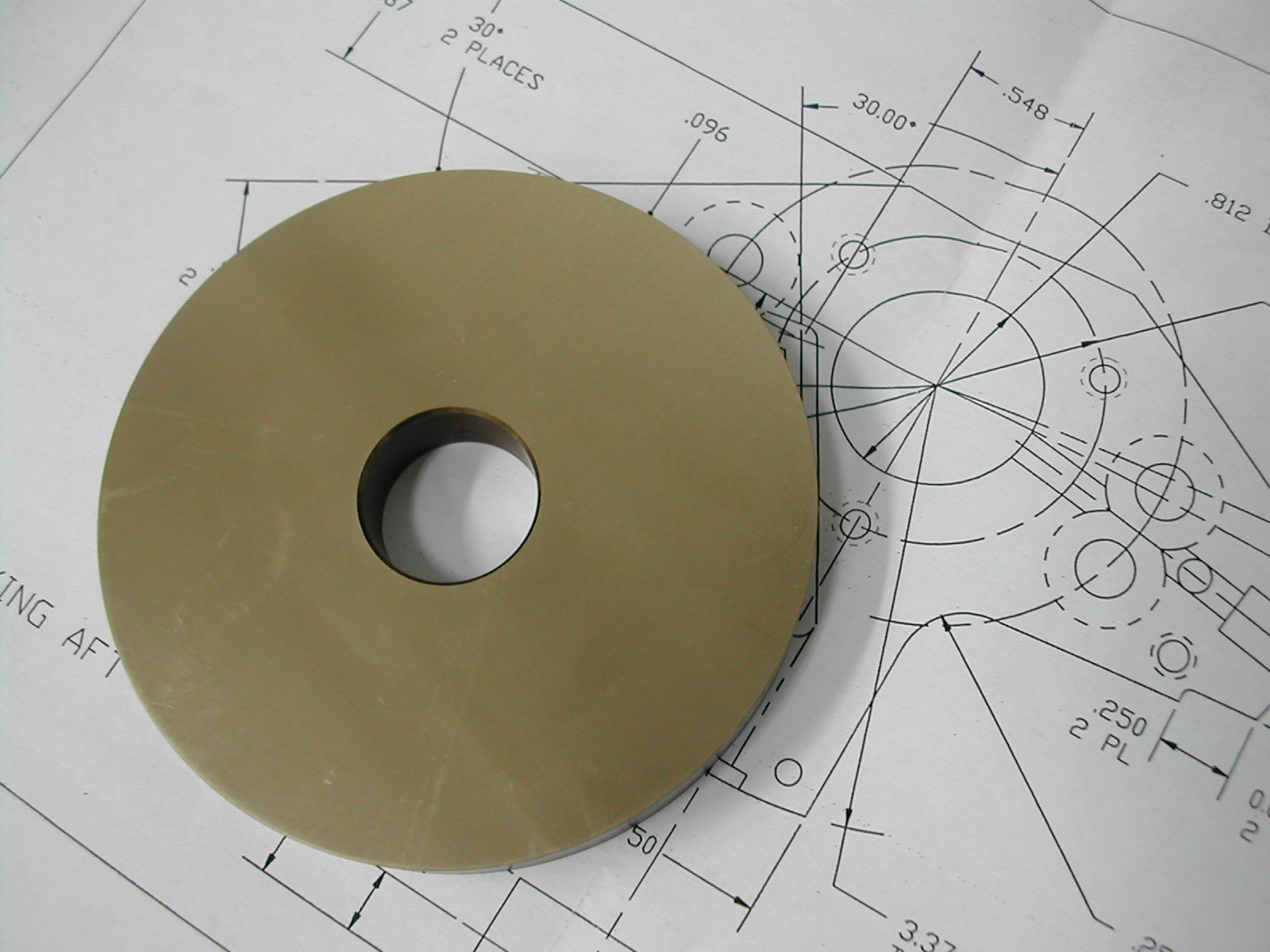
 For the oil pump housing, I chose C63000 nickel aluminum bronze (known as QAL9-4 bronze here in China). This material has high strength because of the added nickel and good wear resistance. The downside is this material is very “grabby” and tends to warp if you get it hot. Therefore, I’m going to machine it in two phases with a stress relieving operation in-between.
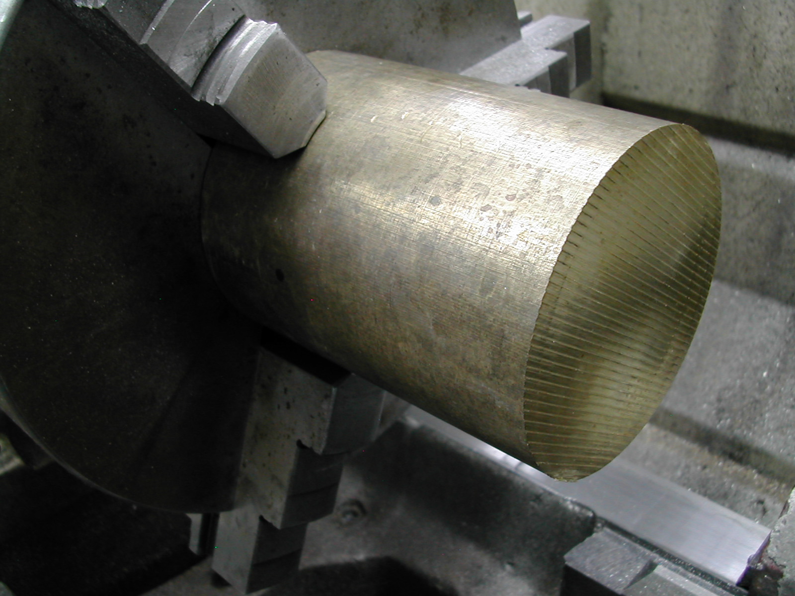
 First I began by facing the end of the stock and turning the 3.374″ O.D.
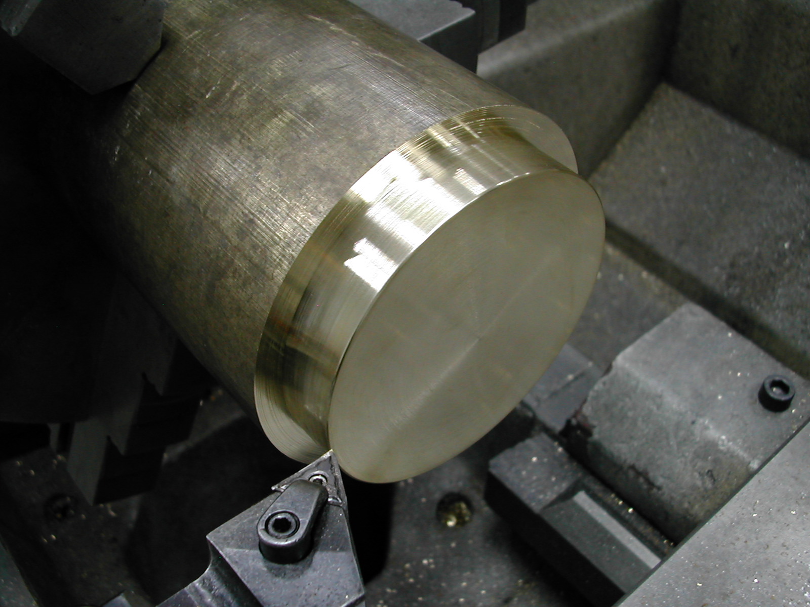
 The bore is added next. Since I had previously turned the rear bearing, I matched this bore for a snug slip-fit over the bearing.
 Don’t forget a small chamfer to clear any fillet on the rear bearing.
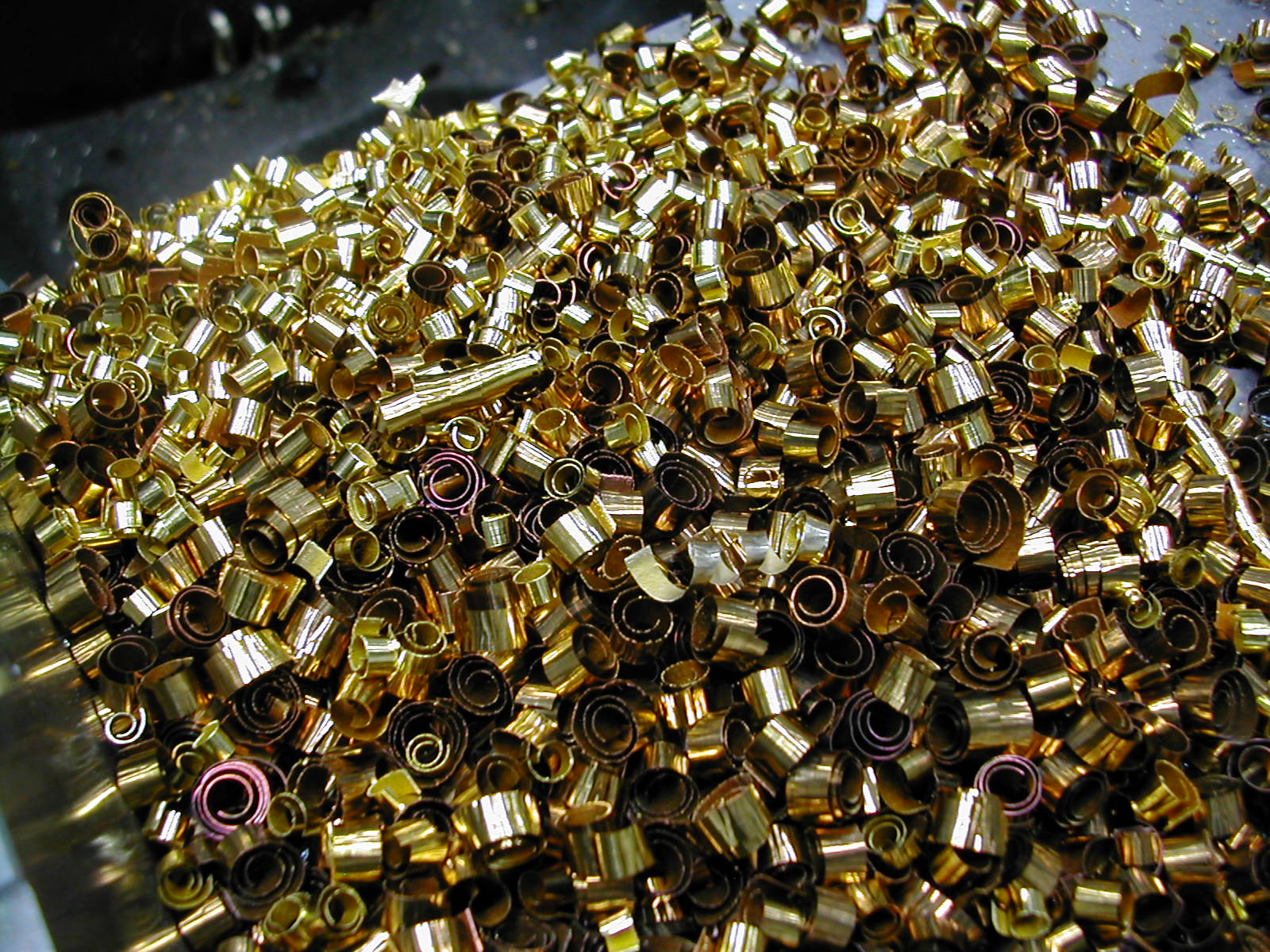
 Next the blank is parted-off from the stock. This is a potential problem area where a lot of heat and warpage can be created. Be sure to use a sharp tool and lots of coolant.
I’m leaving some extra stock here to finish grind both faces after stress-relieving.
 This is a lot of expensive material going to waste.
 After 2 hours at 400°C to stress relieve the part, both faces have been ground to the 0.465″ finished thickness.
Before proceeding on to hole drilling, you should have completed the rear bearing so that the gear shaft holes can be align reamed in both the pump housing and bearing.
You should also consider completing the turning operations on the front bearing so that can be drilled in the same mill setup.
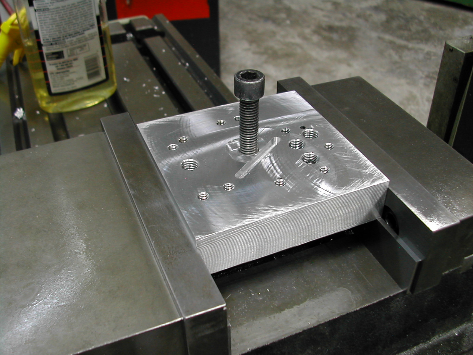 A simple drilling fixture for the oil pump housing was made from a scrap of aluminum. The scrap was faced after clamping in the vise to be sure it was perpendicular to the mill spindle and a M10 hole was tapped near the center.
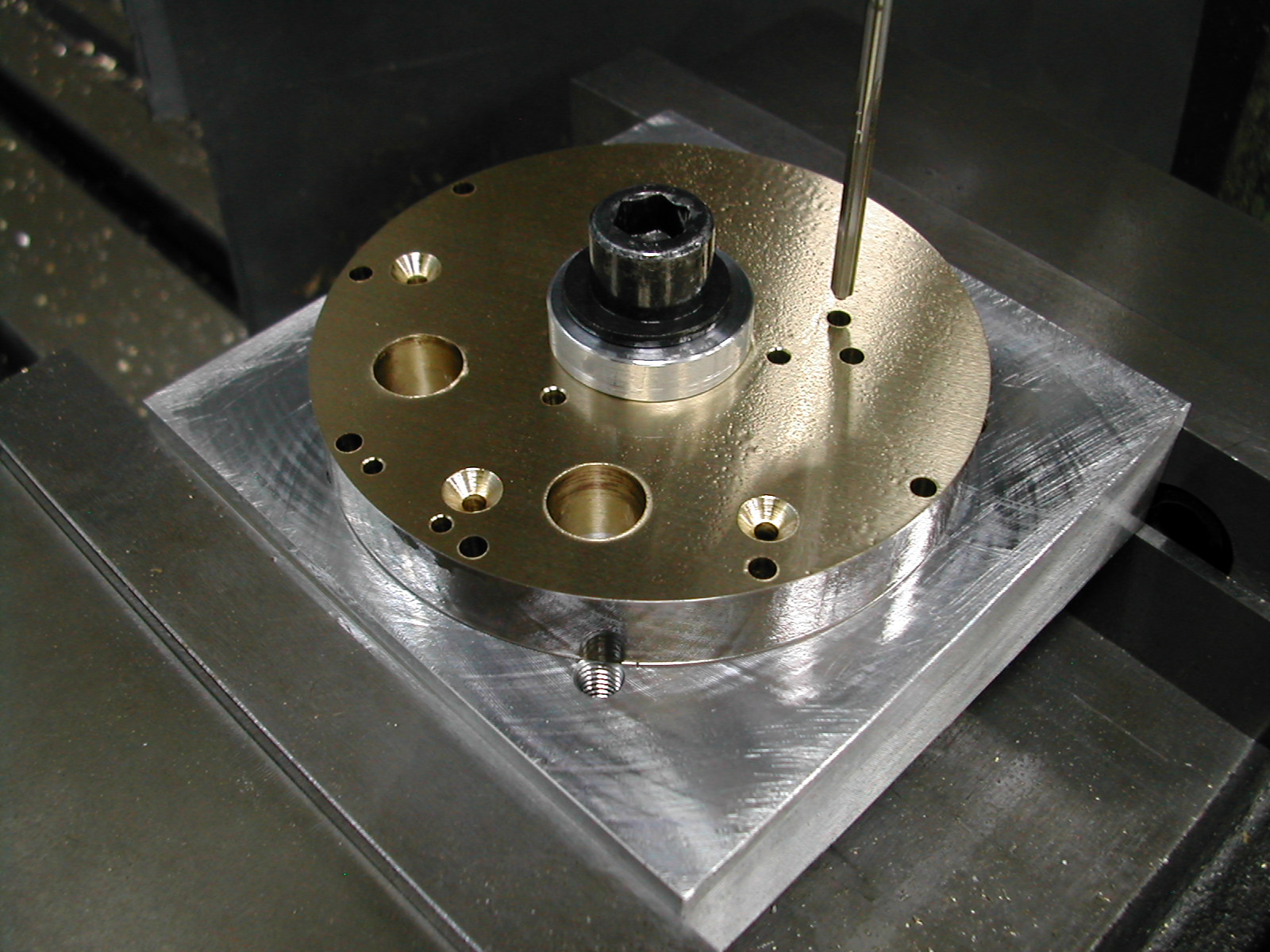
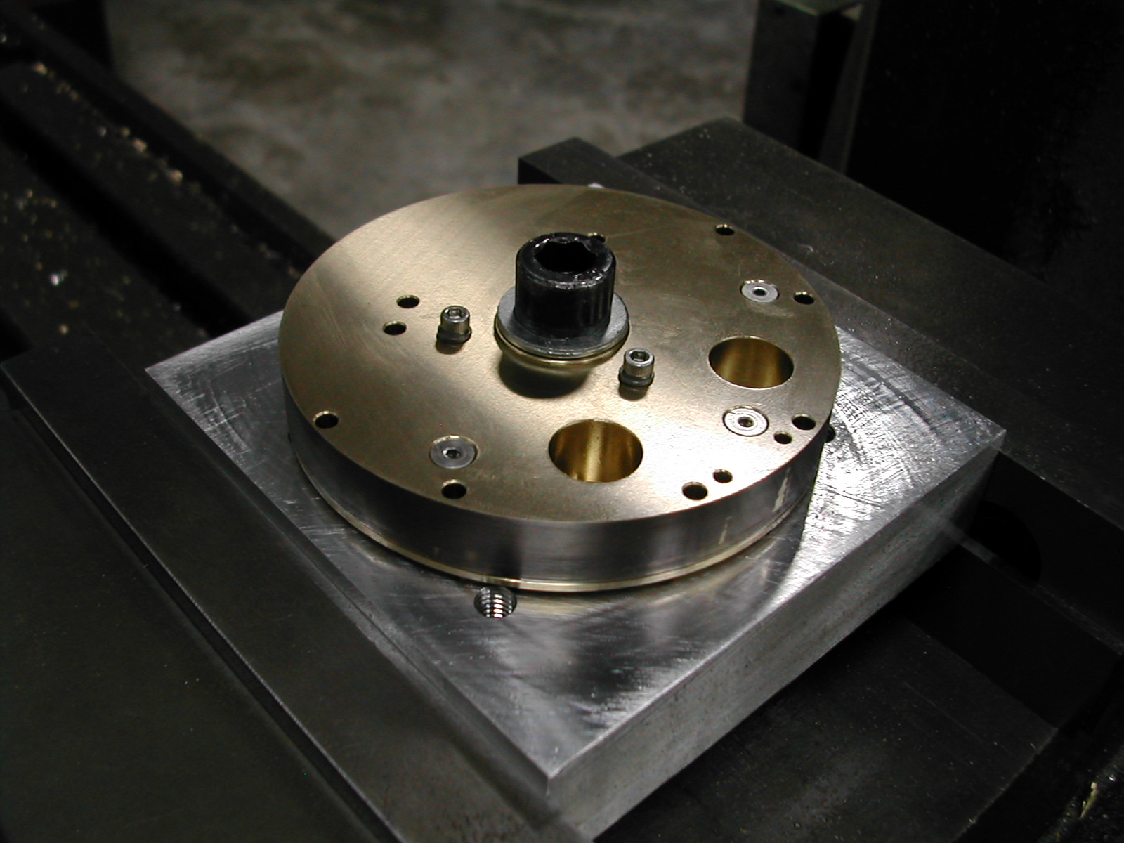
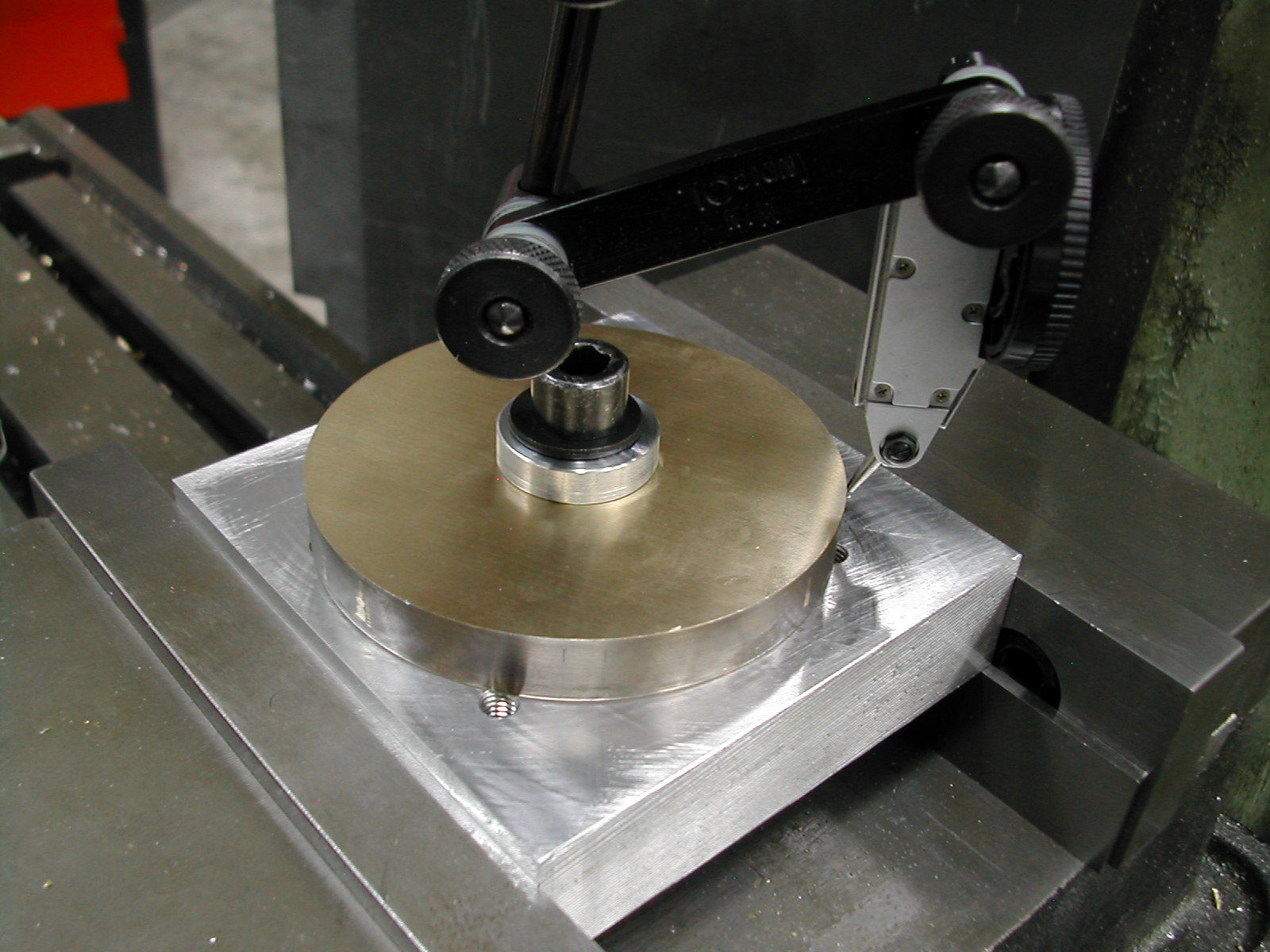 The oil pump housing was then clamped to the tooling plate with a M10 SHCS an aluminum washer. The center of the housing was then located by indicating the housing O.D.
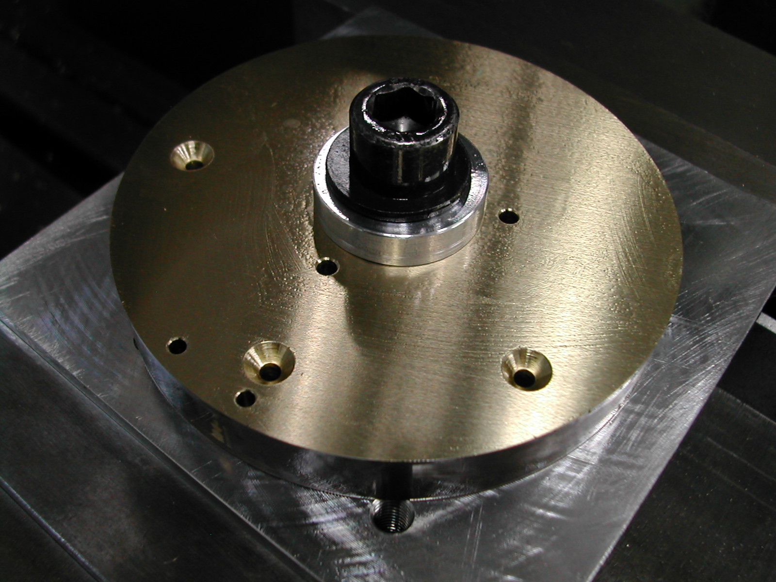 Here I’ve drilled the three #4 clearance holes around the center for the SHCS. I’ve also added an additional #4 countersunk hole along the suction pickup arm for a total of three of these as well.
This is all of the “standard” holes, other than the gear shaft holes, in the housing.
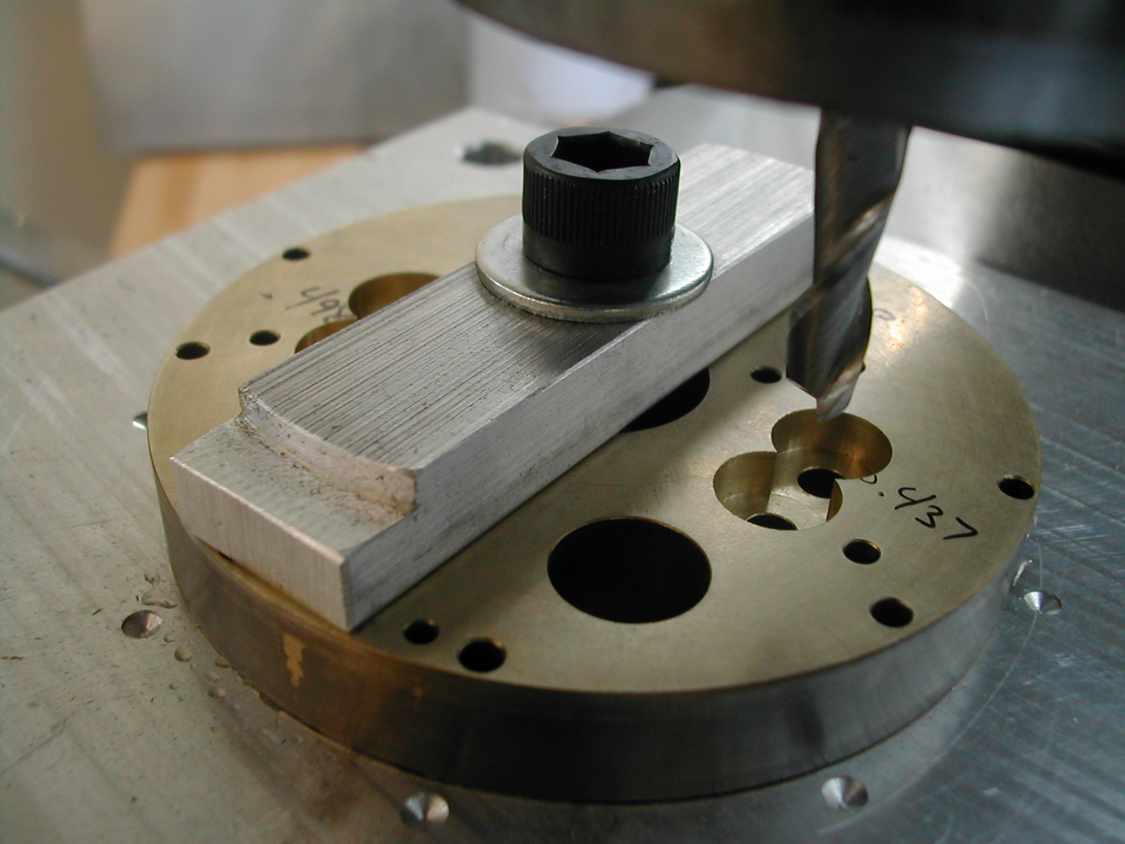
 Now, I’ve added a whole bunch more. There are now 10 reamed 0.126″ holes and two larger holes. These will be used later to generate the profile of the oil pump. Here is the housing process sheet that explains the new additions.
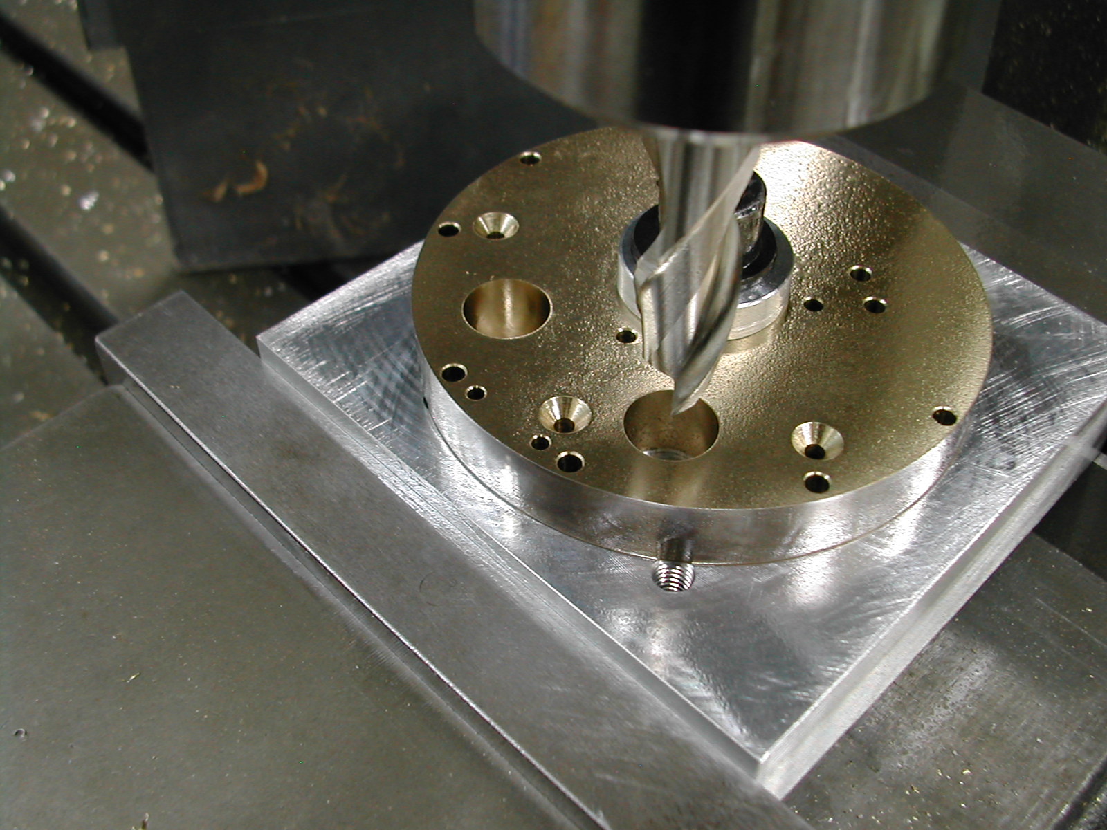 Instead of reaming the two 0.500″ holes, I just ran a 1/2″ endmill through them to get them to size with a nice surface finish.
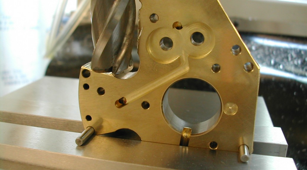
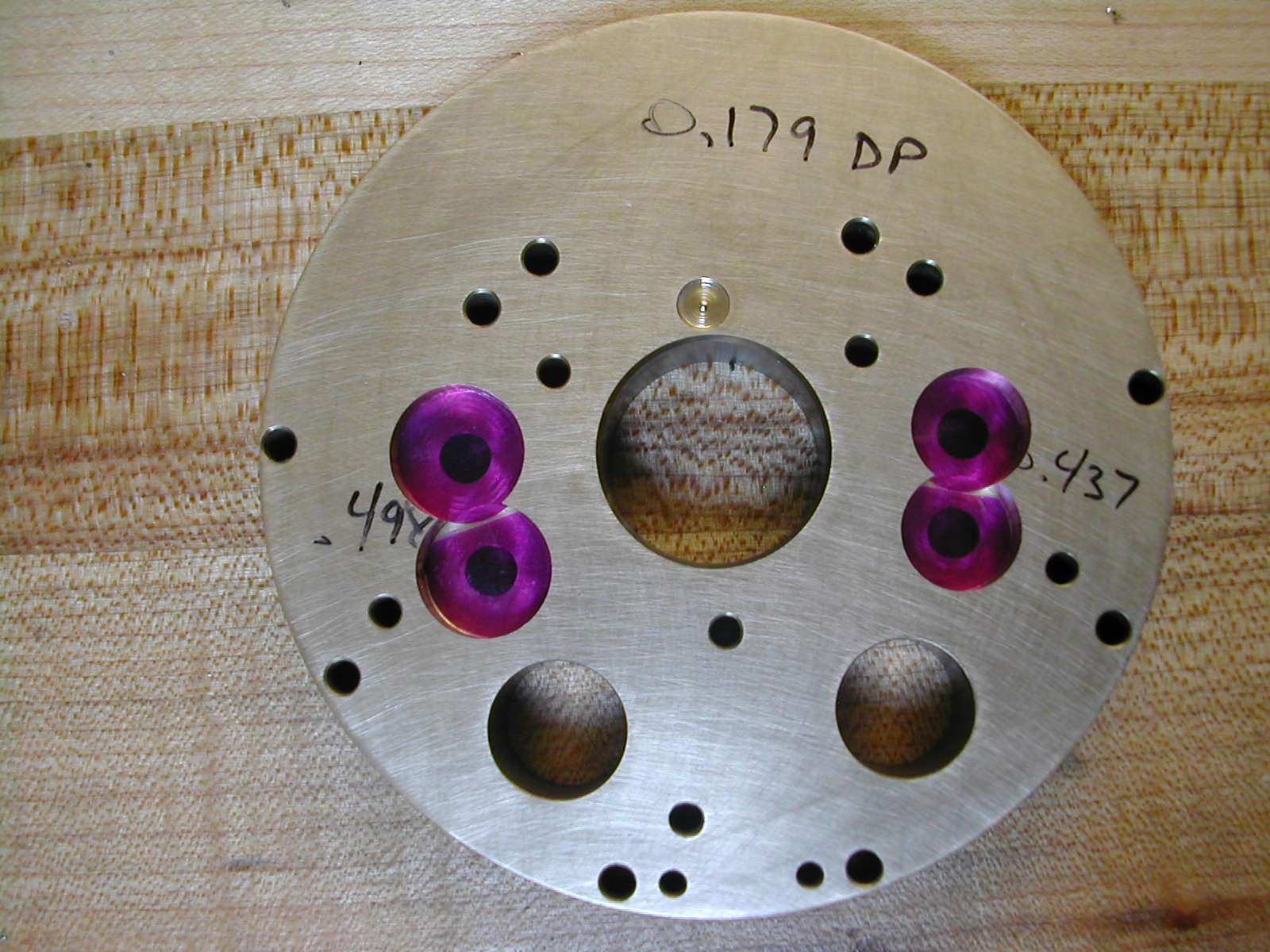
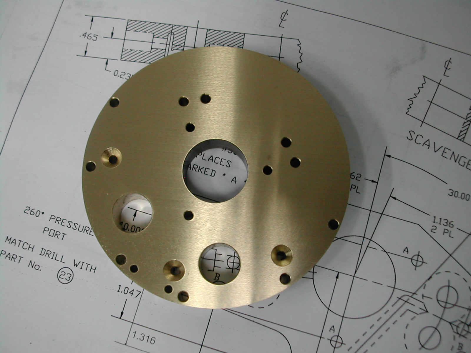 Here is the partially complete oil pump housing removed from the drilling fixture.
 Before any further work can be done to the housing, the gear shaft holes need to be align reamed with the rear bearing. Once all of the oil pump mounting holes have been tapped in the rear bearing, work can proceed on the oil pump housing.
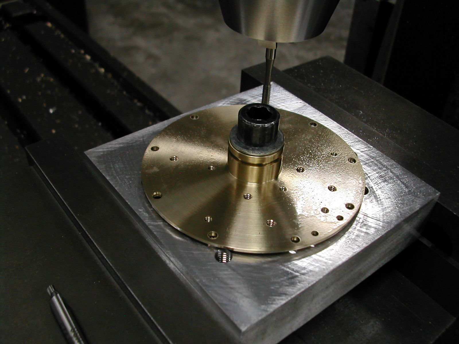
 Without removing the rear bearing from the fixture and loosing the location, the oil pump housing is attached. Here you can clearly see the extra #4 flat head screw on the bottom of the oil pump housing.
 The four 0.188″ holes for the gear shafts are now reamed through both the oil pump housing and the rear main bearing at the same time.
 All of my gears were a different width, so I machined the gear cavities to the depth of the narrowest gear. In my case, this was 0.179″.
 After the gear pockets were machined, I cut some 0.001″ shim stock and placed it in the bottom of the gear cavities.
 I pre-lapped one side of each gear on 1200 grit paper and placed the lapped side down against the shim stock in the bottom of the cavities. I then preceeded to lap the entire pump housing with the gears in place.
 It appears that I got caught up in my work and forgot to photograph the oil passage milling. For this, first I plunged the three vertical passages with a 1/8″ ball-nose endmill and milled a short slot at the main bearing connection with the ball-nose cutter as well.
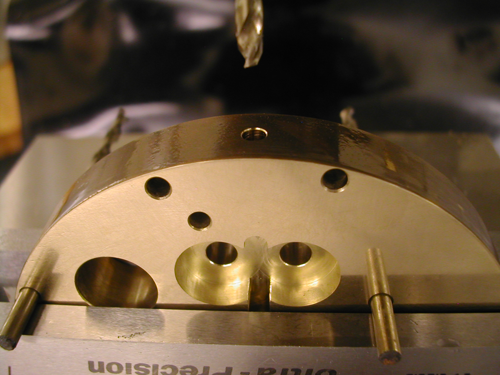
Next all of the horizontal connecting passages were cut with a 1/8″ flat end mill. Then with 1/8″ pins in holes “A” and “D” resting on the top of the vise jaws, I drilled the 1/8″ perimeter connecting holes for the suction and pressure ports.
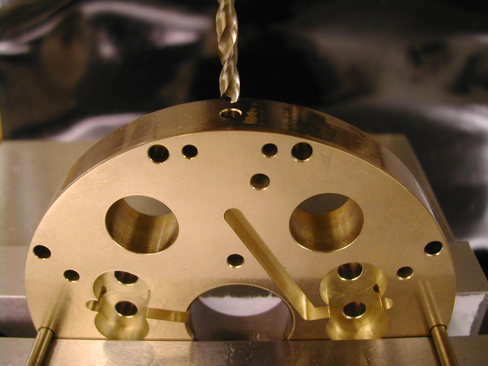 Here I’ve got pins in both of the “C” holes to line up the sump oil passage for drilling. For right now, I’m going to stop with the 1/8″ drill – I’ll do the rest of the work on all of the ports after match drilling with the Crankcase ports.
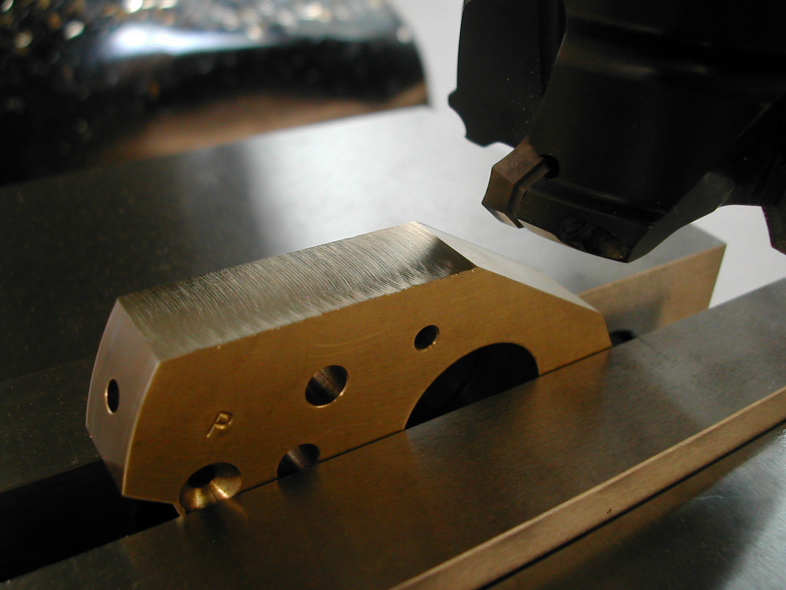
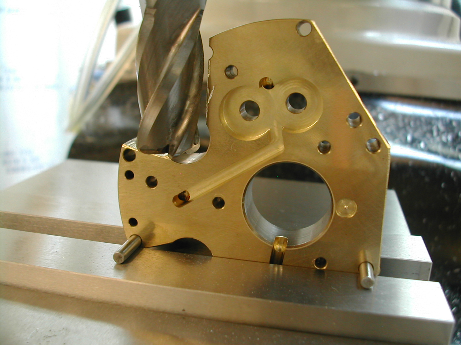 0.125″ diameter pins are inserted into holes “A” & “E” to orient the housing to mill surface #1 on my housing process sheet.
 Surface #1 is complete 0.005″ after hole “B” cleans up.
 At this point you can put in the little step needed to clear the head of one of the rear bearing mounting screws. Now, repeat these last two steps for the other side.
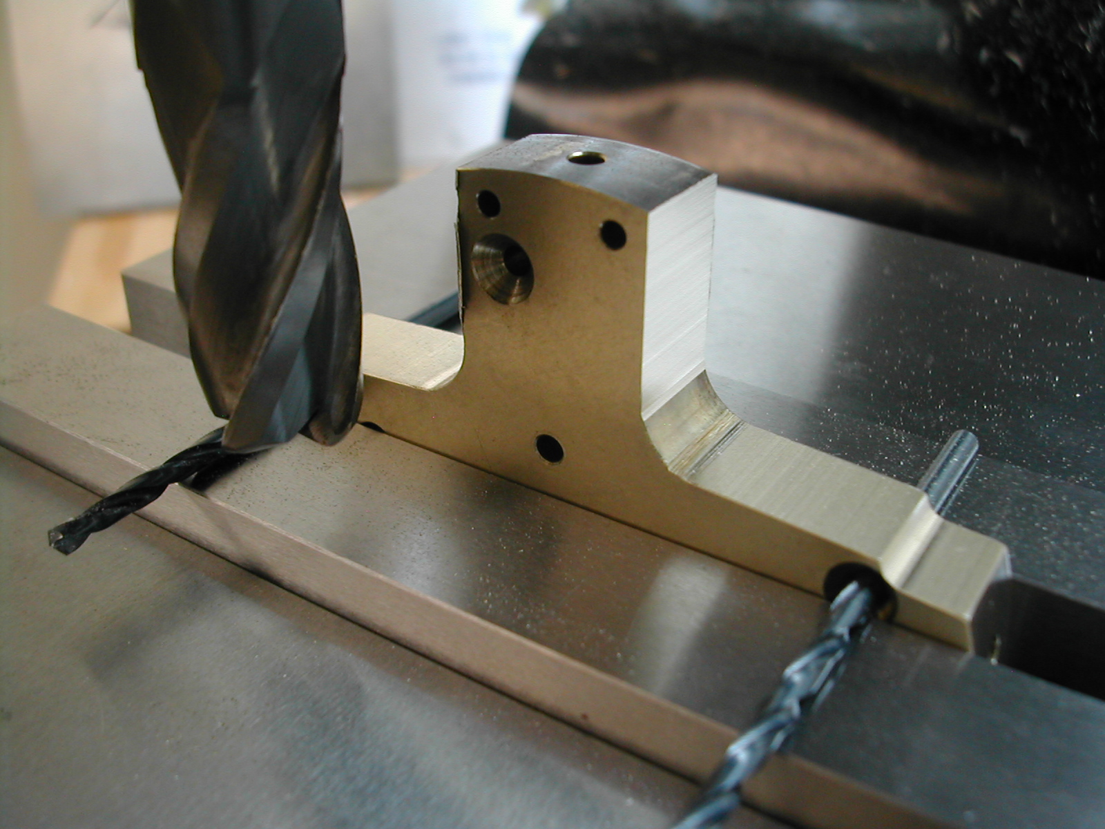 Using a couple of #33 drill bits in the two “B” countersunk screw holes, mill both sides of the sump arm. Again, these surfaces finish 0.005″ after hole “A” cleans up.
 Flip the housing over and insert two 0.125″ pins in the holes labeled “C” and mill surface #3. This surface finishes 0.005″ after the two holes marked “E” clean up.
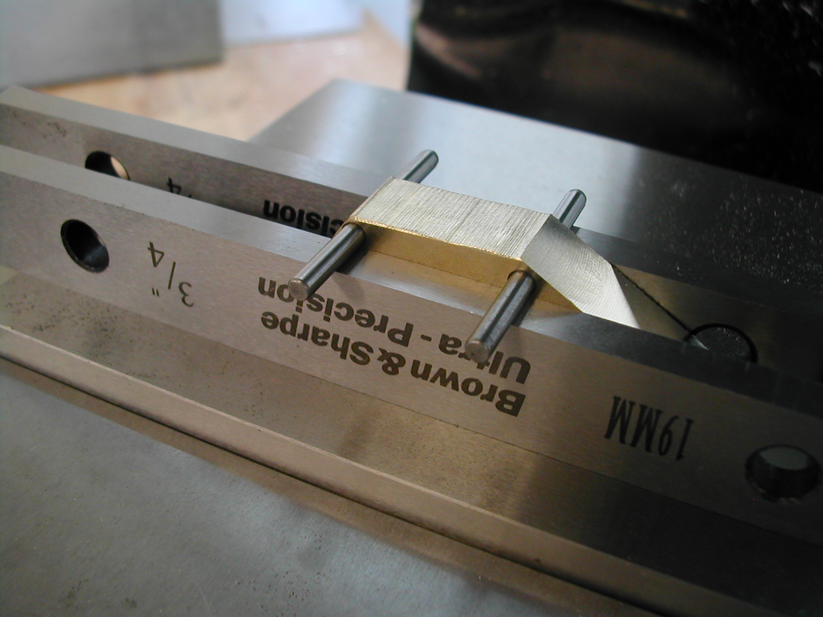 For our last two surfaces, insert the pins in the holes marked “C” & “D”. For these surfaces, you’ll need to raise the housing up on parallels and remove the parallels and pins once the housing is clamped in place.
 With the parallels and pins removed, proceed to mill surface #4 0.005″ below where holes “C” & “D” clean up. Repeat these last two steps for the other side.
 At this point, the housing is ready to be mounted in the Crankcase for match drilling the suction and pressure ports.
TO DO
- Mount in crankcase and machine transfer pipe holes.
- Tap suction and pressure ports.
Disclaimer and License
All material, including the CAD drawings, relating to the construction of the Hodgson Radial presented on this site is free to use any way you see fit. However, no guarantees are made regarding the accuracy or correctness of the material presented here.
Links Used On This Page
(CAD drawings are in AutoCAD 2010 Format)